EP0092527A2 - Device for humidifying air in space heating apparatus - Google Patents
Device for humidifying air in space heating apparatus Download PDFInfo
- Publication number
- EP0092527A2 EP0092527A2 EP83830051A EP83830051A EP0092527A2 EP 0092527 A2 EP0092527 A2 EP 0092527A2 EP 83830051 A EP83830051 A EP 83830051A EP 83830051 A EP83830051 A EP 83830051A EP 0092527 A2 EP0092527 A2 EP 0092527A2
- Authority
- EP
- European Patent Office
- Prior art keywords
- container
- hot air
- fact
- water
- panels
- Prior art date
- Legal status (The legal status is an assumption and is not a legal conclusion. Google has not performed a legal analysis and makes no representation as to the accuracy of the status listed.)
- Granted
Links
Images
Classifications
-
- F—MECHANICAL ENGINEERING; LIGHTING; HEATING; WEAPONS; BLASTING
- F24—HEATING; RANGES; VENTILATING
- F24D—DOMESTIC- OR SPACE-HEATING SYSTEMS, e.g. CENTRAL HEATING SYSTEMS; DOMESTIC HOT-WATER SUPPLY SYSTEMS; ELEMENTS OR COMPONENTS THEREFOR
- F24D19/00—Details
- F24D19/008—Details related to central heating radiators
- F24D19/0082—Humidifiers for radiators
-
- F—MECHANICAL ENGINEERING; LIGHTING; HEATING; WEAPONS; BLASTING
- F24—HEATING; RANGES; VENTILATING
- F24F—AIR-CONDITIONING; AIR-HUMIDIFICATION; VENTILATION; USE OF AIR CURRENTS FOR SCREENING
- F24F6/00—Air-humidification, e.g. cooling by humidification
- F24F6/02—Air-humidification, e.g. cooling by humidification by evaporation of water in the air
- F24F6/08—Air-humidification, e.g. cooling by humidification by evaporation of water in the air using heated wet elements
Definitions
- the invention relates to a device for humidifying the air in plants for heating the environment which can, in particular, be advantageously used in plants wherein the heating elements are constituted by convectors or unit heaters.
- a method frequently adopted to overcome the problem described consists in periodically opening the windows in the said area in order to recreate comfortable ambient conditions.
- the said solution is obviously not trouble free and is one that causes an increase in the running costs.
- Ambient humidifiers for heating plants that have electrical resistances for causing the water contained in special vessels to evaporate, are also known.
- the said devices give rise to a consumption of electricity that is not inconsiderable and, in addition, are somewhat costly because of their complexity.
- the object of the invention is, therefore, to make available an ordinary non-costly device for humidifying the air that is able to be fitted easily to any convector or unit heater, or to be incorporated therein at the time the convector or unit heater is being manufactured.
- a further object of the invention is to make available a device of the aforementioned type in which it is particularly easy both to check the amount of humidification water present and to top it up.
- the device according to the invention for humidifying the air in plants for heating the environment that comprise groups that deliver hot air, each of which incorporating the said device in a position located, with reference to the path followed by the heated air prior to its being admitted into the environment, downstream of a corresponding heating element;
- the said device comprising at least one container connected to a water intake element accessible from the outside of the group, and at least one tubular element that crosses the said container at least partially, placed in peripheral contact with the water present therein, through the inside of which hot air coming from the said heating element is able to pass; at least part of the inner surfaces of the said container being faced, at least partially, with panels of porous absorbing material.
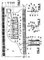
- Figure 1 is shown globally at 1 a convector, hereinafter also referred to as a group for the delivery of hot air, delimited at the front by a covering wall or front panel 2, and at the rear by a back panel 3.
- a convector hereinafter also referred to as a group for the delivery of hot air, delimited at the front by a covering wall or front panel 2, and at the rear by a back panel 3.
- a base wall 4 in the convector 1 supports, in a way not shown, a horizontal heating element 5, through which passes internally hot water taken thereto and there from via pipes 6 and 7, respectively, the former shown on the left and the latter on the right in Figure 1, terminating at a non illustrated boiler.
- the actual heat exchanging surface of the heating element 5 is constituted by a plurality of vertical metal strips 8, placed side by side perpendicularly to the panels 2 and 3.
- the said device 11 comprises a container 12 that extends parallel to the base wall 4 with the flat part thereof perpendicular to the panels 2 and 3, and this is open at the top and is defined on the four sides by two lateral walls 13 perpendicular to the panels 2 and 3, and by two walls 14 and 15 parallel to the latter and each facing one of the said two panels 2 and 3.
- the container 12 In a base wall shown at 16, the container 12 is provided with three circular apertures 17 spread uniformly there over. Above each aperture 17, as can also be seen in Figure 2, is placed a vertical tubular element 18 of truncated cone shape. The periphery of the widest end of this mates with the edge of the corresponding aperture 17, to which it is imperviously connected. The upper extremity of each of the tubular elements 18 is located beneath the apex of the container 12, and is topped by a concave cover or deviation element 19 that is supported in a way not shown, with the concavity pointing downwards. The dimensions of the cover 19 are such as to leave, between it and the lateral walls 13, 14 and 15 of the container 12, a virtually annular passage shown at 20.
- Two panels 21 of felt, sponge or some other porous absorbing material are firmly attached to the inner surfaces of the container 12 on the walls 14 and 15, over the full transverse extension thereof, stretching from the base of the latter up to a level higher than that of the cover 19.
- the righthand upper part of the panel 2 is provided with a virtually square opening 22, to one of the lower horizontal sides of which is pivoted, in a way not shown, a lower corner edge 23 of a water intake element 24, comprising a box 25 whose shape is virtually prismatic (see in this connection Figures 3 and 4).
- the said box 25 is delimited on two sides by two triangular walls 26 and 27 perpendicular to the panel 2, the sides of which converging towards the said corner edge 23 are jointed by the wall 28 (shown on the left in Figure 3) and by the wall 29 (shown on the right in Figure 4).
- the wall 28 In proximity of the corner edge 23, the wall 28 is provided with a non-illustrated hole, to which is connected one extremity of a tube 30 whose other extremity is connected to the container 12.
- a level indicator 31 constituted by a vertical cylindrical container 32 that is closed at the bottom and is made of transparent material, is connected, low down, to the bottom part of the container 12 via a connecting pipe 33, and is housed inside the convector 1 in the region of a vertical display slit that is not shown but is made in the panel 2.
- the surface of the cylindrical container 32 is provided with a non-illustrated graduated scale, and internally with a float 34 designed to indicate on the said graduated scale the amount of water present in the container 12.
- the intake of water into the container 12 is effected through the box 25, once it has been made to rotate around the corner edge 23 in order to carry it from the position shown in Figure 3 to that shown in Figure 4.
- part of the air heated by the heating clement 5 passes, while moving upwards towards the apertures 9, inside the tubular elements 13 and is deviated by the cover 19 towards the surface of the water present in the container 12 and towards the panels 21 which, due to capillarity phenomena, are damp even in the areas over which the water does not glide.
- the hot air, thus humidified then reaches the environment, passing through the apertures 9.
- the container 12 in order to increase the evaporation surface of the panels 21, can be of any shape, or be substituted by a number of smaller containers, side by side and interconnected, all having the inner lateral walls faced with absorbing material.
- the number and the shape of the tubular elements 18 can differ from what has been stated by way of an example, and the said porous absorbing material facing can be placed, additionally or alternatively to that provided on the inner surface of the container 12, on the periphery of the said tubular elements 18.
Landscapes
- Engineering & Computer Science (AREA)
- General Engineering & Computer Science (AREA)
- Chemical & Material Sciences (AREA)
- Combustion & Propulsion (AREA)
- Mechanical Engineering (AREA)
- Thermal Sciences (AREA)
- Physics & Mathematics (AREA)
- Air Humidification (AREA)
- Air Conditioning Control Device (AREA)
- Fuel Cell (AREA)
- Cultivation Receptacles Or Flower-Pots, Or Pots For Seedlings (AREA)
- Fertilizers (AREA)
- Cold Air Circulating Systems And Constructional Details In Refrigerators (AREA)
Abstract
Description
- The invention relates to a device for humidifying the air in plants for heating the environment which can, in particular, be advantageously used in plants wherein the heating elements are constituted by convectors or unit heaters.
- As is known, provision is not generally made by the manufacturers, in plants of the said type, for any device able to cause the humidification of the heated air which, not infrequently, is of a relative humidity such as to give the persons present in the area heated, excessive dryness in their respiratory organs.
- A method frequently adopted to overcome the problem described consists in periodically opening the windows in the said area in order to recreate comfortable ambient conditions. The said solution is obviously not trouble free and is one that causes an increase in the running costs.
- Another method that is used quite extensively is to place on the heating element, inside the metal box shaped body by which it is covered, a container filled with water. This type of solution is not devoid of problems since the said container smothers the circulation of the air between the upper part of the heating element and the apertures through which the hot air is admitted into the environment, thereby decreasing the output of the plant. Furthermore, the checking of the amount of water present and the topping up of this necessitates removing one of the panels that encloses the convector, that is to say, performing operations that are none too easy since they are not foreseen as being customary by manufacturers of heating plants of this type.
- Ambient humidifiers for heating plants that have electrical resistances for causing the water contained in special vessels to evaporate, are also known. The said devices give rise to a consumption of electricity that is not inconsiderable and, in addition, are somewhat costly because of their complexity.
- The object of the invention is, therefore, to make available an ordinary non-costly device for humidifying the air that is able to be fitted easily to any convector or unit heater, or to be incorporated therein at the time the convector or unit heater is being manufactured.
- A further object of the invention is to make available a device of the aforementioned type in which it is particularly easy both to check the amount of humidification water present and to top it up.
- These and other objects too are all attained by the device according to the invention for humidifying the air in plants for heating the environment that comprise groups that deliver hot air, each of which incorporating the said device in a position located, with reference to the path followed by the heated air prior to its being admitted into the environment, downstream of a corresponding heating element; the said device comprising at least one container connected to a water intake element accessible from the outside of the group, and at least one tubular element that crosses the said container at least partially, placed in peripheral contact with the water present therein, through the inside of which hot air coming from the said heating element is able to pass; at least part of the inner surfaces of the said container being faced, at least partially, with panels of porous absorbing material.
- Further characteristics and advantages of the invention will become more apparent from the description that follows of one preferred embodiment, given purely as an unlimited example on the accompanying drawings, in which :
- - Figure 1 shows, diagrammatically and partially in sectional form, a convector provided with the device according to the invention for humidifying the air;
- - Figure 2 shows, in a sectional view along a plane 11-11, the device depicted in Figure 1;
- - Figures 3 and 4 show, in a lateral diagrammatic view partially in sectional form, one detail in Figure 1 depicted in two different operating conditions.
- In Figure 1 is shown globally at 1 a convector, hereinafter also referred to as a group for the delivery of hot air, delimited at the front by a covering wall or
front panel 2, and at the rear by aback panel 3. - A base wall 4 in the convector 1 supports, in a way not shown, a
horizontal heating element 5, through which passes internally hot water taken thereto and there from via pipes 6 and 7, respectively, the former shown on the left and the latter on the right in Figure 1, terminating at a non illustrated boiler. - The actual heat exchanging surface of the
heating element 5 is constituted by a plurality of vertical metal strips 8, placed side by side perpendicularly to thepanels - A plurality of apertures 9, one at the side of the other and virtually rectangular, delimited by
grids 10 and spread at regular intervals over the full width of the said panel 2, are provided in the region of the upper part of thepanel 2. Above theheating element 5 is provided ahumidifier device 11, supported in a way that is not shown by thepanel 3. - The
said device 11 comprises acontainer 12 that extends parallel to the base wall 4 with the flat part thereof perpendicular to thepanels lateral walls 13 perpendicular to thepanels walls panels - In a base wall shown at 16, the
container 12 is provided with threecircular apertures 17 spread uniformly there over. Above eachaperture 17, as can also be seen in Figure 2, is placed a verticaltubular element 18 of truncated cone shape. The periphery of the widest end of this mates with the edge of thecorresponding aperture 17, to which it is imperviously connected. The upper extremity of each of thetubular elements 18 is located beneath the apex of thecontainer 12, and is topped by a concave cover ordeviation element 19 that is supported in a way not shown, with the concavity pointing downwards. The dimensions of thecover 19 are such as to leave, between it and thelateral walls container 12, a virtually annular passage shown at 20. - Two
panels 21 of felt, sponge or some other porous absorbing material are firmly attached to the inner surfaces of thecontainer 12 on thewalls cover 19. - The righthand upper part of the
panel 2 is provided with a virtuallysquare opening 22, to one of the lower horizontal sides of which is pivoted, in a way not shown, alower corner edge 23 of awater intake element 24, comprising abox 25 whose shape is virtually prismatic (see in this connection Figures 3 and 4). The saidbox 25 is delimited on two sides by twotriangular walls panel 2, the sides of which converging towards thesaid corner edge 23 are jointed by the wall 28 (shown on the left in Figure 3) and by the wall 29 (shown on the right in Figure 4). In proximity of thecorner edge 23, thewall 28 is provided with a non-illustrated hole, to which is connected one extremity of atube 30 whose other extremity is connected to thecontainer 12. - A
level indicator 31, constituted by a verticalcylindrical container 32 that is closed at the bottom and is made of transparent material, is connected, low down, to the bottom part of thecontainer 12 via a connectingpipe 33, and is housed inside the convector 1 in the region of a vertical display slit that is not shown but is made in thepanel 2. The surface of thecylindrical container 32 is provided with a non-illustrated graduated scale, and internally with afloat 34 designed to indicate on the said graduated scale the amount of water present in thecontainer 12. - In use, the intake of water into the
container 12 is effected through thebox 25, once it has been made to rotate around thecorner edge 23 in order to carry it from the position shown in Figure 3 to that shown in Figure 4. During the operation of the convector 1, part of the air heated by theheating clement 5 passes, while moving upwards towards the apertures 9, inside thetubular elements 13 and is deviated by thecover 19 towards the surface of the water present in thecontainer 12 and towards thepanels 21 which, due to capillarity phenomena, are damp even in the areas over which the water does not glide. The hot air, thus humidified, then reaches the environment, passing through the apertures 9. - Naturally, leaving unchanged the principles of the invention, numerous are the modifications it would be possible to make to the device as described without in any way deviating from the framework of protection afforded to the invention.
- For example, in order to increase the evaporation surface of the
panels 21, thecontainer 12 can be of any shape, or be substituted by a number of smaller containers, side by side and interconnected, all having the inner lateral walls faced with absorbing material. Furthermore, the number and the shape of thetubular elements 18 can differ from what has been stated by way of an example, and the said porous absorbing material facing can be placed, additionally or alternatively to that provided on the inner surface of thecontainer 12, on the periphery of the saidtubular elements 18.
Claims (5)
Priority Applications (1)
| Application Number | Priority Date | Filing Date | Title |
|---|---|---|---|
| AT83830051T ATE14921T1 (en) | 1982-04-16 | 1983-03-09 | DEVICE FOR AIR HUMIDIFICATION IN ROOM HEATING PLANTS. |
Applications Claiming Priority (2)
| Application Number | Priority Date | Filing Date | Title |
|---|---|---|---|
| IT03401/82A IT1192891B (en) | 1982-04-16 | 1982-04-16 | AIR HUMIDIFIER IN THE SYSTEM FOR ENVIRONMENTAL HEATING |
| IT340182 | 1982-04-16 |
Publications (3)
| Publication Number | Publication Date |
|---|---|
| EP0092527A2 true EP0092527A2 (en) | 1983-10-26 |
| EP0092527A3 EP0092527A3 (en) | 1984-01-04 |
| EP0092527B1 EP0092527B1 (en) | 1985-08-14 |
Family
ID=11106428
Family Applications (1)
| Application Number | Title | Priority Date | Filing Date |
|---|---|---|---|
| EP83830051A Expired EP0092527B1 (en) | 1982-04-16 | 1983-03-09 | Device for humidifying air in space heating apparatus |
Country Status (4)
| Country | Link |
|---|---|
| EP (1) | EP0092527B1 (en) |
| AT (1) | ATE14921T1 (en) |
| DE (1) | DE3360547D1 (en) |
| IT (1) | IT1192891B (en) |
Cited By (6)
| Publication number | Priority date | Publication date | Assignee | Title |
|---|---|---|---|---|
| GB2177933A (en) * | 1985-04-22 | 1987-02-04 | James Anthony Maguire | Furnace register humidifier |
| EP1519118A1 (en) * | 2003-09-18 | 2005-03-30 | Martin Dr.-Ing. Möritz | Method and device for air humidification of rooms and vehicles |
| WO2006103108A1 (en) * | 2005-03-29 | 2006-10-05 | Martin Moertiz | Device and method for humidifying an air flow |
| FR3007111A1 (en) * | 2013-06-13 | 2014-12-19 | Kouri Zaidan El | LIQUID HEATING RADIATOR WITH VENTILATION TURBINE, HUMIDIFICATION SYSTEM AND PARFUMMER SYSTEM |
| DE102015224564A1 (en) | 2015-12-08 | 2017-06-08 | Deere & Company | Mowing and intake device for a machine for mowing stalk-like crops |
| WO2023246064A1 (en) * | 2022-06-24 | 2023-12-28 | 珠海格力电器股份有限公司 | Humidifying electric heater |
Family Cites Families (6)
| Publication number | Priority date | Publication date | Assignee | Title |
|---|---|---|---|---|
| DE7208488U (en) * | 1972-06-08 | Vama Vertrieb Gmbh & Co Kg | Air humidifier for radiators | |
| DE7216479U (en) * | 1972-10-19 | Wibo-Werk Hamburg W Bottermann | Baseboard heating | |
| GB521168A (en) * | 1938-11-10 | 1940-05-14 | Electro Horticultural Equipmen | Improvements in or relating to electric convection heaters for greenhouses and the like |
| DE1719542U (en) * | 1956-01-09 | 1956-03-29 | Kurt Wagner | HUMIDIFIER IN CONNECTION WITH CONVECTOR HEATING ELEMENTS. |
| DE1925080A1 (en) * | 1969-05-16 | 1970-11-19 | Georg Boettinger | Radiator cladding and room air humidification device |
| FR2265046A1 (en) * | 1974-03-18 | 1975-10-17 | Guerineau Ste Alsac Electricit | Electrically operated convective room heater - has integral air humidifier within casing with deflector guiding air over it |
-
1982
- 1982-04-16 IT IT03401/82A patent/IT1192891B/en active
-
1983
- 1983-03-09 EP EP83830051A patent/EP0092527B1/en not_active Expired
- 1983-03-09 DE DE8383830051T patent/DE3360547D1/en not_active Expired
- 1983-03-09 AT AT83830051T patent/ATE14921T1/en not_active IP Right Cessation
Cited By (8)
| Publication number | Priority date | Publication date | Assignee | Title |
|---|---|---|---|---|
| GB2177933A (en) * | 1985-04-22 | 1987-02-04 | James Anthony Maguire | Furnace register humidifier |
| EP1519118A1 (en) * | 2003-09-18 | 2005-03-30 | Martin Dr.-Ing. Möritz | Method and device for air humidification of rooms and vehicles |
| WO2006103108A1 (en) * | 2005-03-29 | 2006-10-05 | Martin Moertiz | Device and method for humidifying an air flow |
| EP1710516A1 (en) * | 2005-03-29 | 2006-10-11 | Martin Dr.-Ing. Möritz | Device and method for humidifying an airflow |
| FR3007111A1 (en) * | 2013-06-13 | 2014-12-19 | Kouri Zaidan El | LIQUID HEATING RADIATOR WITH VENTILATION TURBINE, HUMIDIFICATION SYSTEM AND PARFUMMER SYSTEM |
| DE102015224564A1 (en) | 2015-12-08 | 2017-06-08 | Deere & Company | Mowing and intake device for a machine for mowing stalk-like crops |
| EP3178308A1 (en) | 2015-12-08 | 2017-06-14 | Deere & Company | Mowing and collection device for a machine for mowing stalk-like crops |
| WO2023246064A1 (en) * | 2022-06-24 | 2023-12-28 | 珠海格力电器股份有限公司 | Humidifying electric heater |
Also Published As
| Publication number | Publication date |
|---|---|
| DE3360547D1 (en) | 1985-09-19 |
| EP0092527A3 (en) | 1984-01-04 |
| EP0092527B1 (en) | 1985-08-14 |
| IT1192891B (en) | 1988-05-26 |
| IT8203401A0 (en) | 1982-04-16 |
| ATE14921T1 (en) | 1985-08-15 |
Similar Documents
| Publication | Publication Date | Title |
|---|---|---|
| US5010845A (en) | Reptile cage apparatus | |
| US4970876A (en) | Evaporative cooler | |
| US3187744A (en) | Incubator | |
| EP0092527A2 (en) | Device for humidifying air in space heating apparatus | |
| US2709838A (en) | Greenhouse | |
| US3355155A (en) | Humidifier for air conditioning systems | |
| CN112747401A (en) | Humidification subassembly and electric heater | |
| US7828275B2 (en) | Humidifier for use with heated air source | |
| CN107906606A (en) | Air conditioner humidification system | |
| CN214370682U (en) | Humidification subassembly and electric heater | |
| EP3961116B1 (en) | Air humidifier | |
| US1961711A (en) | Humidifier and sterilizer | |
| JPH07107457B2 (en) | Humidifier for air conditioner | |
| US3623547A (en) | Combination heater and humidifier | |
| US1839357A (en) | Combination warm air cleaner and heat deflector | |
| US3409219A (en) | Humidifier | |
| US2091957A (en) | Humidifier | |
| JP3100288B2 (en) | humidifier | |
| CN218680308U (en) | Vegetation evaporation analogue means | |
| US1760633A (en) | Humidifier | |
| US1725005A (en) | Humidifier | |
| US1892686A (en) | Humidifier | |
| JPS5843716Y2 (en) | Warm air vaporization humidifier | |
| SU1103834A1 (en) | Incubator | |
| US1857770A (en) | Humidifier |
Legal Events
| Date | Code | Title | Description |
|---|---|---|---|
| PUAI | Public reference made under article 153(3) epc to a published international application that has entered the european phase |
Free format text: ORIGINAL CODE: 0009012 |
|
| AK | Designated contracting states |
Designated state(s): AT BE CH DE FR GB LI LU NL SE |
|
| PUAL | Search report despatched |
Free format text: ORIGINAL CODE: 0009013 |
|
| AK | Designated contracting states |
Designated state(s): AT BE CH DE FR GB LI LU NL SE |
|
| 17P | Request for examination filed |
Effective date: 19840203 |
|
| GRAA | (expected) grant |
Free format text: ORIGINAL CODE: 0009210 |
|
| AK | Designated contracting states |
Designated state(s): AT BE CH DE FR GB LI LU NL SE |
|
| PG25 | Lapsed in a contracting state [announced via postgrant information from national office to epo] |
Ref country code: NL Effective date: 19850814 Ref country code: BE Effective date: 19850814 Ref country code: AT Effective date: 19850814 |
|
| REF | Corresponds to: |
Ref document number: 14921 Country of ref document: AT Date of ref document: 19850815 Kind code of ref document: T |
|
| PG25 | Lapsed in a contracting state [announced via postgrant information from national office to epo] |
Ref country code: SE Effective date: 19850830 |
|
| REF | Corresponds to: |
Ref document number: 3360547 Country of ref document: DE Date of ref document: 19850919 |
|
| ET | Fr: translation filed | ||
| NLV1 | Nl: lapsed or annulled due to failure to fulfill the requirements of art. 29p and 29m of the patents act | ||
| PG25 | Lapsed in a contracting state [announced via postgrant information from national office to epo] |
Ref country code: LU Free format text: LAPSE BECAUSE OF NON-PAYMENT OF DUE FEES Effective date: 19860331 |
|
| PLBE | No opposition filed within time limit |
Free format text: ORIGINAL CODE: 0009261 |
|
| STAA | Information on the status of an ep patent application or granted ep patent |
Free format text: STATUS: NO OPPOSITION FILED WITHIN TIME LIMIT |
|
| 26N | No opposition filed | ||
| GBPC | Gb: european patent ceased through non-payment of renewal fee | ||
| PG25 | Lapsed in a contracting state [announced via postgrant information from national office to epo] |
Ref country code: GB Effective date: 19881122 |
|
| PG25 | Lapsed in a contracting state [announced via postgrant information from national office to epo] |
Ref country code: LI Effective date: 19890331 Ref country code: CH Effective date: 19890331 |
|
| PG25 | Lapsed in a contracting state [announced via postgrant information from national office to epo] |
Ref country code: FR Free format text: LAPSE BECAUSE OF NON-PAYMENT OF DUE FEES Effective date: 19891130 |
|
| REG | Reference to a national code |
Ref country code: CH Ref legal event code: PL |
|
| PG25 | Lapsed in a contracting state [announced via postgrant information from national office to epo] |
Ref country code: DE Effective date: 19891201 |
|
| REG | Reference to a national code |
Ref country code: FR Ref legal event code: ST |