EP0092501A2 - Helikoptermotorsteuerung zum Brennstoffsparen im stationären Flug - Google Patents
Helikoptermotorsteuerung zum Brennstoffsparen im stationären Flug Download PDFInfo
- Publication number
- EP0092501A2 EP0092501A2 EP83630062A EP83630062A EP0092501A2 EP 0092501 A2 EP0092501 A2 EP 0092501A2 EP 83630062 A EP83630062 A EP 83630062A EP 83630062 A EP83630062 A EP 83630062A EP 0092501 A2 EP0092501 A2 EP 0092501A2
- Authority
- EP
- European Patent Office
- Prior art keywords
- signal
- speed
- fuel
- providing
- indicative
- Prior art date
- Legal status (The legal status is an assumption and is not a legal conclusion. Google has not performed a legal analysis and makes no representation as to the accuracy of the status listed.)
- Granted
Links
- 239000000446 fuel Substances 0.000 title claims abstract description 155
- 230000004044 response Effects 0.000 claims abstract description 15
- 238000005070 sampling Methods 0.000 claims description 20
- 238000012545 processing Methods 0.000 claims description 15
- 230000008859 change Effects 0.000 claims description 11
- 230000001965 increasing effect Effects 0.000 claims description 6
- 230000007423 decrease Effects 0.000 claims description 5
- 230000000694 effects Effects 0.000 claims description 4
- 238000012360 testing method Methods 0.000 description 83
- 239000007789 gas Substances 0.000 description 14
- RZVHIXYEVGDQDX-UHFFFAOYSA-N 9,10-anthraquinone Chemical compound C1=CC=C2C(=O)C3=CC=CC=C3C(=O)C2=C1 RZVHIXYEVGDQDX-UHFFFAOYSA-N 0.000 description 9
- 238000010586 diagram Methods 0.000 description 7
- 125000004122 cyclic group Chemical group 0.000 description 4
- 230000000977 initiatory effect Effects 0.000 description 3
- 230000003094 perturbing effect Effects 0.000 description 3
- 238000009825 accumulation Methods 0.000 description 2
- 238000000034 method Methods 0.000 description 2
- 238000012935 Averaging Methods 0.000 description 1
- 230000004308 accommodation Effects 0.000 description 1
- 230000003044 adaptive effect Effects 0.000 description 1
- 238000007792 addition Methods 0.000 description 1
- 230000003466 anti-cipated effect Effects 0.000 description 1
- 238000006243 chemical reaction Methods 0.000 description 1
- 238000004590 computer program Methods 0.000 description 1
- 230000001419 dependent effect Effects 0.000 description 1
- 230000002542 deteriorative effect Effects 0.000 description 1
- 230000010006 flight Effects 0.000 description 1
- 230000001939 inductive effect Effects 0.000 description 1
- 238000013101 initial test Methods 0.000 description 1
- 238000004519 manufacturing process Methods 0.000 description 1
- 239000011159 matrix material Substances 0.000 description 1
- 238000005457 optimization Methods 0.000 description 1
- 230000000149 penetrating effect Effects 0.000 description 1
- 230000008569 process Effects 0.000 description 1
- 230000035945 sensitivity Effects 0.000 description 1
- 238000004088 simulation Methods 0.000 description 1
- 238000012546 transfer Methods 0.000 description 1
Images


Classifications
-
- F—MECHANICAL ENGINEERING; LIGHTING; HEATING; WEAPONS; BLASTING
- F02—COMBUSTION ENGINES; HOT-GAS OR COMBUSTION-PRODUCT ENGINE PLANTS
- F02C—GAS-TURBINE PLANTS; AIR INTAKES FOR JET-PROPULSION PLANTS; CONTROLLING FUEL SUPPLY IN AIR-BREATHING JET-PROPULSION PLANTS
- F02C9/00—Controlling gas-turbine plants; Controlling fuel supply in air- breathing jet-propulsion plants
- F02C9/26—Control of fuel supply
- F02C9/28—Regulating systems responsive to plant or ambient parameters, e.g. temperature, pressure, rotor speed
-
- G—PHYSICS
- G05—CONTROLLING; REGULATING
- G05D—SYSTEMS FOR CONTROLLING OR REGULATING NON-ELECTRIC VARIABLES
- G05D1/00—Control of position, course, altitude or attitude of land, water, air or space vehicles, e.g. using automatic pilots
- G05D1/0005—Control of position, course, altitude or attitude of land, water, air or space vehicles, e.g. using automatic pilots with arrangements to save energy
-
- G—PHYSICS
- G05—CONTROLLING; REGULATING
- G05D—SYSTEMS FOR CONTROLLING OR REGULATING NON-ELECTRIC VARIABLES
- G05D1/00—Control of position, course, altitude or attitude of land, water, air or space vehicles, e.g. using automatic pilots
- G05D1/08—Control of attitude, i.e. control of roll, pitch, or yaw
- G05D1/0808—Control of attitude, i.e. control of roll, pitch, or yaw specially adapted for aircraft
- G05D1/0858—Control of attitude, i.e. control of roll, pitch, or yaw specially adapted for aircraft specially adapted for vertical take-off of aircraft
-
- F—MECHANICAL ENGINEERING; LIGHTING; HEATING; WEAPONS; BLASTING
- F05—INDEXING SCHEMES RELATING TO ENGINES OR PUMPS IN VARIOUS SUBCLASSES OF CLASSES F01-F04
- F05D—INDEXING SCHEME FOR ASPECTS RELATING TO NON-POSITIVE-DISPLACEMENT MACHINES OR ENGINES, GAS-TURBINES OR JET-PROPULSION PLANTS
- F05D2220/00—Application
- F05D2220/30—Application in turbines
- F05D2220/32—Application in turbines in gas turbines
- F05D2220/329—Application in turbines in gas turbines in helicopters
-
- F—MECHANICAL ENGINEERING; LIGHTING; HEATING; WEAPONS; BLASTING
- F05—INDEXING SCHEMES RELATING TO ENGINES OR PUMPS IN VARIOUS SUBCLASSES OF CLASSES F01-F04
- F05D—INDEXING SCHEME FOR ASPECTS RELATING TO NON-POSITIVE-DISPLACEMENT MACHINES OR ENGINES, GAS-TURBINES OR JET-PROPULSION PLANTS
- F05D2270/00—Control
- F05D2270/01—Purpose of the control system
- F05D2270/07—Purpose of the control system to improve fuel economy
-
- Y—GENERAL TAGGING OF NEW TECHNOLOGICAL DEVELOPMENTS; GENERAL TAGGING OF CROSS-SECTIONAL TECHNOLOGIES SPANNING OVER SEVERAL SECTIONS OF THE IPC; TECHNICAL SUBJECTS COVERED BY FORMER USPC CROSS-REFERENCE ART COLLECTIONS [XRACs] AND DIGESTS
- Y02—TECHNOLOGIES OR APPLICATIONS FOR MITIGATION OR ADAPTATION AGAINST CLIMATE CHANGE
- Y02T—CLIMATE CHANGE MITIGATION TECHNOLOGIES RELATED TO TRANSPORTATION
- Y02T50/00—Aeronautics or air transport
- Y02T50/60—Efficient propulsion technologies, e.g. for aircraft
Definitions
- This invention relates to helicopter engine controls, and more particularly to a helicopter engine control which provides for minimum fuel consumption during cruise mode.
- the flight performance of a helicopter is very highly dependent among other things upon the speed and torque provided to the main rotor, and thus the thrust provided by the main rotor.
- the helicopter rotor is driven at some fixed rated speed, and variations in the thrust imparted thereby and therefore torque imparted thereto are caused by variations in the rotor blade pitch angles, including collective pitch for speed and lift and cyclic pitch variations for longitudinal and lateral attitude control.
- the fuel control for a typical helicopter free turbine gas engine modulates fuel to the engine in a fashion to maintain the free turbine speed equal to rated rotor speed, except to the extent that the pilot may nudge the free turbine speed set point (NF SET) upward or downward a small amount with a beeper.
- NF SET free turbine speed set point
- the torque requirements vary with aircraft weight and speed, which establish such factors as induced drag coefficients which correspond with the high angle of attack required for lower rotor speeds, which must be traded off against increase in drag coefficient which results from the advancing blades penetrating deeply beyond the critical Mach number at higher rotor speeds.
- the minimum power (and therefore fuel) operating point is a trade-off between blade angle of attack and rotor RPM.
- the rotor blades are capable of operating at lower angles of attack per rotor speed.
- drag coefficients are low and the sensitivity of rotor RPM on power requirements is less than it is when the aircraft is heavily loaded, flying at higher speed, or the air density is less (higher temperature and/or higher altitude).
- Objects of the invention include provision of a helicopter engine control which utilizes minimum fuel when the helicopter is operating in a cruise mode.
- a helicopter engine control provides an optimum rotor speed setting as the reference speed of the rotor driving free turbine which is utilized to determine the amount of fuel to be metered to the engine.
- the optimum speed is detennined by an adaptive control which perturbs the reference speed setting by a small increment and compares the fuel flow rate required to maintain the perturbed setting with a fuel flow rate determi ned prior to perturbing the turbine reference speed; the fuel flow rate is determined by averaging a very large sample of values of fuel commanded to the fuel metering valve.
- a desired miminum fuel reference speed is established by means of a schedule which is determined in accordance with aircraft total weight, outside air temperature, altitude and airspeed.
- transfer between controlling the engine with respect to a normal (rated) reference speed or an estimated optimal reference speed accomplished by fade-in and fade-out routines to avoid perturbing the operation of the engine by any significant amount.
- the present invention is easily implemented in a digital fuel control by means of relatively simple program steps; the invention may also be implemented by means of discrete hardware, if desired, utilizing only apparatus and techniques which are readily available and well known in the art, in the light of the teachings which follow hereinafter.
- the invention provides on the order of 10% fuel savings in helicopters operating in a cruise mode without deteriorating the performance required during maneuvers.
- Fuel flow requirements are established for any given helicopter in various operating conditions by integrating combing) the power required by the main rotor, tail rotor and accessories at any given rotor drive speed, with engine characteristics at the corresponding rotor drive speed and the same power for the same operating conditions.
- Such data can be derived from analytical models or from actual test results. Analytically, sophisticated mathematical simulation models of the helicopter system, such as those represented in NASA TM 78629 or Sikorsky Aircraft Report SER 70452 may be used to derive the data. Alternatively, the necessary data can be imperically determined from flight testing a given aircraft. The aircraft can be flight tested throughout the flight envelope and fuel flow is actually measured to establish a fuel requiments data bank.
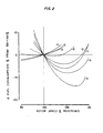
- Fig. 2 illustrates that fuel savings (for the given aircraft represented in Fig. 2) may be as great as 12% (compared to the fuel required at rated speed) for a heavy helicopter flying at high speed and altitude over the desert, as shown by curve A.
- fuel savings for the given aircraft represented in Fig. 2
- the fuel consumption is essentially minimal at or near rated speed, so little savings can be effected as indicated by curve E in Fig. 2.
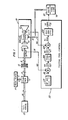
- a main rotor 10 is connected through a shaft 12 to a gear box 13 which is driven by a shaft 14 through an overrunning clutch 16, which engages an output shaft 18 of an engine 20 when the engine speed equals or exceeds the rotor speed.
- the gear box 13 also drives a tail rotor 22 through a shaft 24 so that the main rotor 10 and the tail rotor 22 are always driven at speeds bearing a fixed relationship to each other, such as the tail rotor rotating about five times faster than the main rotor.
- the engine 20 may typically comprise a free turbine gas engine in which the output shaft 18 is driven by a free turbine 40, which is in turn driven by gases fran a gas generator including a turbocompressor having a compressor 42 connected by a shaft 44 to a compressor-driving turbine 46, and a burner section 47 to which fuel is supplied by fuel lines 50 from a fuel control metering valve 52.
- a fuel control 53 typically tries to provide the correct rate of fuel (WF) in the fuel inlet lines 50 so as to maintain a desired engine speed (NF) as determined by a tachometer 54 which measures the speed of the free turbine 40 (such as on the output shaft 18) to provide a turbine speed indicating signal on a line 56 to a summing junction 60 (or equivalent function).
- the other inputs to the summing junction 60 comprise the reference speed (NF SET), which typically is a reference value indicative of 100% rated speed derived from a source 62 together with any pilot-desired variant therein as determined by a signal from the pilot's engine speed beeper.
- the output of the summing junction 60 is a speed error signal (NF ERR) on a line 65 which is applied to a turbine control (or governor) portion 66 of the fuel control, the output of which is a required gas generator speed signal (NG SET) on a line 67, which is fed to a summing junction 68 at the input of a gas generator control portion 69 of the fuel control.
- NF ERR speed error signal
- NG SET required gas generator speed signal
- the summing junction 68 is also responsive to a signal indicative of gas generator speed (NG) on a line 70 which may be taken from a tachometer 71 responsive to the gas generator spool including the canpressor 42, the shaft 44 and the turbine 46.
- the gas generator control 69 provides a commanded fuel rate (WF CMND) on a line 73 which is applied to the metering valve 52 so as to cause the correct amount of fuel from a fuel pump 74 to be supplied to the fuel inlet lines 50, as a function of the difference between the required and actual gas generator speed indications, in a well known fashion.
- WF CMND commanded fuel rate
- the engine reference speed may be provided in the usual fashion (100% reference plus or minus pilot beeping) or, faded into a cruise mode in which minimum fuel consumption is attained.
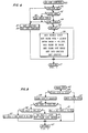
- the invention is described as it may be implemented in a digital fuel control, an NF SET program for which is described with respect to Fig. 3.
- the NF SET program is entered in Fig. 3 through an entry point 80.
- the weight of fuel which has been consumed is continuously monitored by calculating it in every computer cycle in a step 81, in which fuel consumed has added to it some constant times the currently sampled value of the fuel command (NF CMND).
- the constant (KW) is selected to take into account the cyclic period of the computer and the weight of fuel per command.
- the step 81 integrates the fuel commands to show the weight of fuel consumed.
- a cruise control subroutine illustrated in Fig. 4 is performed to determine if the cruise mode of the present invention should be initiated, or terminated if already in progress.
- the cruise control subroutine is reached through an entry point 83 and a first test 84 determines whether the pilot has activated a cruise mode switch or not. If not, a negative result of test 84 reaches a step 85 which resets a cruise indicating flag and a step 86 which resets a cruise mode indication to the pilot. And then the NF SET program of Fig. 3 is reached through a return point 87.
- a next test 88 determines if the cruise mode has been set or not.
- a test 89 determines if fade-out is required. In the general case, other than when the cruise mode has just been terminated, there will not be a fade-out request outstanding so that a negative result of test 89 will reach a subroutine which provides the engine reference speed in a normal fashion, as is illustrated in Fig. 5.
- a first test 92 determines if' the pilot has made a positive beep to increase the engine reference speed. If so, the engine reference value NF SET is incremented by a beeper increment in a step 93, but if not, a negative result of test 92 reaches a test 94 which determines if the pilot has requested a decrease in engine reference speed by means of his beeper. If so, the reference speed is decremented by the beeper increment in a step 95. If the pilot has required no beeping, the reference speed is left set as it was originally.
- a test 97 determines if the reference speed is greater than 110% of rated speed. If it is, a step 98 sets the referene speed to 110% of rated speed. But if not, a negative result of test 97 reaches a test 99 to determine if the reference speed is below 95% of rated speed. If it is, the reference speed is set equal to 95% of rated speed in a step 100. If not, NF SET is not altered. When the limiting (if any) has been accomplished, the NF SET routine of Fig. 3 is ended through an end of return point 101, and the computer reverts to performing other tasks.
- test 84 will be affirmative reaching a test 102 which determines whether the automatic flight control system of the aircraft is engaged or not. If not, a negative result of test 102 will reach a step 103 which causes an indicator to be lit to inform the pilot that he should engage his autopilot before he can enter the cruise mode (although, the invention could be used with the pilot controlling the helicopter trim manually). In that case, redundant resetting of the cruise and indicator cruise flags in steps 85 and 86 are accomplished and the NF SET program of Fig. 3 is reverted to at test 88 and normal reference speed setting will be accomplished through the subroutine of Fig. 5 as described hereinbefore.
- a test 104 determines whether the pilot is applying stick force against the trim established by the automatic flight control system. If he is, the resulting maneuvers render it impossible to maintain a desired cruise minimum fuel flow rate, so that the cruise mode (if it had been engaged) will become disengaged by an affirmative result of test 104 reaching the steps 85 and 86 as described hereinbefore.
- passage through the subroutine of Fig. 4 will be in response to a negative result of the test 104 which reaches a test 105 to determine if the cruise mode flag has been set or not.
- a series of steps 106 provide initialization for the cruise mode by resetting a schedule initiated flag (utilized in the fade-in subroutine of Fig. 6), resetting a fade counter (utilized in the fade-in subroutine of Fig. 6 and in the fade-out subroutine of Fig. 8), resetting a fade-in done flag and setting a fade-out required flag (both utilized in the NF SET program of Fig. 3), and setting the cruise flag (a pilot indication that the cruise mode has been entered). Then the NF SET program of Fig. 3 is returned to through the return point 87.
- the cruise control subroutine of Fig. 4 is passed through in each machine cycle to determine if cruise should be entered or terminated, so as to determine the correct mode of setting the turbine reference speed.
- test 88 will be affirmative reaching a test 107 which determines if fade-in is done or not. Initially, fade-in is not done as indicated by the flag set in step 106 in Fig. 4. Thus, a negative result of test 107 will reach the fade-in program of Fig. 6, through an entry point 108.
- the purpose of the fade-in program of Fig. 6 is to bring the reference speed (NF SET) to that speed at which the aircraft flight data indicates minimum fuel flow. For instance, if the aircraft has a 10,000 lbs. gross weight, is flying at 130 knots, at 5,000 feet, with an air temperature of 80°, the desired rotor speed would be about 107% of rated rotor speed, as shown in Fig. 2, curve A. This would supply on the order of 12% fuel saving. But, if control were transferred from the 100% reference established in the normal routine of Fig. 5 (and the initialization at the time the aircraft was started up), this would require a 7% jump in rotor speed which would cause an excessive perturbation in the engine and thoroughly upset the aircraft trim and therefore the aircraft automatic flight control system. Therefore, the speed is brought up slowly by adjusting the reference speed (NF SET) a little at a time until it is close to the desired, minimum fuel consumption speed of Fig. 2.
- a first test 109 determines whether the schedule has been initiated or not. If not, then a second test 110 determines if the pilot's total on-board weight setting is all zeros or not. If it is, this indicates that the pilot has not entered total on-board weight (indicative of the initial amount of fuel loaded on the aircraft, the cargo, or number of passengers and the like). If the total on-board weight set is all zeros, an affirmative result of test 110 will reach a step 111 to provide a pilot indication that he should set the total on-board weight. No other function is performed by the routine of Fig. 6. If in fact the pilot must react to the indication and set total on-board weight, there may be many machine cycles during which the NF SET routine of Fig.
- step 81 the fuel consumed value of step 81 will reflect all of the fuel consumed since the aircraft was started. This leaves the present actual weight for use in formulating an address and fetching a desired reference speed from the schedule indicative of the desired speed for minimum fuel flow (as illustrated in Fig. 2).
- a subroutine 114 of a normal type which simply formulates an address utilizing weight, airspeed, outside air temperature (O.A.T.) and altitude as the components of the address.
- the formatting of the schedule address can be done in any way suitable for the computer involved, within the skill of the art. If interpolation is used, a typical, known subroutine may be provided.
- a step 115 sets the schedule initiated flag so that subsequent passes through the subroutine of Fig. 6 will yield an affirmative result from test 109, thereby bypassing the weight and schedule fetching functions.
- the fade-in process itself begins with a test 116 which determines if the schedule is more than 1/2% higher than the current NF SET value. If it is, the test 116 will be negative reaching a step 117 which increments NF SET by 1/2%. And then the NF SET program of Fig. 3 is returned to through a point 118. On the other hand, if the schedule is not more than 1/2% above NF SET, an affirmative result of test 116 will reach a test 119 to determine if the schedule is more than 1/2% below the current reference speed. If it is, an affirmative result of test 119 reaches a step 120 which decrements NF SET by 1/2%. Then the NF SET program of Fig. 3 is returned to through a point 118.
- the schedule may be a percent or more away from the initial reference speed, so that the routine of Fig. 6 will pass through an affirmative result of test 122 and step 123 many times without any effect on the reference speed (beyond that in the first pass after schedule initiation as indicated in steps 117 and 120 hereinbefore).
- the fade counter will have been incremented to exceed 150 counts so that test 122 will be negative.
- a count of 150 will provide the opportunity to change the reference speed in either step 117 or step 120, once every half minute, assuming a basic computer cycle time of 200 milliseconds.
- test 122 causes a step 124 to reset the fade counter to all zeros (thus initiating the next fade-in counting period). Then the test 116 and step 117 or test 119 and step 120 will be reached so that the reference speed will be incremented or decremented (as appropriate) by 1/2%, bringing it 1/2% closer to the desired minimum fuel speed indicated by the schedule. This will continue until the reference speed has been incremented to within 1/2% of the schedule.
- test 116 will be affirmative and the test 119 will be negative indicating that the reference speed is within 1/2% of the schedule.
- a negative result of test 119 will cause a step 125 to -set the reference speed to be equal to the speed indicated by the schedule, steps 126, 127 and 129 reset the weight of fuel accumulator and counter and the delay counter (for purposes described hereinafter with respect to Fig. 7) and a step 128 sets the fade-in done flag.
- the NF SET program of Fig. 3 is returned to through the point 118 and the final faded in value of the scheduled reference speed is checked against outside limits by the tests and steps 97-100 (as is true for every speed reference which is set).
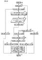
- the optimizer subroutine of Fig. 7 provides optimization in accordance with the present invention.
- the optimizer subroutine is reached through an entry point and a first test 131 determines if a weight of fuel count has reached 300 or not.
- a large number of samples of commanded fuel (WF CMND) are sampled because there is a significant amount of noise on the fuel command (incremental changes therein which are not indicative of engine/aircraft operation). Additionally, the invention takes into account the need for allowing settling at any given level of fuel rate.
- the turbine reference speed is compared with the turbine speed, and if there is error, this is reflected in the gas generator speed command (NF CMND) which in turn results in an increment of fuel flow. This in turn alters the torque being generated by the gas generator and imparted by the free turbine to the rotor. If the rotor changes speed, the automatic flight control system must then adjust the various blade pitch angles to retain trim, altitude and speed. Once this is accomplished, the turbine speed may again adjust (such as in the obvious case of the blade angle of the main rotor being increased by the speed/altitude hold system, the rotor will require more torque, slowing down the turbine, creating a larger error and requiring readjustment).
- NF CMND gas generator speed command
- utilizing a relatively high count taken over a sampling period of on the order of a minute accommodates the acquisition of relatively valid fuel data which eliminates noise considerations.
- providing a settling delay period of on the order of 5 seconds or so, allows reestablishment of desired flight conditions as a result of any perturbation in the reference speed set point. Since the weight of fuel count is initialized to zero in step 127 of Fig. 6, the first pass through the optimizer subroutine of Fig. 7 will always find an affirmative result of test 131. This reaches a test 143 which determines if a settling delay period is complete; since the delay count is initialized to zeros in steps 106 of Fig.
- test 143 the delay count is always zero in the first pass through the optimizer subroutine of Fig. 6.
- An affirmative result of test 143 reaches a step 144 which increments the delay counter, and the NF SET program of Fig. 3 is returned to through a point 134.
- step 135 which provides a current factor of fuel consumption rate, (WF RATE)n which equals the accumulated fuel command weight (as described hereinbefore with respect to step 81 in Fig. 3, but as perfonned during the count period only, in step 132 of Fig. 7) by the number of fuel weight increments included in the accumulation as indicated by the weight of fuel count which is incremented in step 133 of Fig. 7. This gives a fairly accurate representation of the fuel rate across the count period.
- WF RATE current factor of fuel consumption rate
- step 135 can be eliminated if desired, and the accumulation of one cycle could be compared with that of another cycle in the same way that the rate is compared as described hereinafter.
- a real time clock could be utilized to accumulate fuel canmands over a given time period, in one iteration after the other, if desired.
- the fuel consumption rate determined in this iteration is compared in a test 136 with the fuel consumption rate determined in a prior iteration, (WF RATE)n. If the fuel rate were less in this iteration than it was in the prior iteration, this means that the optimizer is working in the right direction so that the sign of an optimum increment of reference speed is also correct. On the other hand, if the current iteration used more fuel than the prior iteration, this iieans that the optimizer is working in the wrong direction. In such a case, a negative result of test 136 will cause a step 137 to reverse the sign of the optimum increment.
- a step 138 causes the last iteration fuel rate to be updated to this iteration fuel rate for use in the subsequent iteration.
- a step 139 adds the optimum increment to the current reference speed and steps 140-142 zero the weight of fuel accumulator and counter and delay counter for use in the next iteration.
- the NF SET program of Fig. 3 is reverted to and the newly incremented speed reference is checked against limits by tests and steps 97-100, as usual.
- the settling period is counted in step 144 and then the fuel increments are accumulated in step 132 and the count is incremented in step 133, after which the fuel rate of that iteration is compared to the fuel rate of the prior iteration, to determine if the sign of the optimum increment should be changed in step 137, and the increment (with or without a change in sign) is added to the previous reference value, NF SET.
- the turbine reference speed is perturbed by 1/4% (or such other increment as is desired) of rated speed once about every minute (or such other suitable time as is established) and the fuel consumption during that minute is compared with the fuel consumption during the prior minute to see if it has improved or not. If it has improved, the sign of the optimum increment remains the same; otherwise, the sign is changed. Ostencibly, assuming perfectly steady state conditions (which of course is impossible in a helicopter driven by a free turbine gas engine) the sign of the optimum increment would change in each iteration. However, the steps are sufficiently small that there is a nearly imperceptible change in engine and helicopter rotor conditions as a consequence thereof; but enough change to affect fuel rate.
- the pilot will engage the cruise mode only when he expects to be cruising in steady flight conditions for one-quarter of an hour or more.
- the optimizer subroutine of Fig. 7 will be controlling the free turbine reference speed as described.
- the pilot may be instructed to alter his flight path as a consequence of heavy traffic conditions, and thereby be required to establish radically new automatic flight control system references. In which case, he may disengage the automatic flight control. Or, the pilot may feel the need to evade a nearby aircraft quickly, by introducing pitch or roll moments through the cyclic pitch stick.
- the cruise control subroutine of Fig. 4 will terminate the cruise mode of engine control operation.
- the pit of simply decides to end the cruise engine control mode he may turn the cruise mode off in which case test 84 will be negative.
- test 102 would be negative.
- test 104 could also be made responsive to collective stick or pedals, though there is little need therefor during cruise, test 104 will be affirmative.
- a first test 146 determines if the fade counter has exceeded 150 counts. Since the fade counter is set to all zeros in step 124 of Fig. 6 during the last pass through the fade-in subroutine, the initial passes through the fade-out subroutine will have an affirmative result of test 146. This reaches a step 147 which increments the fade counter and the NF SET program of Fig. 3 is returned to through a point 148, without altering the speed reference.
- the fade-out subroutine of Fig. 8 will be passed through 150 times (approximately one-half minute in a 200 millisecond machine) while the fade counter is incremented. Eventually, test 146 will be negative reaching a step 149 which will set the fade counter to all zeros. And then the reference speed is examined in a test 150 to see if it exceeds 100% reference speed by more than 1/2%. If it does, a negative result of test 150 will reach a step 151 which decrements the reference speed by 1/2%. On the other hand, if the reference speed is not greater than 1/2% in excess of 100% rated speed, an affirmative result of the test 150 will reach a test 151 where the reference speed is examined to see if it is more than 1/2% below rated speed.
- the rated speed is simply incremented by 1/2% in a step 153. And then the NF SET program of Fig. 3 is returned to through the point 148 and the adjusted reference speed is tested against limits in the tests and steps 97-100 as usual.
- test 89 is affirmative reaching the fade-out subroutine of Fig. 8 in which test 146 is also affirmative so the only activity is incrementing the fade counter in step 147 of Fig. 8. After about one-half minute, the test 146 will again be negative so that the reference point will again be incremented or decremented, if necessary. In some subsequent iteration through Fig.
- test 146 will be negative, test 150 will be affirmative and test 152 will be negative indicating that the reference speed has been adjusted to within 1/2% of 100% rated speed. In such case, a negative result of test 152 will reach a step 154 where the reference speed is reestablished as 100% rated speed, and a step 155 will reset the fade-out required flag.
- the NF SET program of Fig. 3 is returned to through a point 148.
- test 89 will be negative so that the normal routine of Fig. 5 will be utilized, holding the reference speed at 100% rated speed unless the pilot beeps the reference speed up or down, as described hereinbefore.
- a first and important aspect of the present invention is the signal processing illustrated by the exemplary subroutine in Fig. 7.
- the signal processing exemplified therein according to this aspect of the invention takes a large number of samples of a signal indicative of fuel consumption rate; the large number of samples is both sufficient to eliminate noise considerations (on a random, average basis), and to provide adequate time for the adjusted reference speed to effect fuel flow rate, turbine torque, and rotor blade angle requirements, with the turbine torque perturbations feeding back through free turbine speed (NF) and providing a speed error in contrast with the newly established reference speed (that established in step 139 of Fig. 7).
- This aspect of the invention may be used alone, or it may be used along with other aspects of the present invention.
- a second aspect of the present invention is the establishment of a nominal minimum fuel flow rate reference speed by means of a schedule which takes into account the aircraft total weight, speed, altitude and outside air temperature.
- a nominal optimum reference speed by means of the schedule is simply the starting point, and it is used in conjunction with the optimizer aspect of the invention because it is difficult to predict the variations in minimum fuel consumption speed from one aircraft to the next of the same type, due to production tolerances, and for a given aircraft over its life span as rotor and engine performance decay somewhat due to use.
- the second aspect of the invention utilizing a nominal minimum fuel reference speed, may be utilized in a simpler system (one formulated digitally with dedicated hardware, in which optimizing is very difficult, or in an analog system) provided accommodation is made for looking up the desired values in a table.
- a schedule utilizing analog circuitry, such circuitry would be extremely complex and unreliable due to the variations of circuit parameters over periods of time. Thus the fuel savings reliability as compared to cost and complexity would probably not justify an analog variation of the invention.
- the second aspect of the invention (a minimum fuel speed schedule) may be used simply to provide beep-up and beep-down indications to the pilot until he beeps the NF SET to approximately the minimum fuel speed of the schedule.
- a third aspect of the invention is the utilization of fade-in and fade-out between the cruise mode and nonnal reference speed control.
- This aspect of the invention would not be required if the optimizer was to be utilized without utilizing the initializing schedule. This is because of the fact that if the desired, minimum fuel consumption speed were to be reached, the sign of the optimum increment would remain the same through many iterations, and thus the desired reference speed would be approached directly from the nominal reference speed established by the normal part of the program.
- the optimizer may be used alone, the schedule may be used alone as a pilot beep indication or used together with fade-in or fade-out, or all three may be used together as described in the exemplary embodiment herein, or, the pilot could beep to the schedule and the optimizer used thereafter.
- the exemplary embodiment herein is described as being implemented within a program of a digital fuel control 53 (Fig. 1).
- the particular characteristics of the fuel control are irrelevant, so long as it is of the type that uses a turbine reference speed to control fuel flow to the engine.
- the manner in which it controls fuel flow is irrelevant to the present invention.
- the invention is implementable in any digital fuel control directly, provided such digital fuel control includes a mircroprocessor or other computer.
- the invention is readily implemented for use with any fuel control (only the NF SET function thereof 62 being altered by the invention).
- the invention may be practiced in an automatic flight control system canputer, if one is available on board the aircraft.
- Interfacing between the digital fuel control and the automatic flight control system computer is a simple matter as is known in the art. Additionally, the invention may be practiced in a minute microprocesor devoted only to setting reference speed, or with suitable analog-to-digital conversion to an analog fuel control, or with direct digital interfacing with a digital fuel control of any type. All of the cycle times, counts, and the like herein may of course be adjusted to suit any implementation and utilization of the invention.
- the invention although disclosed as it may be implemented in a system having a computer, may also be implemented in dedicated digital hardware in a manner which is an obvious variant of that described herein. However, it is anticipated that dedicated hardware to perform the functions of the invention would be far more costly than utilization of a suitably programmed microprocessor. All of the foregoing is irrelevant to the invention, it suffice to select the aspects thereof and provide suitable signal processing to achieve the desired result in accordance with the invention, in a manner suited to the intended aircraft use.
Landscapes
- Engineering & Computer Science (AREA)
- Combustion & Propulsion (AREA)
- Aviation & Aerospace Engineering (AREA)
- Remote Sensing (AREA)
- Physics & Mathematics (AREA)
- General Physics & Mathematics (AREA)
- Automation & Control Theory (AREA)
- Radar, Positioning & Navigation (AREA)
- Chemical & Material Sciences (AREA)
- General Engineering & Computer Science (AREA)
- Mechanical Engineering (AREA)
- Control Of Turbines (AREA)
- Control Of Vehicle Engines Or Engines For Specific Uses (AREA)
- Electrical Control Of Air Or Fuel Supplied To Internal-Combustion Engine (AREA)
- Toys (AREA)
- Catching Or Destruction (AREA)
Applications Claiming Priority (2)
| Application Number | Priority Date | Filing Date | Title |
|---|---|---|---|
| US06/369,302 US4488236A (en) | 1982-04-16 | 1982-04-16 | Helicopter cruise fuel conserving engine control |
| US369302 | 1982-04-16 |
Publications (3)
| Publication Number | Publication Date |
|---|---|
| EP0092501A2 true EP0092501A2 (de) | 1983-10-26 |
| EP0092501A3 EP0092501A3 (en) | 1984-01-04 |
| EP0092501B1 EP0092501B1 (de) | 1988-06-08 |
Family
ID=23454908
Family Applications (1)
| Application Number | Title | Priority Date | Filing Date |
|---|---|---|---|
| EP83630062A Expired EP0092501B1 (de) | 1982-04-16 | 1983-04-15 | Helikoptermotorsteuerung zum Brennstoffsparen im stationären Flug |
Country Status (6)
| Country | Link |
|---|---|
| US (1) | US4488236A (de) |
| EP (1) | EP0092501B1 (de) |
| JP (1) | JPS58190526A (de) |
| CA (1) | CA1198192A (de) |
| DE (1) | DE3376992D1 (de) |
| IL (1) | IL68409A (de) |
Cited By (2)
| Publication number | Priority date | Publication date | Assignee | Title |
|---|---|---|---|---|
| EP0398840A3 (de) * | 1989-05-19 | 1992-01-08 | United Technologies Corporation | Hubschrauber mit Erhöhung der Rotorgeschwindigkeit bei Hochbelastung |
| EP1749995A3 (de) * | 2005-08-03 | 2010-04-28 | Candent Technologies, Inc. | Gasturbinensystem mit mehreren Wellen |
Families Citing this family (21)
| Publication number | Priority date | Publication date | Assignee | Title |
|---|---|---|---|---|
| GB2185951B (en) * | 1986-02-04 | 1989-07-05 | Rolls Royce | Helicopter rotor and engine control |
| US4817046A (en) * | 1986-04-10 | 1989-03-28 | United Technologies Corporation | Detection of engine failure in a multi-engine aircraft |
| CH671555A5 (de) * | 1986-09-10 | 1989-09-15 | Zermatt Air Ag | |
| US5023797A (en) * | 1989-05-19 | 1991-06-11 | United Technologies Corporation | Range maximizing, stable, helicopter cruise fuel conservation |
| DE4040796A1 (de) * | 1990-12-17 | 1992-07-02 | Mannesmann Ag | Verfahren zur adaptiven regelung positionierbarer antriebe |
| US5265826A (en) * | 1991-08-27 | 1993-11-30 | United Technologies Corporation | Helicopter engine control having lateral cyclic pitch anticipation |
| US5265825A (en) * | 1991-08-27 | 1993-11-30 | United Technologies Corporation | Helicopter engine control having yaw input anticipation |
| US6748744B2 (en) | 2001-11-21 | 2004-06-15 | Pratt & Whitney Canada Corp. | Method and apparatus for the engine control of output shaft speed |
| EP1560338A1 (de) * | 2004-01-27 | 2005-08-03 | Siemens Aktiengesellschaft | Verfahren zur Speicherung von Prozesssignalen einer technischen Anlage |
| US7546975B2 (en) * | 2004-09-14 | 2009-06-16 | The Boeing Company | Tandem rotor wing rotational position control system |
| US7949440B2 (en) * | 2006-12-22 | 2011-05-24 | Embraer-Empresa Brasileira De Aeronautica S.A. | Aircraft cruise speed control |
| US8566000B2 (en) | 2010-02-23 | 2013-10-22 | Williams International Co., L.L.C. | System and method for controlling a single-spool turboshaft engine |
| FR2964155B1 (fr) * | 2010-08-25 | 2014-03-28 | Turbomeca | Procede d'optimisation de regulation d'un groupe de puissance a turbine libre pour aeronef et commande de regulation de mise en oeuvre |
| JP5725659B2 (ja) * | 2011-08-29 | 2015-05-27 | 本田技研工業株式会社 | 車両の瞬間燃費表示装置 |
| US10864986B2 (en) * | 2015-03-23 | 2020-12-15 | Sikorsky Aircraft Corporation | Aerial vehicle including autonomous rotor speed control |
| US11987375B2 (en) | 2019-02-08 | 2024-05-21 | Pratt & Whitney Canada Corp. | System and method for operating engines of an aircraft in an asymmetric operating regime |
| US11725597B2 (en) | 2019-02-08 | 2023-08-15 | Pratt & Whitney Canada Corp. | System and method for exiting an asymmetric engine operating regime |
| FR3110545B1 (fr) | 2020-05-20 | 2022-04-29 | Airbus Helicopters | Procédé d’optimisation d’une consommation d’énergie d’un hélicoptère hybride en vol en palier |
| WO2021263163A1 (en) * | 2020-06-26 | 2021-12-30 | Hedrick Geoffrey S M | Aircraft control for endurance and fuel economy |
| FR3115825A1 (fr) * | 2020-11-04 | 2022-05-06 | Airbus Helicopters | Procédé de pilotage d’une installation motrice d’un giravion comprenant au moins deux turbomoteurs |
| CN113190044B (zh) * | 2021-05-08 | 2022-12-30 | 一飞(海南)科技有限公司 | 集群表演无人机起飞控制方法、系统、介质、终端及无人机 |
Family Cites Families (8)
| Publication number | Priority date | Publication date | Assignee | Title |
|---|---|---|---|---|
| FR1481955A (fr) * | 1965-12-30 | 1967-05-26 | Snecma | Dispositif réduisant la consommation de car burant des avions en croisière |
| US4038526A (en) * | 1967-12-29 | 1977-07-26 | The Secretary Of State For Defence In Her Britanic Majesty's Government Of The United Kingdom Of Great Britain And Northern Ireland | Optimizing control system for aircraft |
| FR2180182A5 (de) * | 1972-04-12 | 1973-11-23 | Sopromi Soc Proc Modern Inject | |
| CH584940A5 (de) * | 1974-08-07 | 1977-02-15 | Soechtig Gerhard | |
| US4159088A (en) * | 1977-01-03 | 1979-06-26 | The Boeing Company | System for reducing aircraft fuel consumption |
| US4325123A (en) * | 1978-07-28 | 1982-04-13 | The Boeing Company | Economy performance data avionic system |
| JPS55134732A (en) * | 1979-04-04 | 1980-10-20 | Nippon Denso Co Ltd | Optimal controlling method of engine |
| GB2052805B (en) * | 1979-06-29 | 1983-03-09 | Smiths Industries Ltd | Gas-turbine engine control |
-
1982
- 1982-04-16 US US06/369,302 patent/US4488236A/en not_active Expired - Lifetime
-
1983
- 1983-04-12 CA CA000425723A patent/CA1198192A/en not_active Expired
- 1983-04-14 IL IL6840983A patent/IL68409A/en not_active IP Right Cessation
- 1983-04-15 JP JP58066826A patent/JPS58190526A/ja active Granted
- 1983-04-15 EP EP83630062A patent/EP0092501B1/de not_active Expired
- 1983-04-15 DE DE8383630062T patent/DE3376992D1/de not_active Expired
Cited By (3)
| Publication number | Priority date | Publication date | Assignee | Title |
|---|---|---|---|---|
| EP0398840A3 (de) * | 1989-05-19 | 1992-01-08 | United Technologies Corporation | Hubschrauber mit Erhöhung der Rotorgeschwindigkeit bei Hochbelastung |
| EP1749995A3 (de) * | 2005-08-03 | 2010-04-28 | Candent Technologies, Inc. | Gasturbinensystem mit mehreren Wellen |
| US8220245B1 (en) | 2005-08-03 | 2012-07-17 | Candent Technologies, Inc. | Multi spool gas turbine system |
Also Published As
| Publication number | Publication date |
|---|---|
| IL68409A (en) | 1996-03-31 |
| DE3376992D1 (en) | 1988-07-14 |
| CA1198192A (en) | 1985-12-17 |
| US4488236A (en) | 1984-12-11 |
| EP0092501B1 (de) | 1988-06-08 |
| JPS58190526A (ja) | 1983-11-07 |
| JPH0416619B2 (de) | 1992-03-24 |
| EP0092501A3 (en) | 1984-01-04 |
Similar Documents
| Publication | Publication Date | Title |
|---|---|---|
| US4488236A (en) | Helicopter cruise fuel conserving engine control | |
| EP0093684B1 (de) | Hubschraubermotorsteuerung mit Vorhersage des Abklingens der Rotorgeschwindigkeit | |
| US3932058A (en) | Control system for variable pitch fan propulsor | |
| EP0092502B1 (de) | Kraftstoffsteuerung zum Steuern der Rotor-/Turbinenbeschleunigung von Helikoptern | |
| US8651811B2 (en) | Control logic for a propeller system | |
| EP0601100B1 (de) | Hubschraubermotorsteuerung mit von der zyklischen blattwinkeländerung in querrichtung abhängigem vorhersagewert | |
| US12054245B2 (en) | Optimizing usage of supplemental engine power | |
| KR100235271B1 (ko) | 요우(yaw)입력 예측 기능을 가지는 헬리콥터 | |
| JP3294270B2 (ja) | 高回転翼負荷及び急速降下速度操作中のヘリコプタエンジン速度増大 | |
| US12078074B2 (en) | System and method for detecting an uncommanded or uncontrollable high thrust event in an aircraft | |
| US4998202A (en) | Helicopter, high rotor load speed enhancement | |
| JPS6076499A (ja) | 可変ピツチプロペラのピツチ制御方法及びその制御装置 | |
| CN111102079A (zh) | 以涡轮螺旋桨为动力的飞行器上的自动油门控制系统 | |
| CA1246717A (en) | Rotorcraft load factor enhancer | |
| US5023797A (en) | Range maximizing, stable, helicopter cruise fuel conservation | |
| EP4154098B1 (de) | Flugzeugsteuerung für ausdauer und kraftstoffeinsparung | |
| US20200370510A1 (en) | Method and system for operating an aircraft powerplant | |
| RU2774495C1 (ru) | Способ пилотирования гибридного вертолета, имеющего планер, удерживаемый с постоянным углом атаки посредством регулирования положения по меньшей мере одной подвижной плоскости оперения | |
| Ruttledge | A rotorcraft flight/propulsion control integration study | |
| Mihaloew et al. | Rotorcraft flight-propulsion control integration: An eclectic design concept | |
| Swick et al. | Investigation of Coordinated Free Turbine Engine Control Systems for Multiengine Helicopters | |
| Chiuchiolo et al. | Three-engine control system for the prototype EH-101 helicopter | |
| Zabinsky | The Effect of Propulsion System Parameters on Vertical Take-Off and Landing Performance of a Transport Aircraft |
Legal Events
| Date | Code | Title | Description |
|---|---|---|---|
| PUAI | Public reference made under article 153(3) epc to a published international application that has entered the european phase |
Free format text: ORIGINAL CODE: 0009012 |
|
| AK | Designated contracting states |
Designated state(s): DE FR GB IT |
|
| PUAL | Search report despatched |
Free format text: ORIGINAL CODE: 0009013 |
|
| AK | Designated contracting states |
Designated state(s): DE FR GB IT |
|
| 17P | Request for examination filed |
Effective date: 19840224 |
|
| GRAA | (expected) grant |
Free format text: ORIGINAL CODE: 0009210 |
|
| AK | Designated contracting states |
Kind code of ref document: B1 Designated state(s): DE FR GB IT |
|
| REF | Corresponds to: |
Ref document number: 3376992 Country of ref document: DE Date of ref document: 19880714 |
|
| ET | Fr: translation filed | ||
| ITF | It: translation for a ep patent filed | ||
| PLBE | No opposition filed within time limit |
Free format text: ORIGINAL CODE: 0009261 |
|
| STAA | Information on the status of an ep patent application or granted ep patent |
Free format text: STATUS: NO OPPOSITION FILED WITHIN TIME LIMIT |
|
| 26N | No opposition filed | ||
| ITTA | It: last paid annual fee | ||
| REG | Reference to a national code |
Ref country code: GB Ref legal event code: IF02 |
|
| PGFP | Annual fee paid to national office [announced via postgrant information from national office to epo] |
Ref country code: FR Payment date: 20020311 Year of fee payment: 20 |
|
| PGFP | Annual fee paid to national office [announced via postgrant information from national office to epo] |
Ref country code: GB Payment date: 20020313 Year of fee payment: 20 |
|
| PGFP | Annual fee paid to national office [announced via postgrant information from national office to epo] |
Ref country code: DE Payment date: 20020314 Year of fee payment: 20 |
|
| PG25 | Lapsed in a contracting state [announced via postgrant information from national office to epo] |
Ref country code: GB Free format text: LAPSE BECAUSE OF EXPIRATION OF PROTECTION Effective date: 20030414 |
|
| REG | Reference to a national code |
Ref country code: GB Ref legal event code: PE20 |