EP0092301A2 - Electrical shorting switch assemblies - Google Patents
Electrical shorting switch assemblies Download PDFInfo
- Publication number
- EP0092301A2 EP0092301A2 EP83300768A EP83300768A EP0092301A2 EP 0092301 A2 EP0092301 A2 EP 0092301A2 EP 83300768 A EP83300768 A EP 83300768A EP 83300768 A EP83300768 A EP 83300768A EP 0092301 A2 EP0092301 A2 EP 0092301A2
- Authority
- EP
- European Patent Office
- Prior art keywords
- switch
- last
- operating shaft
- open
- arcing
- Prior art date
- Legal status (The legal status is an assumption and is not a legal conclusion. Google has not performed a legal analysis and makes no representation as to the accuracy of the status listed.)
- Granted
Links
- 230000000712 assembly Effects 0.000 title description 3
- 238000000429 assembly Methods 0.000 title description 3
- 238000010587 phase diagram Methods 0.000 description 4
- RYGMFSIKBFXOCR-UHFFFAOYSA-N Copper Chemical compound [Cu] RYGMFSIKBFXOCR-UHFFFAOYSA-N 0.000 description 1
- QAAXRTPGRLVPFH-UHFFFAOYSA-N [Bi].[Cu] Chemical compound [Bi].[Cu] QAAXRTPGRLVPFH-UHFFFAOYSA-N 0.000 description 1
- 239000000956 alloy Substances 0.000 description 1
- 229910045601 alloy Inorganic materials 0.000 description 1
- 238000010276 construction Methods 0.000 description 1
- 229910052802 copper Inorganic materials 0.000 description 1
- 239000010949 copper Substances 0.000 description 1
- 230000008878 coupling Effects 0.000 description 1
- 238000010168 coupling process Methods 0.000 description 1
- 238000005859 coupling reaction Methods 0.000 description 1
- 230000000694 effects Effects 0.000 description 1
- 230000001939 inductive effect Effects 0.000 description 1
- 229910052751 metal Inorganic materials 0.000 description 1
- 239000002184 metal Substances 0.000 description 1
Images


Classifications
-
- H—ELECTRICITY
- H01—ELECTRIC ELEMENTS
- H01H—ELECTRIC SWITCHES; RELAYS; SELECTORS; EMERGENCY PROTECTIVE DEVICES
- H01H33/00—High-tension or heavy-current switches with arc-extinguishing or arc-preventing means
- H01H33/002—Very heavy-current switches
-
- H—ELECTRICITY
- H01—ELECTRIC ELEMENTS
- H01H—ELECTRIC SWITCHES; RELAYS; SELECTORS; EMERGENCY PROTECTIVE DEVICES
- H01H9/00—Details of switching devices, not covered by groups H01H1/00 - H01H7/00
- H01H9/30—Means for extinguishing or preventing arc between current-carrying parts
-
- H—ELECTRICITY
- H01—ELECTRIC ELEMENTS
- H01H—ELECTRIC SWITCHES; RELAYS; SELECTORS; EMERGENCY PROTECTIVE DEVICES
- H01H1/00—Contacts
- H01H1/58—Electric connections to or between contacts; Terminals
- H01H1/5822—Flexible connections between movable contact and terminal
- H01H2001/5827—Laminated connections, i.e. the flexible conductor is composed of a plurality of thin flexible conducting layers
Definitions
- the invention relates to electrical shorting switch assemblies such as are used as by-pass switches for electrolytic cells in a variety of electrochemical processing plants.
- the shorting switch assembly will typically include a plurality of hermetically sealed electrical switch members which provide electrically parallel current paths to handle the very large bypass current levels which are typically employed in electrolytic cells.
- Such an electrical shorting switch assembly is seen in detail in U.S. Patent Specification No. 4,216,359, owned by the assignee of the present invention and the teachings of which are hereby incorporated by reference.
- the individual electrically parallelled switches which make up the shorting switch detailed in the aforementioned patent are operated off of a common rotatable operating shaft and are more or less simultaneously opened and closed.
- an auxiliary arc contact switch had been employed as one of the switches of a shorting switch assembly to absorb the inductive energy of the bypassed or switched circuit.
- Such an auxiliary arcing switch in order to be effective must open after the other switches have opened and such a sequential switch opening can be provided by a phased cam system, such as seen in U.S. Patent Specification No. 4,121,268, owned by the assignee of the present invention.
- the shorting switch assemblies described above utilize a rotatable shaft to reciprocate a switch opening and closing means, and this means that arc contacts which are the last to open would then be the first to close when the shorting switch is actuated to return the current to the electrolytic cell. This causes the arcing switch contacts to carry very high current loads and can occasionally result in failure of the arcing switch.
- an electrical shorting switch assembly for connection across an electrolytic cell as a by-pass shorting switch in parallel with the electrolytic cell and which comprises at least two electrically paralleled hermetically sealed switch modules, one of which switch modules is a last-to-open and last-to-close arcing switch module; and means for sequentially operating the respective switch modules.
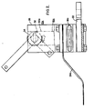
- Electrical shorting switch assembly 10 is best seen in Figure 1 wherein three switch modules 12a, 12b and 12c are connected to a common rotatable operating shaft 14 via respective reciprocal linking means 16a, 16b, 16c.
- the construction and operation of the main current-carrying switch modules 12b and 12c and their respective linking means 16b and 16c and rotatable operating shaft 14 are described in detail in the aforementioned U.S. Patent Specification No. 4,216,359.
- the switch modules 12b and 12c include hermetically sealed electrical switch members 18b and 18c having flexible diaphragm end portions which permit reciprocal relative motion between the contacts 23 which are shown in phantom in the closed position in Figure 1.
- the lower contacts of switches 18b and 18c are connected via mounting plates 21 to a common bus 22 which extends in a direction out of the drawing and is connectable to one side of the electrolytic cell which is to be bypassed.
- the upper contacts of switch members 18b and 18c are connected via flexible buses 24b, 24c which are connectable to the other terminal of the electrolytic cell.
- the lower contacts of the switch members 18b and 18c are held relatively fixed via the common bus 22 and a rigid frame member 26 from which is mounted the operating shaft 14, so that reciprocation of the linking means 16b and 16c causes reciprocal motion to make and break contact within the hermetically sealed switches.
- the linking means 16b and 16c which couple the switch members 18b and 18c to the rotatable operating shaft 14 are described in greater detail in the aforementioned U.S. Patent Specification No. 4,216,359 with the rotational movement of the shaft 14 converted to a reciprocal force acting on the switch via eccentric cam members 28b and 28c which are mounted on the shaft and coupled to the elongated links 30b and 30c.
- the switch members 18b and 18c are approximately simultaneously opened and closed and are the main current-carrying paths during shunting or bypassing of the electrolytic cell with a low DC voltage of less than ten volts across the shorting switch and with a total DC current of tens of thousands of amperes passing through the parallel path switches.
- Switch module 12a includes arcing switch member 18a and a linking means 16a coupling the arcing switch member 18a to the common shaft 14.
- the switch member 18a is electrically connected in parallel with switch members 18b and 18c, with the lower contact connected via mounting plate to the common bus 22.
- the upper contact of the switch member 18a is also connected to a flexible bus 24a which is connectable to one terminal of the electrolytic cell commonly connected to the flexible buses 24b and 24c.
- the flexible bus 24a is much thinner than the flexible buses 24b and 24c, because the arc switch 18a need only carry the bypass current for a short period, typically less than 50 milliseconds, and because of the sequential operation and contact opening and closing of arc switch member 18a relative to the switch members 18b and 18c as will be explained hereafter.
- the physical structure of the arcing switch is the same as the current-carrying switch.
- the electrical contacts within the switch are however formed of conductive metal or alloys which are varied from copper or copper-bismuth high conductivity current-carrying contacts
- the arc switch module 12a is perhaps best seen and understood in Figure 2, wherein the linking means 16a associated with switch module 12a can be appreciated in this end view.
- the linking means 16a associated with the arcing module 12a is operable to insure that the arc switch is the last-to-open and last-to-close contact in the parallel path shorting switch assembly.
- the arc contact linking means 16a is also seen in various operative positions in Figures 3 through 6.
- the arc contact linking means 16a comprises a pair of spaced-apart insulating links 30a, 30aa, each having elongated apertures 31 provided therethrough to permit the rotatable shaft 14 to pass therethrough.
- the linking means 16a includes a lost motion drive means which is provided via a generally C-shaped ring member 32 which is mounted about shaft 14 between spaced-apart links 30a, 30aa.
- a radially extending drive pin 34 extends from the shaft 14 in the gap of the C-shaped member 32 and acts as a stop means and drive means as will be explained hereafter.
- An inclined cam slot 36 is provided in each of the links 30a, 30aa notched end notch portions 38a, 38b with respective cam follower wheels 40a, 40b fitted in cam slot 36 with a common axle 42 connecting the cam follower wheels, which axle 42 is mounted on the perimeter of the Cshaped member 32.
- the operation of the shorting switch assembly 10 can be appreciated by reference to Figures 3 to 6 which illustrate the operation of the lost motion means and the arcing switch module 12a.
- the arcing switch linking means 16a is seen in the open switch position in Figure 3 with the shaft 14 disposed in the lower portion of the elongated openings and the linking means and with drive pin 34 in a generally vertical direction acting as a stop against the C-shaped member 32.
- the cam follower wheels 40 are disposed in the lower notched end 38a of the inclined cam slot 36, which notch serves as a latching means which requires sufficient force to move the cam wheels out of the notch before the contact can be moved from either the open position or the closed position.
- linking means 16a When the arc contacts of arc switch member 18a are to be opened the linking means 16a operates in the fashion seen in Figure 6 wherein the shaft 14 is rotated clockwise, with clockwise movement of the drive pin 34 engaging the other end of the C-shaped member and forcing axle 42 and cam follower wheels out of the upper end notch 38b in a downwardly inclined direction in cam slot 36.
- the linking means 16a is seen in Figure 6 in a position where the contacts have just separated and prior to further rotation in a clockwise direction to the fully open position as seen in Figure 3.
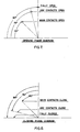
- FIGS 7 and 8 are respectively opening phase diagrams and closing phase diagrams, in which the respective timed operation of the switch opening and closing are seen.
- FIGs 7 and 8 further illustrate the last-to-open and last-to-close arcing switch module operation compared to the current carrying switch modules.
- the opening phase diagram seen in Figure 7 illustrates when the operating shaft rotates through an angle from the horizontal closed position of 45 degrees, the main current-carrying switch members 18b and 18c open and a further shaft rotation to the 75 degree position causes the arc contacts of the arc switch member 18a to open or separate.
- the fully opened arc contact position occurs at the 90 degree angular rotation position at which time the cam wheels are locked in the notch for fully opened latched operation.
Landscapes
- Driving Mechanisms And Operating Circuits Of Arc-Extinguishing High-Tension Switches (AREA)
- Arc-Extinguishing Devices That Are Switches (AREA)
- Slide Switches (AREA)
Abstract
Description
- The invention relates to electrical shorting switch assemblies such as are used as by-pass switches for electrolytic cells in a variety of electrochemical processing plants. The shorting switch assembly will typically include a plurality of hermetically sealed electrical switch members which provide electrically parallel current paths to handle the very large bypass current levels which are typically employed in electrolytic cells. Such an electrical shorting switch assembly is seen in detail in U.S. Patent Specification No. 4,216,359, owned by the assignee of the present invention and the teachings of which are hereby incorporated by reference. The individual electrically parallelled switches which make up the shorting switch detailed in the aforementioned patent are operated off of a common rotatable operating shaft and are more or less simultaneously opened and closed. In some cases an auxiliary arc contact switch had been employed as one of the switches of a shorting switch assembly to absorb the inductive energy of the bypassed or switched circuit. Such an auxiliary arcing switch in order to be effective must open after the other switches have opened and such a sequential switch opening can be provided by a phased cam system, such as seen in U.S. Patent Specification No. 4,121,268, owned by the assignee of the present invention.
- The shorting switch assemblies described above utilize a rotatable shaft to reciprocate a switch opening and closing means, and this means that arc contacts which are the last to open would then be the first to close when the shorting switch is actuated to return the current to the electrolytic cell. This causes the arcing switch contacts to carry very high current loads and can occasionally result in failure of the arcing switch.
- It is desirable to provide an electrical shorting switch assembly which utilizes an arcing switch in a parallel path with one or more normal current-carrying switches, with the arc switch being both a last-to-open and last-to-close switch in the assembly.
- It is desirable that electrical shorting switches be latched while in the open or closed position to prevent accidental switch actuation. A positive switch actuation force should be required to open or close the shorting switch.
- Accordingly the present invention resides in an electrical shorting switch assembly for connection across an electrolytic cell as a by-pass shorting switch in parallel with the electrolytic cell and which comprises at least two electrically paralleled hermetically sealed switch modules, one of which switch modules is a last-to-open and last-to-close arcing switch module; and means for sequentially operating the respective switch modules.
- It has been found convenient to couple a common rotatable operating shaft to the means for sequentially operating the respective switch modules which preferably includes a last-motion means coupled between the operating shaft and the arcing switch module.
- In order that the invention can be more clearly understood, a convenient embodiment thereof will now be described, by way of example, with reference to the accompanying drawings in which:
- Figure 1 is a side elevational view of an electrical shorting switch assembly including the operating means,
- Figure 2 is an end view taken in the direction of line II of Figure 1,
- Figure 3 is an enlarged representation of the reciprocal linking means and lost motion means in the switch open position,
- Figure 4 is an enlarged representation of the reciprocating linking means and lost motion means in the switch position where the arc contacts have first met during a closing operation,
- Figure 5 is an enlarged representation of the reciprocating means and lost motion means in the switch closed position,
- Figure 6 is an enlarged representation of the reciprocating means and lost motion means in the switch position where the contacts first separate during an opening operation,
- Figure 7 is a graphical representation illustrating the angular rotation of the operating shaft and lost motion means during an arc switch opening operation, and
- Figure 8 is a graphical representation illustrating the angular rotation of the operating shaft and lost motion means during an arc switch closing operation.
- Electrical
shorting switch assembly 10 is best seen in Figure 1 wherein threeswitch modules rotatable operating shaft 14 via respective reciprocal linking means 16a, 16b, 16c. The construction and operation of the main current-carryingswitch modules rotatable operating shaft 14 are described in detail in the aforementioned U.S. Patent Specification No. 4,216,359. Theswitch modules electrical switch members contacts 23 which are shown in phantom in the closed position in Figure 1. The lower contacts ofswitches mounting plates 21 to acommon bus 22 which extends in a direction out of the drawing and is connectable to one side of the electrolytic cell which is to be bypassed. The upper contacts ofswitch members flexible buses switch members common bus 22 and arigid frame member 26 from which is mounted theoperating shaft 14, so that reciprocation of the linking means 16b and 16c causes reciprocal motion to make and break contact within the hermetically sealed switches. - The linking means 16b and 16c which couple the
switch members rotatable operating shaft 14 are described in greater detail in the aforementioned U.S. Patent Specification No. 4,216,359 with the rotational movement of theshaft 14 converted to a reciprocal force acting on the switch viaeccentric cam members elongated links switch members - Switch module 12a includes arcing switch member 18a and a linking means 16a coupling the arcing switch member 18a to the
common shaft 14. The switch member 18a is electrically connected in parallel withswitch members common bus 22. The upper contact of the switch member 18a is also connected to a flexible bus 24a which is connectable to one terminal of the electrolytic cell commonly connected to theflexible buses flexible buses switch members - The arc switch module 12a is perhaps best seen and understood in Figure 2, wherein the linking means 16a associated with switch module 12a can be appreciated in this end view. The linking means 16a associated with the arcing module 12a is operable to insure that the arc switch is the last-to-open and last-to-close contact in the parallel path shorting switch assembly. The arc contact linking means 16a is also seen in various operative positions in Figures 3 through 6. The arc contact linking means 16a comprises a pair of spaced-apart insulating links 30a, 30aa, each having
elongated apertures 31 provided therethrough to permit therotatable shaft 14 to pass therethrough. The linking means 16a includes a lost motion drive means which is provided via a generally C-shaped ring member 32 which is mounted aboutshaft 14 between spaced-apart links 30a, 30aa. A radially extendingdrive pin 34 extends from theshaft 14 in the gap of the C-shaped member 32 and acts as a stop means and drive means as will be explained hereafter. Aninclined cam slot 36 is provided in each of the links 30a, 30aa notchedend notch portions 38a, 38b with respectivecam follower wheels 40a, 40b fitted incam slot 36 with acommon axle 42 connecting the cam follower wheels, whichaxle 42 is mounted on the perimeter of the Cshapedmember 32. - The operation of the
shorting switch assembly 10 can be appreciated by reference to Figures 3 to 6 which illustrate the operation of the lost motion means and the arcing switch module 12a. The arcing switch linking means 16a is seen in the open switch position in Figure 3 with theshaft 14 disposed in the lower portion of the elongated openings and the linking means and withdrive pin 34 in a generally vertical direction acting as a stop against the C-shaped member 32. The cam follower wheels 40 are disposed in the lower notched end 38a of theinclined cam slot 36, which notch serves as a latching means which requires sufficient force to move the cam wheels out of the notch before the contact can be moved from either the open position or the closed position. When the arc switch 18a is to be closed along with the closing ofswitch members shorting switch assembly 10 bypasses the electrolytic cell and provides a plurality of parallel current paths through the respective switch members, theoperating shaft 14 is rotated as seen in Figure 4 counterclockwise. The drive pin in moving through the gap area of the C-shaped means 32 provides a lost motion mechanism with the contacts of the arcing switch 18a remaining open while the contacts of the main current-carryingswitch members drive pin 34 is rotated so as to contact the end of the C-shaped member 32 and to force it to rotate again counterclockwise, this forces theaxle 42 mounted on the perimeter of the C-shaped member to force the cam wheels out of the end notch in an upward inclined direction along thecam slot 36. The position of the cam wheels as seen in Figure 4 is generally as the arc contacts of arc switch 18a are meeting. The arc switch member 18a is seen in Figure 5 in the fully closed position wherein thedrive pin 34 has been further rotated in a counterclockwise direction so that it is basically horizontal and the cam follower wheels 40 have been moved to the upper end of thecam slot 36 and are inupper end notch 38b. When the arc contacts of arc switch member 18a are to be opened the linking means 16a operates in the fashion seen in Figure 6 wherein theshaft 14 is rotated clockwise, with clockwise movement of thedrive pin 34 engaging the other end of the C-shaped member and forcingaxle 42 and cam follower wheels out of theupper end notch 38b in a downwardly inclined direction incam slot 36. The linking means 16a is seen in Figure 6 in a position where the contacts have just separated and prior to further rotation in a clockwise direction to the fully open position as seen in Figure 3. - The operation of the
shorting switch assembly 10 can be further appreciated by reference to Figures 7 and 8 which are respectively opening phase diagrams and closing phase diagrams, in which the respective timed operation of the switch opening and closing are seen. These Figures further illustrate the last-to-open and last-to-close arcing switch module operation compared to the current carrying switch modules. The opening phase diagram seen in Figure 7 illustrates when the operating shaft rotates through an angle from the horizontal closed position of 45 degrees, the main current-carryingswitch members switch members
Claims (5)
Applications Claiming Priority (2)
| Application Number | Priority Date | Filing Date | Title |
|---|---|---|---|
| US06/349,484 US4438302A (en) | 1982-02-17 | 1982-02-17 | Electrical shorting switch assembly including a last to open last to close arcing switch |
| US349484 | 1982-02-17 |
Publications (3)
| Publication Number | Publication Date |
|---|---|
| EP0092301A2 true EP0092301A2 (en) | 1983-10-26 |
| EP0092301A3 EP0092301A3 (en) | 1986-02-26 |
| EP0092301B1 EP0092301B1 (en) | 1989-03-15 |
Family
ID=23372587
Family Applications (1)
| Application Number | Title | Priority Date | Filing Date |
|---|---|---|---|
| EP83300768A Expired EP0092301B1 (en) | 1982-02-17 | 1983-02-16 | Electrical shorting switch assemblies |
Country Status (8)
| Country | Link |
|---|---|
| US (1) | US4438302A (en) |
| EP (1) | EP0092301B1 (en) |
| JP (1) | JPS58152313A (en) |
| KR (1) | KR840003912A (en) |
| CA (1) | CA1196365A (en) |
| DE (1) | DE3379436D1 (en) |
| IN (1) | IN158320B (en) |
| ZA (1) | ZA83605B (en) |
Families Citing this family (4)
| Publication number | Priority date | Publication date | Assignee | Title |
|---|---|---|---|---|
| US6525650B1 (en) * | 1999-06-11 | 2003-02-25 | Trw Inc. | Electronic switching matrix |
| US6713679B2 (en) | 2001-09-25 | 2004-03-30 | Hubbell Incorporated | Terminal pad for an insulator assembly |
| AU2003291556A1 (en) * | 2002-11-21 | 2004-06-18 | Harry H. J. Bang | Electrical switch and method |
| US7247805B2 (en) * | 2005-08-10 | 2007-07-24 | Bendix Commercial Vehicle Systems Llc | Switch actuation method and mechanism |
Citations (4)
| Publication number | Priority date | Publication date | Assignee | Title |
|---|---|---|---|---|
| FR2132905A1 (en) * | 1971-04-07 | 1972-11-24 | Kafak Ab | |
| GB1478837A (en) * | 1974-04-19 | 1977-07-06 | Imi Santon Ltd | Fuse-switches |
| FR2383514A1 (en) * | 1977-03-10 | 1978-10-06 | Westinghouse Electric Corp | VACUUM BREAKING PLANT |
| US4216359A (en) * | 1976-01-19 | 1980-08-05 | Westinghouse Electric Corp. | Low voltage vacuum switch and operating mechanism |
-
1982
- 1982-02-17 US US06/349,484 patent/US4438302A/en not_active Expired - Fee Related
-
1983
- 1983-01-25 CA CA000420140A patent/CA1196365A/en not_active Expired
- 1983-01-27 IN IN103/CAL/83A patent/IN158320B/en unknown
- 1983-01-28 ZA ZA83605A patent/ZA83605B/en unknown
- 1983-02-16 KR KR1019830000622A patent/KR840003912A/en not_active Application Discontinuation
- 1983-02-16 EP EP83300768A patent/EP0092301B1/en not_active Expired
- 1983-02-16 DE DE8383300768T patent/DE3379436D1/en not_active Expired
- 1983-02-17 JP JP58025474A patent/JPS58152313A/en active Pending
Patent Citations (4)
| Publication number | Priority date | Publication date | Assignee | Title |
|---|---|---|---|---|
| FR2132905A1 (en) * | 1971-04-07 | 1972-11-24 | Kafak Ab | |
| GB1478837A (en) * | 1974-04-19 | 1977-07-06 | Imi Santon Ltd | Fuse-switches |
| US4216359A (en) * | 1976-01-19 | 1980-08-05 | Westinghouse Electric Corp. | Low voltage vacuum switch and operating mechanism |
| FR2383514A1 (en) * | 1977-03-10 | 1978-10-06 | Westinghouse Electric Corp | VACUUM BREAKING PLANT |
Also Published As
| Publication number | Publication date |
|---|---|
| US4438302A (en) | 1984-03-20 |
| CA1196365A (en) | 1985-11-05 |
| EP0092301A3 (en) | 1986-02-26 |
| ZA83605B (en) | 1983-12-28 |
| EP0092301B1 (en) | 1989-03-15 |
| DE3379436D1 (en) | 1989-04-20 |
| JPS58152313A (en) | 1983-09-09 |
| IN158320B (en) | 1986-10-18 |
| KR840003912A (en) | 1984-10-04 |
Similar Documents
| Publication | Publication Date | Title |
|---|---|---|
| US5424701A (en) | Operating mechanism for high ampere-rated circuit breakers | |
| RU2298853C2 (en) | Automatic low voltage switch | |
| US6689979B1 (en) | Switching contact arrangement of a low voltage circuit breaker with main contacts, intermediate contact and arcing contacts | |
| US3832504A (en) | Circuit breaker with spring closing means and pawl and rachet spring charging means | |
| EP0092301B1 (en) | Electrical shorting switch assemblies | |
| CA1074372A (en) | Low voltage vacuum switch and operating mechanism | |
| US5489755A (en) | Handle operator assembly for high ampere-rated circuit breaker | |
| US3174000A (en) | Arc resistant switch | |
| US5294903A (en) | Electric switch, in particular a load switch or electric circuit breaker | |
| US4370530A (en) | Electrolytic cell electrical shunting switch assembly | |
| WO1996038851A1 (en) | Electromagnetic switch | |
| EP4318519A1 (en) | Test button loop device and circuit breaker | |
| US4713500A (en) | Electric bypass switch | |
| US4121268A (en) | Electrolytic cell vacuum switching system | |
| CN212161739U (en) | Circuit breaker | |
| US20020153978A1 (en) | Four-pole molded case circuit breaker having staggered contact depression | |
| GB1249688A (en) | High current electrical switch | |
| US5584379A (en) | Disconnect switch double motion mechanism | |
| US4348567A (en) | Low-voltage vacuum switch operating mechanism | |
| CN111627777A (en) | Circuit breaker | |
| CN112703572A (en) | Switch and change-over switch with compact structure | |
| CN210925864U (en) | Separating brake structure | |
| CA1173090A (en) | Switch operating means including latching means maintaining switch contacts open or closed | |
| US5166481A (en) | Timing mechanism with improved electrical contacts | |
| RU2257634C1 (en) | Switch/disconnecting switch |
Legal Events
| Date | Code | Title | Description |
|---|---|---|---|
| PUAI | Public reference made under article 153(3) epc to a published international application that has entered the european phase |
Free format text: ORIGINAL CODE: 0009012 |
|
| AK | Designated contracting states |
Designated state(s): CH DE FR GB IT LI NL |
|
| PUAL | Search report despatched |
Free format text: ORIGINAL CODE: 0009013 |
|
| AK | Designated contracting states |
Designated state(s): CH DE FR GB IT LI NL |
|
| 17P | Request for examination filed |
Effective date: 19860819 |
|
| 17Q | First examination report despatched |
Effective date: 19870114 |
|
| GRAA | (expected) grant |
Free format text: ORIGINAL CODE: 0009210 |
|
| AK | Designated contracting states |
Kind code of ref document: B1 Designated state(s): CH DE FR GB IT LI NL |
|
| REF | Corresponds to: |
Ref document number: 3379436 Country of ref document: DE Date of ref document: 19890420 |
|
| ET | Fr: translation filed | ||
| ITF | It: translation for a ep patent filed | ||
| PLBE | No opposition filed within time limit |
Free format text: ORIGINAL CODE: 0009261 |
|
| STAA | Information on the status of an ep patent application or granted ep patent |
Free format text: STATUS: NO OPPOSITION FILED WITHIN TIME LIMIT |
|
| PGFP | Annual fee paid to national office [announced via postgrant information from national office to epo] |
Ref country code: CH Payment date: 19900201 Year of fee payment: 8 |
|
| PGFP | Annual fee paid to national office [announced via postgrant information from national office to epo] |
Ref country code: DE Payment date: 19900202 Year of fee payment: 8 |
|
| PGFP | Annual fee paid to national office [announced via postgrant information from national office to epo] |
Ref country code: FR Payment date: 19900222 Year of fee payment: 8 |
|
| 26N | No opposition filed | ||
| ITTA | It: last paid annual fee | ||
| PGFP | Annual fee paid to national office [announced via postgrant information from national office to epo] |
Ref country code: NL Payment date: 19900228 Year of fee payment: 8 Ref country code: GB Payment date: 19900228 Year of fee payment: 8 |
|
| PG25 | Lapsed in a contracting state [announced via postgrant information from national office to epo] |
Ref country code: GB Effective date: 19910216 |
|
| PG25 | Lapsed in a contracting state [announced via postgrant information from national office to epo] |
Ref country code: LI Effective date: 19910228 Ref country code: CH Effective date: 19910228 |
|
| PG25 | Lapsed in a contracting state [announced via postgrant information from national office to epo] |
Ref country code: NL Effective date: 19910901 |
|
| GBPC | Gb: european patent ceased through non-payment of renewal fee | ||
| NLV4 | Nl: lapsed or anulled due to non-payment of the annual fee | ||
| PG25 | Lapsed in a contracting state [announced via postgrant information from national office to epo] |
Ref country code: FR Effective date: 19911031 |
|
| REG | Reference to a national code |
Ref country code: CH Ref legal event code: PL |
|
| PG25 | Lapsed in a contracting state [announced via postgrant information from national office to epo] |
Ref country code: DE Effective date: 19911101 |
|
| REG | Reference to a national code |
Ref country code: FR Ref legal event code: ST |