EP0092065A1 - Regeneration eines Katalysators, der bei der Konversion carbo-metallischer Rückstandsöle verwendet worden ist - Google Patents
Regeneration eines Katalysators, der bei der Konversion carbo-metallischer Rückstandsöle verwendet worden ist Download PDFInfo
- Publication number
- EP0092065A1 EP0092065A1 EP19830102928 EP83102928A EP0092065A1 EP 0092065 A1 EP0092065 A1 EP 0092065A1 EP 19830102928 EP19830102928 EP 19830102928 EP 83102928 A EP83102928 A EP 83102928A EP 0092065 A1 EP0092065 A1 EP 0092065A1
- Authority
- EP
- European Patent Office
- Prior art keywords
- catalyst
- regeneration
- steam
- stage
- bed
- Prior art date
- Legal status (The legal status is an assumption and is not a legal conclusion. Google has not performed a legal analysis and makes no representation as to the accuracy of the status listed.)
- Granted
Links
Images

Classifications
-
- C—CHEMISTRY; METALLURGY
- C10—PETROLEUM, GAS OR COKE INDUSTRIES; TECHNICAL GASES CONTAINING CARBON MONOXIDE; FUELS; LUBRICANTS; PEAT
- C10G—CRACKING HYDROCARBON OILS; PRODUCTION OF LIQUID HYDROCARBON MIXTURES, e.g. BY DESTRUCTIVE HYDROGENATION, OLIGOMERISATION, POLYMERISATION; RECOVERY OF HYDROCARBON OILS FROM OIL-SHALE, OIL-SAND, OR GASES; REFINING MIXTURES MAINLY CONSISTING OF HYDROCARBONS; REFORMING OF NAPHTHA; MINERAL WAXES
- C10G11/00—Catalytic cracking, in the absence of hydrogen, of hydrocarbon oils
- C10G11/02—Catalytic cracking, in the absence of hydrogen, of hydrocarbon oils characterised by the catalyst used
- C10G11/04—Oxides
- C10G11/05—Crystalline alumino-silicates, e.g. molecular sieves
-
- C—CHEMISTRY; METALLURGY
- C10—PETROLEUM, GAS OR COKE INDUSTRIES; TECHNICAL GASES CONTAINING CARBON MONOXIDE; FUELS; LUBRICANTS; PEAT
- C10G—CRACKING HYDROCARBON OILS; PRODUCTION OF LIQUID HYDROCARBON MIXTURES, e.g. BY DESTRUCTIVE HYDROGENATION, OLIGOMERISATION, POLYMERISATION; RECOVERY OF HYDROCARBON OILS FROM OIL-SHALE, OIL-SAND, OR GASES; REFINING MIXTURES MAINLY CONSISTING OF HYDROCARBONS; REFORMING OF NAPHTHA; MINERAL WAXES
- C10G11/00—Catalytic cracking, in the absence of hydrogen, of hydrocarbon oils
- C10G11/14—Catalytic cracking, in the absence of hydrogen, of hydrocarbon oils with preheated moving solid catalysts
- C10G11/18—Catalytic cracking, in the absence of hydrogen, of hydrocarbon oils with preheated moving solid catalysts according to the "fluidised-bed" technique
- C10G11/182—Regeneration
Definitions
- the present invention is particularly concerned with the method and technique for regenerating a cracking catalyst comprising relatively high levels of deposited hydrocarbonaceous materials and metal contaminants. Sulfur and nitrogen contaminants are also included as deposited contaminants.
- gas oil feed fluid catalytic cracking is not designed or tailored for use in the catalytic conversion of carbo-metallic containing oil feeds known as residual oils or reduced crudes comprising carbo-metallic high molecular weight hydrocarbon components boiling above 522°C (1025°F) and effecting regeneration of catalyst particles used therein.
- Gas oil fluid catalytic cracking operations are generally restricted to processing relatively clean feeds comprising less than one weight percent of Conradson carbon and comprising small amounts of metal contaminants of Ni, V, Fe and Cu in amounts preferably less than about 0.5 ppm.
- the zeolite containing catalysts employed currently in gas oil fluid catalytic cracking operations are generally discarded when their catalytic MAT activity if below about 70% and a contaminant metals loading has reached from 1000 to 3000 Ni + V.
- the development of fluid catalytic cracking was for the conversion of select relatively clean fractions or portions obtained from crude oils to produce particularly gasoline and heating fuels.
- the select feedstock for FCC gas oil operations comprise predominantly atmospheric and vacuum gas oils, generally boiling below about 552°C (1025°F) and most desirably comprise a low Conradson carbon content, below 1 wt%, a low metals content, below 0.5 ppm Ni + V and are also low in sulfur and nitrogen components and obtained by prehydrogenation of the feed.
- More typical (GO) gas oil feedstocks comprising atmospheric and vacuum gas oils contain less than 0.5 wt% Conradson carbon and 0.1-0.2 ppm Ni + V.
- the boiling range of gas oil is generally above about 221°C (430°F) up to about 552°C (1025°F) but may go to 566°C (1050°F) with some clean crude oils.
- the gas oil feed for an FCC operation is preheated to a temperature in the range of 260-427°C (500-800°F) and thus is substantially completely vaporized immediately upon contact with hot regenerated catalyst at temperatures in the range of 621-787°C (1150-1450 0 F). This complete vaporization of the feed by the catalyst in a riser reactor results in a relatively high conversion (>70%), high gasoline product selectivities (>70%) and most usually low carbon values ( ⁇ 1 wt% on catalyst, about 4 wt% on feed).
- the catalyst so utilized gradually accumulates some metal contaminants after an extended period of operation in the range of about 500-3,000 ppm Ni + V before the catalyst is gradually and/or continuously replaced with fresh catalyst added to maintain an equilibrium state of conversion and metals level.
- the FCC process as practiced today provides high coke and gas makes at the elevated metal levels with a lowered gasoline selectivity, thus necessitating considerable catalyst withdrawal and additions of fresh catalyst as makeup.
- the coke make or carbon deposition as hydrocarbonaceous material on the catalyst in gas oil cracking is relatively low by comparison with more severe operations such as provided by reduced crude cracking operations.
- Reduced crude catalytic processing goes against substantially all processing principles practiced in gas oil FCC technology in that (1) reduced crudes charged for catalyst contact are only partially vaporized; (2) reduced crudes have a higher metals content resulting in high metals deposition and rapid accumulation on catalyst particles; (3) reduced crudes have a high Conradson carbon value contributed by naphthenes and asphaltenes; and (4) processing reduced crudes and residual oils comprising materials boiling above 552°C (1025°F) contributes to high deposition of hydrocarbonaceous material on the catalyst and thus high temperatures generated by oxygen combustion thereof during regeneration is the norm in the absence of elaborate control systems.
- the processing of residual oils and reduced crudes comprising carbo-metallic high molecular weight components such as asphaltenes, polycyclic naphthenes and porphyrins in a reduced crude cracking (RCC) operation deposits a large amount of coke in the form of hydrocarbonaceous material on the RCC catalyst. Also deposited are metal deposits of the cracking operations such as nickel, vanadium, sodium, iron, copper, sulfur and nitrogen compounds in various quantities depending upon feed source. Following cracking of such reduced crude feeds and mechanical separation of the vaporous products of cracking from catalyst, the separated catalyst is stripped usually with steam to remove entrained vaporous material before passing the stripped catalyst to catalyst regeneration for removal of deposited hydrocarbonaceous material by burning with an oxygen containing gas such as air.
- an oxygen containing gas such as air.
- U.S. Patent 2,606,430 teaches high temperature carbonization and gasification of coke produced by cracking to produce synthesis gas. Temperatures of about 1093°C (2000 0 F) are contemplated in the gasification zone.
- U.S. Patent 3,726,791 teaches that high Conradson carbon feeds are coked to lay down carbonaceous deposits on a gasification catalyst. The catalyst so coked is then steam gasified to produce hydrogen.
- U.S. Patent 3,433,732 teaches catalytic hycrocracking and steam regeneration of the catalyst to produce hydrogen.
- Canadian Patent 875,528 teaches contacting a coked catalyst with oxygen and carbon dioxide to produce carbon monoxide.
- the carbon monoxide is reacted with steam over a catalyst to form hydrogen and carbon dioxide.
- U.S. Patent 2,414,002 teaches a two-stage catalyst regeneration operation which separates regeneration flue gases from each stage of controlled oxygen regeneration. This patent does not speak to the problems of regenerating catalyst comprising the hdavy deposits of reduced crude cracking.
- U.S. Patent 3,563,911 describes a two-stage catalyst regeneration operation employing oxygen containing gas in each stage to remove up to 65% of carbonaceous deposits in the first stage.
- U.S. Patent 3,821,103 discloses a two-stage regeneration operation with oxygen containing gas such as air.
- the flue gas of the second stage does not contribute heat to the first stage of catalyst regeneration nor is the use of steam therewith contemplated in the first stage of regeneration.
- U.S. Patent 4,118,337 discloses two stages of catalyst regeneration with oxygen containing gas wherein hot regenerated catalyst of the second stage is added to the first stage regeneration to increase the heat level thereof.
- U.S. Patent 4,276,150 teaches cracking of a reduced crude and effecting a first partial regeneration thereof with steam and oxygen in a gasifier at a temperature in the range of 593 to 1204°C (1100 to 2200°F).
- the second stage regeneration flue gases are separated rather than contributing heat to the first stage of regeneration by utilization with a steam air mixture in the first regeneration step referred to as a stripper gasifier.
- the present invention is directed to the regeneration of fluid catalyst particles contaminated with hydrocarbonaceous deposits, metals, sulfur and nitrogen compounds such as obtained in reduced crude cracking operations.
- the present invention is directed to a regeneration technique which relies upon two separate stages of fluid catalyst regeneration positioned one above the other and following a catalyst stripping operation in which the first stage of catalyst regeneration relies in substantial measure upon the partial removal of hydrocarbonaceous material with a steam oxygen mixture comprising hot flue gas combustion products under conditions to form CO and hydrogen at least partially combined therein in combination with a second stage of catalyst regeneration relied upon to complete substantially complete removal of residual carbonaceous material (coke) with oxygen rich gas under temperature conditions restricted to preferably limit the temperature below 815°C (1500°F) and more usually below about 760°C (1400°F).
- the use of steam in the presence of oxygen and combustion flue gas products of the second stage of catalyst regeneration in a first stage of catalyst regeneration effectively provides carbonaceous material removal temperatures up to about 732°C (1350°F) and reduces the: carbonaceous material level of the catalyst by at least about 40 percent before being subjected to oxygen regeneration higher temperature conditions in the second stage of regeneration.
- the regeneration operating technique of this invention permits restricting the overall regeneration temperatures below about 815°C (1500°F) and preferably below 760°C (1400°F) which is not possible in a single stage dense fluid bed catalyst regeneneration operation for removal of high levels of hydrocarbonaceous material deposit such as obtained in cracking reduced crudes to provide catalyst particles of low residual coke.
- the particular combination regeneration operation of this invention because of temperature constraints provided by the operation permits one to increase the amount of Conradson carbon content of the feed that can be processed over the catalyst with high levels of carbonaceous material deposition also permits one to use poorer quality feeds under catalytic conversion conditions to more suitable products.
- the use of a relatively large quantity of steam in the first stage of catalyst regeneration in combination with some oxygen providing combustion heat is of such quantity and temperature when combined with the hot flue gas products of the second stage of regeneration at a temperature up to about 760°C (1400 0 F) to effectively remove a substantial portion of the hydrocarbonaceous deposits at temperatures up to 732°C (1350°F) by reacting steam with carbonaceous deposits to form carbon monoxide and hydrogen.
- the hot flue gas components of CO, C02 and oxygen recovered from the second stage of regeneration and charged with steam as herein provided to the first regeneration stage are balanced to particularly promote the removal of hydrocarbonaceous material under controlled endothermic and exothermic reaction conditions to achieve the results desired. That is, the flue gas product stream of the first stage of catalyst regeneration will include reaction products of restricted oxygen combustion including steam reforming products, of CO and hydrogen in the presence of C02.
- the processing of a reduced crude in a fluid catalytic cracking reaction zone deposits relatively large amounts of coke on the catalyst.
- the amount of coke deposited on the catalyst is observed to be a function of the catalyst cracking activity and the Conradson carbon content of the reduced crude feed. This can be expressed as 4 wt% plus the feed Conradson carbon content.
- the ability of a catalyst single stage regeneration operation to handle coke on catalyst is considered limited to approximately an 8 Conradson carbon or approximately (4+8) 12 wt% coke on catalyst.
- a portion of the required regeneration air if introduced to a bottom portion of each of a dense fluid bed of catalyst in each zone.
- the distribution of regeneration air to each zone may be of equal portion or a higher or lower portion may be employed in the lower catalyst bed than in the upper bed of catalyst depending on condition desired.
- steam is added with some supplemental air and charged for contact with a bottom portion of the upper catalyst bed to be regenerated.
- Regeneration of catalyst in the upper bed with oxygen (air) steam mixture is preferably effected at a temperature within the range of 677°C to 732°C (1250°F to 1350°F).
- the steam-air mixture has the dual function of removal of large amounts of hydrocarbonaceous deposits and comprising some high molecular weight polynuclear aromatic material by the combination of partial combustion at a temperature up to 732°C (1350°F) and steam reforming to produce gaseous components comprising CO and hydrogen partially combusted in the first stage of regeneration.
- the addition of steam performs the function of removing heavy adsorbed hydrocarbons by endothermic conversion to CO and hydrogen under restricted temperature conditions.
- the overall effect of the two stage regeneration operation is to lower the regenerator temperature by removing a substantial portion of the oxidizable carbonaceous material under endothermic temperature conditions as herein provided.
- the fluid catalyst composition contemplated for use in this invention is a high activity cracking catalyst comprising a crystalline aluminosilicate or zeolite such as a crystalline "Y" faujasite catalytically activated by exchange with ammonia or one or more rare earth metals to remove sodium therefrom.
- the zeolite is dispersed in an amount in the range of about 5 to 60 wt% in a matrix material comprising one or more of silica, alumina, or silica alumina to which matrix material is added a clay material selected from the group consisting of kaolin, holloysite, montmorilonite, heat and chemically modified clays such as meta kaolin and acid treated holloysite and bentonite.
- One or more various large pore zeolites may be employed in the catalyst particle complex in combination with providing a matrix material of large pore volume in excess of 0.22 cc/gm and more usually at least about 0.3 cc/gm.
- the combination operation of this invention is directed a temperature controlled heat balance regeneration operation which employs a novel combination of processing steps for removing high levels of hydrocarbonaceous deposits of reduced crude cracking from catalyst particles in the absence of significant hydrothermal degradation of the catalyst particles.
- the high levels of carbonaceous material deposits can be used to advantage as a protector of the catalyst, cracking actively during partial removal thereof with steam under conditions to form syngas comprising CO and hydrogen.
- this operating environment it is found possible to remove from 40 to 60 wt% of the deposited carbonaceous material in the first stage of regeneration by the combination of steam reforming and oxygen combustion for supplying the endothermic heat requirements of the steam reforming operation without significantly contributing to hydrothermal degradation of the catalyst cracking activity concommitantly with maintaining desired low regeneration temperatures preferably below about 760°C (1400 0 F).
- the present invention contemplates the removal of at least a portion of the hydrocarbonaceous deposits in the first stage regeneration operation at temperatures of at least 760°C (1400°F) by contact with steam and by the reactions of C02 with hydrogen and carbon in the hydrocarbonaceous deposits.
- the catalyst thus partially regenerated and comprising residual carbonaceous material and more appropriately referred to as residual carbon is then contacted with an excess of oxygen containing gas such as air or oxygen modified regeneration gas relying upon a second dense fluid catalyst bed phase contributing to uniform temperature combustion of residual carbon on the catalyst particles.
- oxygen containing gas such as air or oxygen modified regeneration gas
- concentration of catalyst particles forming the dense fluid beds of catalyst particles may be varied over a considerable range of about 20 pounds per cubic foot up to about 35, 40 or even more pounds per cubic foot. Generally, the concentration of particles will be within the range of 35 to 40 pounds per cubic foot.
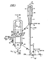
- FIG. 1 by way of example, there is shown a riser cracking zone, a catalyst disengaging and stripping zone adjacent to a two stage catalyst regeneration arrangement stacked one above the other so that flue gas products of the bottom regeneration section can pass upwardly into the bottom portion of a dense fluid bed of catalyst being regenerated in the upper regeneration section.
- a reduced crude is charged by conduit 1 in admixture with one or more of steam naphtha and water, as a diluent material, temperature adjustment material, velocity providing material feed partial pressure reducing material and a combination thereof to assure intimate rapid atomized and vaporized contact of the reduced crude with charged finely divided fluidizable catalyst particles to provide an upwardly flowing suspension at a temperature of at least about 510°C (950°F) and sufficiently elevated to provide a riser outlet temperature in the range of 510°C to 566°C (950°F to 1050°F).
- the upwardly flowing suspension in riser 4 is at a velocity to provide a hydrocarbon residence time within the range of 0.5 to 4 seconds and more usually in the range of 1 to 2 seconds.
- Short residence time may also be provided by charging the reduced crude through inlet means above the riser bottom as by inlet 2 and 7 shown in the presence of suitable diluent material.
- Steam, naphtha or other light hydrocarbons may initially fluidize the catalyst charged to the riser bottom before contact with reduced crude charge by either conduit 2 or 7.
- the suspension following traverse of the riser is separated so that vaporous materials pass through cyclones for removal by conduit 12 and separation in downstream equipment not shown. Separated catalyst particles are collected in an annular stripping zone 14 for countercurrent contact with stripping gas such as steam introduced by conduit 16.
- Catalyst bed 22 comprises the first stage of regeneration in accordance with the processing concepts of this invention. That is, regeneration gas such as air introduced by conduit 24 is mixed with steam introduced by conduit 25 and the mixed gasiform material, predominantly steam at a temperature in the range of 143°C to 238°C (290°F to 460°F) is charged to plenum chamber 26 and thence by distributor arms 27 to a bottom portion of bed 22 for admixture with flue gases obtained as provided below and charged through openings 29. That is, separator baffle means 28 is provided with a plurality of small openings represented by 29 for passage of flue gases therethrough and obtained from the second stage of catalyst regeneration discussed below.
- regeneration gas such as air introduced by conduit 24 is mixed with steam introduced by conduit 25 and the mixed gasiform material, predominantly steam at a temperature in the range of 143°C to 238°C (290°F to 460°F) is charged to plenum chamber 26 and thence by distributor arms 27 to a bottom portion of bed 22 for admixture with flue gases obtained
- baffle 28 is now porous and the flue gases of the second stage regeneration comprising bed 34 are caused to flow into the plenum 26 for admixture with steam prior to entering bed 22 by distributor arms 27.
- flue gases from bed 34 may be passed through external cyclones for removal of catalyst fines returned to bed 34 before passing the flue gases freed of catalyst in admixture with steam to a bottom portion of bed 22.
- the catalyst in dense fluid bed 22 is partially regenerated with oxygen containing gases furnished by the flue gases obtained from the lower bed 34 and being enriched with an air-steam mixture added by gas distributor arms 27 connected to plenum 27. Partial regeneration of the catalyst in bed 22 is accomplished under steam reforming conditions at temperatures within the range of 677°C to 815°C (1250°F to 1500°F). Flue gas products of regeneration pass through cyclone separator means 30 before being withdrawn by conduit 32 for use as desired.
- the partially regenerated catalyst in bed 22 is passed to suitable withdrawal wells communicating with standpipes 36 and 40. All or a portion of the catalyst may be passed by either one or both of standpipes 36 and 40 to catalyst bed 40 in the lower regenerator section. Heating or cooling of the catalyst in standpipe 36 may be accomplished in zone 38 as desired.
- complete regeneration of the catalyst to provide a residual carbon content less than 0.1 wt% and preferably no more than 0.05 wt% is accomplished with an oxygen containing regeneration gas such as air, air modified with C02, C02 modified with oxygen and a combination thereof as required to effect removal of residual carbonaceous material without exceeding a temperature of 815°C (1500°F) and preferably without exceeding a temperature of 760°C (1400°F).
- an oxygen containing regeneration gas such as air, air modified with C02, C02 modified with oxygen and a combination thereof as required to effect removal of residual carbonaceous material without exceeding a temperature of 815°C (1500°F) and preferably without exceeding a temperature of 760°C (1400°F).
- the transfer of catalyst from upper bed 22 to lower bed 34 may also be accomplished by one or more internal standpipes rather than by the external standpipes shown.
- the catalyst regenerated to a desired low level of residual carbon by the combination operation above discussed and at a desired elevated temperature is passed from catalyst bed 34 by standpipe 44 to a lower portion of riser 4 for re-use in the system as above described.
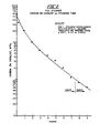
- FIG. 2 a graph directed to presenting data directed to carbon removal with steam from a GRZ-1 cracking catalyst (commercially available catalyst from W. R. Grace & Co - Davidson Chemical Division) which had been coke with Arabian Light Reduced Crude.
- the graph shows that the reaction of steam to remove coke or carbonaceous material is relatively just for significant amounts of coke removal within a time span commensurate with that obtainable in a dense fluid catalyst bed regeneration operation.
- a catalyst comprising about 5.8 wt% carbon on catalyst is reduced to a residual carbon level of about 1.0 wt% when contacted with 787°C (1450°F) steam for 2 hours.
- coke removal is achievable with steam at temperatures of about 760°C (1400°F) to form CO and hydrogen which are combustible with added oxygen to generate needed endothermic heat.
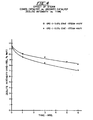
- Figures 3 and 4 show the effect of 787°C (1450°F) steam on a coked and uncoked GRZ-1 catalyst with respect to surface area and zeolite intensity.
- Zeolite intensity is identified with the active zeolite component or the catalyst, the greater the intensity, the more of the active crystalline zeolite component.
- the graphical data of Figures 3 and 4 show that steaming of the uncoked catalyst gave a much larger drop in surface area and zeolite intensity then obtained when contacting a coked catalyst with high temperature steam.
- the coke on the catalyst guards the deactivation of the catalyst against high temperature steam. This finding is used to advantage in pursuit of the concepts of this invention which is directed to reducing the temperature of regeneration of catalysts used in reduced crude cracking.
- Catalyst so used are known to accumulate large amounts of carbonaceous material attributable in substantial measure to the Conradson carbon level of the feed being processed and such high levels of deposited carbonaceous materials are instrumental in causing high temperatures to be encountered by burning removal thereof with oxygen containing gas such as air in the absence of extreme caution, heat dissipation and restrict temperature sequential burning in a plurality' of regeneration zones, all of which techniques are less than desirable.
- the regeneration combination of this invention is not only a unique approach to the removal of relatively large amounts of carbonaceous deposits but so also is the amount of carbonaceous material to be removed by burning with oxygen containing gas sufficiently reduced to permit maintaining desired temperature restrictions below 760°C (1400 0 F) and more preferably at the lowest temperature conditions promoting extended catalyst life and usage.
- oxygen containing gas sufficiently reduced to permit maintaining desired temperature restrictions below 760°C (1400 0 F) and more preferably at the lowest temperature conditions promoting extended catalyst life and usage.
- the regeneration concept of sequence of performance permits the processing of higher Conradson carbon feeds than previously considered possible at relatively low temperatures particularly suitable for achieving desired hydrocarbon conversion results.
Landscapes
- Chemical & Material Sciences (AREA)
- Oil, Petroleum & Natural Gas (AREA)
- Engineering & Computer Science (AREA)
- Chemical Kinetics & Catalysis (AREA)
- General Chemical & Material Sciences (AREA)
- Organic Chemistry (AREA)
- Crystallography & Structural Chemistry (AREA)
- Catalysts (AREA)
- Production Of Liquid Hydrocarbon Mixture For Refining Petroleum (AREA)
Applications Claiming Priority (2)
| Application Number | Priority Date | Filing Date | Title |
|---|---|---|---|
| US36986082A | 1982-04-19 | 1982-04-19 | |
| US369860 | 1982-04-19 |
Publications (2)
| Publication Number | Publication Date |
|---|---|
| EP0092065A1 true EP0092065A1 (de) | 1983-10-26 |
| EP0092065B1 EP0092065B1 (de) | 1986-07-23 |
Family
ID=23457219
Family Applications (1)
| Application Number | Title | Priority Date | Filing Date |
|---|---|---|---|
| EP19830102928 Expired EP0092065B1 (de) | 1982-04-19 | 1983-03-24 | Regeneration eines Katalysators, der bei der Konversion carbo-metallischer Rückstandsöle verwendet worden ist |
Country Status (3)
| Country | Link |
|---|---|
| EP (1) | EP0092065B1 (de) |
| CA (1) | CA1183826A (de) |
| DE (1) | DE3364626D1 (de) |
Cited By (15)
| Publication number | Priority date | Publication date | Assignee | Title |
|---|---|---|---|---|
| EP0152845A1 (de) * | 1984-02-08 | 1985-08-28 | Air Products And Chemicals, Inc. | Methode zur Kontrolle der Temperatur und Fliessgeschwindigkeit eines FCC-Regenerators mittels Carbondioxids |
| EP0323784A1 (de) * | 1988-01-08 | 1989-07-12 | Institut Français du Pétrole | Anwendung eines einen Zeoliten aus der Erionitfamilie enthaltenden Katalysators in einem Krackverfahren, das zumindest eine Regenerationszone enthält |
| EP0332536A1 (de) * | 1988-03-09 | 1989-09-13 | Total Raffinage Distribution S.A. | Verfahren und Vorrichtung zum Regenerieren eines Katalysators in einem Fliessbett |
| FR2628342A1 (fr) * | 1988-03-09 | 1989-09-15 | Total France | Procede et dispositif de regeneration en lit fluidise d'un catalyseur |
| FR2705142A1 (fr) * | 1993-05-10 | 1994-11-18 | Inst Francais Du Petrole | Procédé de régulation du niveau thermique d'un solide dans un échangeur de chaleur présentant des nappes cylindriques de tubes. |
| EP1241154A2 (de) * | 2001-03-17 | 2002-09-18 | Linde Aktiengesellschaft | Verfahren zur Gewinnung von Kohlenwasserstoffprodukten durch thermische Dampfspaltung und nachfolgende katalytische Behandlung |
| DE10209563A1 (de) * | 2002-03-04 | 2003-09-25 | Denise Kirsch | Schmuckring |
| WO2007149922A1 (en) * | 2006-06-22 | 2007-12-27 | Shell Oil Company | Systems and methods for producing a total product with inorganic salt recovery |
| EP2072606A1 (de) * | 2007-12-21 | 2009-06-24 | BP Corporation North America Inc. | System und Verfahren zum Regenerieren eines Katalysators in einer Fluid-Catalytic-Cracking-Einheit |
| US7699975B2 (en) | 2007-12-21 | 2010-04-20 | Uop Llc | Method and system of heating a fluid catalytic cracking unit for overall CO2 reduction |
| US7699974B2 (en) | 2007-12-21 | 2010-04-20 | Uop Llc | Method and system of heating a fluid catalytic cracking unit having a regenerator and a reactor |
| US7767075B2 (en) | 2007-12-21 | 2010-08-03 | Uop Llc | System and method of producing heat in a fluid catalytic cracking unit |
| US7811446B2 (en) | 2007-12-21 | 2010-10-12 | Uop Llc | Method of recovering energy from a fluid catalytic cracking unit for overall carbon dioxide reduction |
| US20100298117A1 (en) * | 2007-11-16 | 2010-11-25 | Doron Levin | Catalyst Regeneration Process |
| US7935245B2 (en) | 2007-12-21 | 2011-05-03 | Uop Llc | System and method of increasing synthesis gas yield in a fluid catalytic cracking unit |
Citations (6)
| Publication number | Priority date | Publication date | Assignee | Title |
|---|---|---|---|---|
| US4056486A (en) * | 1976-05-07 | 1977-11-01 | Texaco Inc. | Fluidized catalytic cracking regeneration process |
| US4062759A (en) * | 1976-05-07 | 1977-12-13 | Texaco Inc. | Fluidized catalytic cracking regeneration process |
| GB2001545A (en) * | 1977-07-28 | 1979-02-07 | Ici Ltd | Hydrocarbon processing |
| GB1569467A (en) * | 1977-11-09 | 1980-06-18 | Texaco Development Corp | Fluidized catalytic cracking regeneration process |
| US4274942A (en) * | 1979-04-04 | 1981-06-23 | Engelhard Minerals & Chemicals Corporation | Control of emissions in FCC regenerator flue gas |
| US4336160A (en) * | 1980-07-15 | 1982-06-22 | Dean Robert R | Method and apparatus for cracking residual oils |
-
1983
- 1983-03-24 DE DE8383102928T patent/DE3364626D1/de not_active Expired
- 1983-03-24 EP EP19830102928 patent/EP0092065B1/de not_active Expired
- 1983-03-29 CA CA000424732A patent/CA1183826A/en not_active Expired
Patent Citations (6)
| Publication number | Priority date | Publication date | Assignee | Title |
|---|---|---|---|---|
| US4056486A (en) * | 1976-05-07 | 1977-11-01 | Texaco Inc. | Fluidized catalytic cracking regeneration process |
| US4062759A (en) * | 1976-05-07 | 1977-12-13 | Texaco Inc. | Fluidized catalytic cracking regeneration process |
| GB2001545A (en) * | 1977-07-28 | 1979-02-07 | Ici Ltd | Hydrocarbon processing |
| GB1569467A (en) * | 1977-11-09 | 1980-06-18 | Texaco Development Corp | Fluidized catalytic cracking regeneration process |
| US4274942A (en) * | 1979-04-04 | 1981-06-23 | Engelhard Minerals & Chemicals Corporation | Control of emissions in FCC regenerator flue gas |
| US4336160A (en) * | 1980-07-15 | 1982-06-22 | Dean Robert R | Method and apparatus for cracking residual oils |
Cited By (23)
| Publication number | Priority date | Publication date | Assignee | Title |
|---|---|---|---|---|
| EP0152845A1 (de) * | 1984-02-08 | 1985-08-28 | Air Products And Chemicals, Inc. | Methode zur Kontrolle der Temperatur und Fliessgeschwindigkeit eines FCC-Regenerators mittels Carbondioxids |
| EP0323784A1 (de) * | 1988-01-08 | 1989-07-12 | Institut Français du Pétrole | Anwendung eines einen Zeoliten aus der Erionitfamilie enthaltenden Katalysators in einem Krackverfahren, das zumindest eine Regenerationszone enthält |
| FR2625748A1 (fr) * | 1988-01-08 | 1989-07-13 | Inst Francais Du Petrole | Utilisation d'un catalyseur contenant une zeolithe de la famille erionite dans un procede de craquage comportant au moins une zone de regeneration |
| EP0332536A1 (de) * | 1988-03-09 | 1989-09-13 | Total Raffinage Distribution S.A. | Verfahren und Vorrichtung zum Regenerieren eines Katalysators in einem Fliessbett |
| FR2628342A1 (fr) * | 1988-03-09 | 1989-09-15 | Total France | Procede et dispositif de regeneration en lit fluidise d'un catalyseur |
| US4965232A (en) * | 1988-03-09 | 1990-10-23 | Compagnie De Raffinage Et De Distribution Total France | Process for fluidized-bed catalyst regeneration |
| FR2705142A1 (fr) * | 1993-05-10 | 1994-11-18 | Inst Francais Du Petrole | Procédé de régulation du niveau thermique d'un solide dans un échangeur de chaleur présentant des nappes cylindriques de tubes. |
| WO1994026845A1 (fr) * | 1993-05-10 | 1994-11-24 | Institut Français Du Petrole | Procede de regulation du niveau thermique d'un solide dans un echangeur de chaleur presentant des nappes cylindriques de tubes |
| US5773379A (en) * | 1993-05-10 | 1998-06-30 | Institut Francais Du Petrole | Thermal regulation process for a solid in a heat exchanger using cylindrical tube surfaces |
| EP1241154A3 (de) * | 2001-03-17 | 2003-08-13 | Linde Aktiengesellschaft | Verfahren zur Gewinnung von Kohlenwasserstoffprodukten durch thermische Dampfspaltung und nachfolgende katalytische Behandlung |
| EP1241154A2 (de) * | 2001-03-17 | 2002-09-18 | Linde Aktiengesellschaft | Verfahren zur Gewinnung von Kohlenwasserstoffprodukten durch thermische Dampfspaltung und nachfolgende katalytische Behandlung |
| DE10209563A1 (de) * | 2002-03-04 | 2003-09-25 | Denise Kirsch | Schmuckring |
| WO2007149922A1 (en) * | 2006-06-22 | 2007-12-27 | Shell Oil Company | Systems and methods for producing a total product with inorganic salt recovery |
| US8822363B2 (en) * | 2007-11-16 | 2014-09-02 | Exxonmobil Chemical Patents Inc. | Catalyst regeneration process |
| US20100298117A1 (en) * | 2007-11-16 | 2010-11-25 | Doron Levin | Catalyst Regeneration Process |
| US7767075B2 (en) | 2007-12-21 | 2010-08-03 | Uop Llc | System and method of producing heat in a fluid catalytic cracking unit |
| US7699974B2 (en) | 2007-12-21 | 2010-04-20 | Uop Llc | Method and system of heating a fluid catalytic cracking unit having a regenerator and a reactor |
| US7811446B2 (en) | 2007-12-21 | 2010-10-12 | Uop Llc | Method of recovering energy from a fluid catalytic cracking unit for overall carbon dioxide reduction |
| US7699975B2 (en) | 2007-12-21 | 2010-04-20 | Uop Llc | Method and system of heating a fluid catalytic cracking unit for overall CO2 reduction |
| US7921631B2 (en) | 2007-12-21 | 2011-04-12 | Uop Llc | Method of recovering energy from a fluid catalytic cracking unit for overall carbon dioxide reduction |
| US7932204B2 (en) | 2007-12-21 | 2011-04-26 | Uop Llc | Method of regenerating catalyst in a fluidized catalytic cracking unit |
| US7935245B2 (en) | 2007-12-21 | 2011-05-03 | Uop Llc | System and method of increasing synthesis gas yield in a fluid catalytic cracking unit |
| EP2072606A1 (de) * | 2007-12-21 | 2009-06-24 | BP Corporation North America Inc. | System und Verfahren zum Regenerieren eines Katalysators in einer Fluid-Catalytic-Cracking-Einheit |
Also Published As
| Publication number | Publication date |
|---|---|
| DE3364626D1 (en) | 1986-08-28 |
| EP0092065B1 (de) | 1986-07-23 |
| CA1183826A (en) | 1985-03-12 |
Similar Documents
| Publication | Publication Date | Title |
|---|---|---|
| EP0106052B1 (de) | Entmetallisierung und Entkarbonisierung schwerer Rückstandsöl-Einsatzprodukte | |
| US4436613A (en) | Two stage catalytic cracking process | |
| CA1156591A (en) | Method for two stage catalyst regeneration | |
| US4388218A (en) | Regeneration of cracking catalyst in two successive zones | |
| EP0171460B1 (de) | Verfahren zur katalytischen Spaltung von Residualölen mit Trockengas als Auftriebgas in einem Steigrohrreaktor | |
| US4875994A (en) | Process and apparatus for catalytic cracking of residual oils | |
| EP2161322B1 (de) | Rückgewinnung des Katalysators aus einem leichte Olefine enthaltenden FCC Abgasstrom | |
| US4116814A (en) | Method and system for effecting catalytic cracking of high boiling hydrocarbons with fluid conversion catalysts | |
| US4786400A (en) | Method and apparatus for catalytically converting fractions of crude oil boiling above gasoline | |
| US4090948A (en) | Catalytic cracking process | |
| US5589139A (en) | Downflow FCC reaction arrangement with upflow regeneration | |
| CA1183826A (en) | Regeneration of catalyst used in the conversion of carbo-metallic containing residual oils | |
| US4584090A (en) | Method and apparatus for catalytically converting fractions of crude oil boiling above gasoline | |
| EP0074501B1 (de) | Verfahren und Katalysator für die Umwandlung von Koksvorläufer und Schwermetalle enthaltenden Ölen | |
| US3926843A (en) | Fcc ' 'multi-stage regeneration procedure | |
| JPS61501454A (ja) | 貴重な液体生成物が高収率で得られる重質炭化水素のクラツキング | |
| US4457833A (en) | Process and catalyst for the conversion of carbo-metallic containing oils | |
| EP0134924B1 (de) | Zugabe von Wasser zur Regenerationsluft | |
| US4894141A (en) | Combination process for upgrading residual oils | |
| US5362380A (en) | Fluid catalytic cracking process yielding hydrogen | |
| US4428822A (en) | Fluid catalytic cracking | |
| US4915820A (en) | Removal of coke and metals from carbo-metallic oils | |
| EP0092059A1 (de) | Regeneration eines Katalysators, der bei der Konversion carbo-metallischer Rückstandsöle verwendet worden ist | |
| US8840846B2 (en) | Method and apparatus for catalytic cracking | |
| US20040140246A1 (en) | Process for upgrading fcc product with additional reactor |
Legal Events
| Date | Code | Title | Description |
|---|---|---|---|
| PUAI | Public reference made under article 153(3) epc to a published international application that has entered the european phase |
Free format text: ORIGINAL CODE: 0009012 |
|
| AK | Designated contracting states |
Designated state(s): AT BE DE FR GB IT NL SE |
|
| 17P | Request for examination filed |
Effective date: 19840425 |
|
| GRAA | (expected) grant |
Free format text: ORIGINAL CODE: 0009210 |
|
| AK | Designated contracting states |
Kind code of ref document: B1 Designated state(s): DE FR GB NL |
|
| REF | Corresponds to: |
Ref document number: 3364626 Country of ref document: DE Date of ref document: 19860828 |
|
| ET | Fr: translation filed | ||
| PLBE | No opposition filed within time limit |
Free format text: ORIGINAL CODE: 0009261 |
|
| STAA | Information on the status of an ep patent application or granted ep patent |
Free format text: STATUS: NO OPPOSITION FILED WITHIN TIME LIMIT |
|
| 26N | No opposition filed | ||
| PG25 | Lapsed in a contracting state [announced via postgrant information from national office to epo] |
Ref country code: DE Effective date: 19881201 |
|
| PGFP | Annual fee paid to national office [announced via postgrant information from national office to epo] |
Ref country code: FR Payment date: 19901218 Year of fee payment: 9 |
|
| PGFP | Annual fee paid to national office [announced via postgrant information from national office to epo] |
Ref country code: GB Payment date: 19901224 Year of fee payment: 9 |
|
| PGFP | Annual fee paid to national office [announced via postgrant information from national office to epo] |
Ref country code: NL Payment date: 19910331 Year of fee payment: 9 |
|
| PG25 | Lapsed in a contracting state [announced via postgrant information from national office to epo] |
Ref country code: GB Effective date: 19920324 |
|
| PG25 | Lapsed in a contracting state [announced via postgrant information from national office to epo] |
Ref country code: NL Effective date: 19921001 |
|
| NLV4 | Nl: lapsed or anulled due to non-payment of the annual fee | ||
| GBPC | Gb: european patent ceased through non-payment of renewal fee | ||
| PG25 | Lapsed in a contracting state [announced via postgrant information from national office to epo] |
Ref country code: FR Effective date: 19921130 |
|
| REG | Reference to a national code |
Ref country code: FR Ref legal event code: ST |