EP0092007B1 - Wellendichtung - Google Patents
Wellendichtung Download PDFInfo
- Publication number
- EP0092007B1 EP0092007B1 EP19820305902 EP82305902A EP0092007B1 EP 0092007 B1 EP0092007 B1 EP 0092007B1 EP 19820305902 EP19820305902 EP 19820305902 EP 82305902 A EP82305902 A EP 82305902A EP 0092007 B1 EP0092007 B1 EP 0092007B1
- Authority
- EP
- European Patent Office
- Prior art keywords
- shaft
- sealing arrangement
- valve element
- wall
- arrangement according
- Prior art date
- Legal status (The legal status is an assumption and is not a legal conclusion. Google has not performed a legal analysis and makes no representation as to the accuracy of the status listed.)
- Expired
Links
- 238000007789 sealing Methods 0.000 claims description 34
- 239000012530 fluid Substances 0.000 claims description 19
- 238000005192 partition Methods 0.000 claims description 7
- 238000004891 communication Methods 0.000 claims description 4
- 239000013013 elastic material Substances 0.000 claims 1
- 239000010687 lubricating oil Substances 0.000 description 5
- 238000002485 combustion reaction Methods 0.000 description 4
- 239000000463 material Substances 0.000 description 4
- 239000003921 oil Substances 0.000 description 3
- 238000005299 abrasion Methods 0.000 description 2
- WYTGDNHDOZPMIW-RCBQFDQVSA-N alstonine Natural products C1=CC2=C3C=CC=CC3=NC2=C2N1C[C@H]1[C@H](C)OC=C(C(=O)OC)[C@H]1C2 WYTGDNHDOZPMIW-RCBQFDQVSA-N 0.000 description 2
- 210000004907 gland Anatomy 0.000 description 2
- 238000003466 welding Methods 0.000 description 2
- 229910000639 Spring steel Inorganic materials 0.000 description 1
- 230000007423 decrease Effects 0.000 description 1
- 239000000446 fuel Substances 0.000 description 1
- 238000000034 method Methods 0.000 description 1
- 238000005086 pumping Methods 0.000 description 1
- 239000012858 resilient material Substances 0.000 description 1
- 230000035945 sensitivity Effects 0.000 description 1
- 239000007787 solid Substances 0.000 description 1
- 238000011144 upstream manufacturing Methods 0.000 description 1
Images
Classifications
-
- F—MECHANICAL ENGINEERING; LIGHTING; HEATING; WEAPONS; BLASTING
- F16—ENGINEERING ELEMENTS AND UNITS; GENERAL MEASURES FOR PRODUCING AND MAINTAINING EFFECTIVE FUNCTIONING OF MACHINES OR INSTALLATIONS; THERMAL INSULATION IN GENERAL
- F16J—PISTONS; CYLINDERS; SEALINGS
- F16J15/00—Sealings
- F16J15/16—Sealings between relatively-moving surfaces
- F16J15/40—Sealings between relatively-moving surfaces by means of fluid
-
- F—MECHANICAL ENGINEERING; LIGHTING; HEATING; WEAPONS; BLASTING
- F01—MACHINES OR ENGINES IN GENERAL; ENGINE PLANTS IN GENERAL; STEAM ENGINES
- F01D—NON-POSITIVE DISPLACEMENT MACHINES OR ENGINES, e.g. STEAM TURBINES
- F01D11/00—Preventing or minimising internal leakage of working-fluid, e.g. between stages
- F01D11/02—Preventing or minimising internal leakage of working-fluid, e.g. between stages by non-contact sealings, e.g. of labyrinth type
- F01D11/04—Preventing or minimising internal leakage of working-fluid, e.g. between stages by non-contact sealings, e.g. of labyrinth type using sealing fluid, e.g. steam
Definitions
- the present invention relates to a shaft seal for a rotary machine and to a rotary machine incorporating a shaft sealing arrangement. More particularly, this invention relates to a sealing arrangement of the so-called knife edge type which is frequently utilized in high-speed rotary machinery to prevent the leakage of a fluid along a shaft where the shaft penetrates a housing of the machine.
- Alberic's US Patent Specification No. 4114058 teaches the idea of a fluid seal for a rotating shaft, the operation of which seal is different at different shaft speeds.
- GEC's British Patent Specification No. 9282085 discloses a fluid flow seal in which fluid pumped by the rotating components is used to prevent leakage along a gland seal.
- the present invention arises from the discovery that with a conventional seal using fluid pressurised by pumping of the rotary components, as for example taught by GEC, the seal may not be adequate at lower speeds because of the drop in sealing fluid pressure.
- a shaft sealing arrangement for a rotary machine having a housing with an opening through which passes a rotatable shaft, co-operates with the said housing and the said shaft so as substantially to prevent leakage of a first fluid through the said opening by means of a flow of pressurised sealing fluid through a flow path, and a centrifugally responsive valve means rotating with the shaft and having a flow restricting orifice, is operable at certain rotational speeds of the machine to introduce the orifice into the flow path to restrict the rate of flow of the sealing fluid.
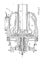
- Figure 1 illustrates a turbine machine 20 having a housing 22 comprising a first part 24 and a second part 26 which are connected by a plurality of circumferentially spaced struts 28 (only two of which are visible in Figure 1).
- the two parts 24 and 26 of the housing cooperate to define an annular air inlet 30 leading first radially inwardly and leading then generally axially to a centrifugal compressor wheel 32.
- the compressor wheel 32 and a radial inflow turbine wheel 34 are carried by a shaft assembly.
- a pair of bearings 38 and 40 carry the shaft assembly and are in turn received in a bore 42 formed in the first housing part 24.
- an annular discharge chamber 44 formed within the second part 26 of the housing.
- This chamber 44 communicates with a combustor 46 (only a portion of which is visible in Figure 1) which receives pressurized air from the chamber 44 and fuel via a conduit 48 to maintain combustion producing a supply of hot pressurized combustion products.
- An annular chamber 50 within the chamber 44 receives the combustion products from the combustor 46 and directs them to the turbine wheel 34.
- An inner, circumferentially extending wall 52 of the part 26 of the housing defines an exhaust duct 54 leading from the turbine wheel 34 to the atmosphere.
- the turbine wheel 34 drives the shaft assembly, which in turn drives the compressor wheel 32.
- the shaft assembly has a shaft 36 with a splined end portion 56 for connection with a power-absorbing device (not shown).
- the compressor wheel 32 is formed at a radially inner location with an axially extending annular recess 58.
- the part 24 of the housing includes a generally cylindrical or tubular part 60 which extends axially into the recess 58.
- a sleeve-like seal member 62 is carried by a generally cylindrical radially innermost central portion 64 of the compressor wheel 32.
- the sleeve-like seal member 62 forms part of the shaft assembly and the radially outer surface 66 of this sleeve member 62 is spaced radially inwardly from the tubular part of the casing part 24 and has several circumferentially extending and axially spaced knife-edge seal elements 70Ato 70F extending radially outwardly towards a tubular member 68 of abrasion resistant material carried on the radially inner surface of the tubular part 60.
- the knife-edge seal elements 70A to 70F and the tubular member 68 together define a series of adjacent but axially separated annular chambers 72A to 72E, separated that is from each other by the knife-edge seal elements 70A to 70F, but in fluid communication with one another because of a slight radial clearance between the knife-edge elements 70A to 70F and the tubular member 68.
- the compressor wheel 32 and the turbine wheel 34 are axially spaced from one another and each defines an annular shoulder 74 or 76 respectively, which face one another.
- An annular seal member 78 is located by the shoulders 74, 76, this seal having two radially outwardly projecting annular ribs constituting knife-edge seals.
- the housing 22 also includes an annular partition member 80 extending radially inwardly between the compressor wheel 32 and the turbine wheel 34 and serving to prevent the flow of pressurized air from the compressor 32 to the turbine 34 except by way of the combustor 46.
- the partition member 80 has an enlarged radially inner rim 82 to which an annular element 84 of abrasion resistant material is secured, which sealingly cooperates with the seal member 78.
- the seal member 78 In the lower part of the seal member 78 (as viewed in Figure 2) it has a notch 88 opening from the side of partition member 80 facing the compressor wheel 32 and leading to an annular chamber 90 between the turbine wheel 34 and the compressorwheel 32 radially inwardly of the shoulders 74,76.
- the notch 88 communicates with the chamber 44, into which the compressor 32 discharges, via an annular clearance space 92 between a back face 94 of the compressor wheel 32 and the partition member 80.
- a radially inner annular passage 96 leads from the chamber 90 to an annular chamber 98 defined between the inner surface of the central portion 64 of the compressor wheel 32 and a circumferential groove 100 on the shaft 36.
- a radially extending passage 102 leads from the chamber 98 into an annular chamber 104 defined between an annular recess 106 in the radially inner face of the seal member 62, and an opposed radially-outer face of the central portion 64.
- a radially extending passage 108 in the seal member 62 itself puts the chamber 104 into communication with the central chamber 72C of the set of chambers 72A to 72E separated by the knife blade seals 70A to 70E.
- a curved valve element 110 is disposed within the annular chamber 104.
- the valve element 110 comprises a length of resilient strip material, such as spring steel, one end portion 112 of which is bent to extend radially inwardly towards the shaft 36.
- the valve element 110 is secured to the sealing member 62 adjacent the end portion 112, such as by spot welding.
- the normal shape of the valve element 110 when unstressed, is the spiral shape shown in Figure 3, in which the end 114 of the strip is resiliently biased against the rests upon the bent end portion 112. Consequently, the remaining portion 116 of the valve element 110, intermediate the two ends, is spaced away from the seal member 62 so that the passage 108 is substantially unobstructed.
- the pressurized air reaches the chamber72C through the space 92, the notch 88 in the annular seal 78, the chamber 90,the passage 96, the chamber 98, the passage 102, the chamber 104, the metering orifice 118, and finally the radial passage 108 in the seal element 62.
- the pressurized air flows in both axial directions via the clearances between the knife edge seal elements 70A to 70E and the sleeve 68.
- the pressurized air flowing to the right (as seen in Figure 2) from the chamber 72C escapes eventually into the low pressure area in the inlet 30 upstream of the compressor wheel 32.
- pressurized air flowing to the left (as seen in Figure 2) from the chamber 72C flows into a chamber 120 within the bore 42 in the housing part 24.
- the chamber 120 is supplied with a flow of lubricating oil during operation of the machine 20 to cool and lubricate the bearings 38 and 40.
- the pressurized air flowing from the chamber 72C past the knife edge elements 70A to 70C and into the chamber 120 prevents the lubricating oil in the chamber 120 from being drawn into the low pressure area of the inlet 30.
- the lubricating oil and air are scavenged by means not shown to an oil sump (also not shown) where the air is separated from the oil and vented.
- the size of the orifice 118 is selected to allow an appropriate and predetermined air flow rate from the compressor wheel 32 to the chamber 72C at normal design speed operation of the machine 20. Thus, leakage of lubricating oil into the inlet 30 is prevented while minimizing the amount of pressurized air bled from the compressor wheel for this purpose.
- the compressor wheel 32 maintains a low pressure at the inlet 30, even though it does not develop its maximum design pressure because it is operating below its design speed.
- the small orifice 118 if it were permanently operative, would only allow an insufficient air flow from the compressor wheel 32 to chamber 72C so that leakage of lubricating oil into the inlet 30 would be possible.
- the valve element 110 the weight and resilience of which are selected so that the valve moves from its position illustrated in Figure 4to that illustrated in Figure 3 as the machine slows down.
- the full flow area of the passage 108 is made available for air flow into the chamber 72C.
- valve element remains in the position illustrated in Figure 3, to allow air flow through the full area of passage 108 during the initial low-speed operation of the compressor wheel 32 as the machine runs up to its design speed. At a certain speed, the resilience of the valve element is overcome by centrifugal force and the valve element then moves to the position illustrated in Figure 4 to prevent an excessively high air flow to the chamber 72C.
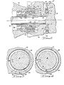
- FIG. 5 and 5A An alternative embodiment of the invention is illustrated in Figures 5 and 5A, wherein features analogous to those described above in relation to Figures 1 to 4 are identified with the numerals used previously but increased by 200.
- a curved valve element 310 is disposed within a chamber 304 from which leads a radial passage 308.
- the valve element 310 comprises a strip of resilient material, a developed view of which is shown in Figure 5A, which is curled into an approximately circular shape, as seen in viewing Figure 5, and secured to a seal member 262 at two locations 122, such as by spot welding.
- the valve element 310 has a central portion 124 and a pair of opposite end portions 126. The end portions 126 define the securing locations 122.
- a pair of serpentine-shape resiliently elastic sections 128 connect the central portion 124 to the end portions 126 to allow for relative movement therebetween.
- the valve element 310 in its unstressed position is disposed with its central portion 124 spaced from the passage 308 so that the full area of the passage 308 is available for the flow of pressurized air.
- the centrifugal force overcomes the resilience of the serpentine sections 128 so that the central portion 124 is urged radially outwardly into engagement with the seal member 262 (as is illustrated in broken outline in Figure 5).
- the central portion 124 has a flow limiting metering orifice 318 which is in alignment with the passage 308 when the valve element 310 is in its radially outward position, whereby to restrict the flow of pressurized air through the passage 308 when the speed of the shaft assembly 336 is above the said certain predetermined speed.
- the serpentine resiliently elastic sections 128 pull the central portion 124 away from the passage 308 to allow an increased air flow at the lower shaft speeds.
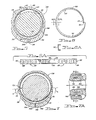
- FIGS 6 and 6A illustrate another embodiment of the invention in which a valve element 510 has a similar shape to the corresponding valve element in the embodiment of Figures 1-4.
- the valve element 510 is channel or U-shape in cross section as illustrated in Figure 6A throughout most of its length.
- the valve element 510 operates in the same manner as the valve element 110 of Figures 1-4.
- the valve element 510 offers a higher ratio of spring rate to mass so that the valve element 510 moves between its two alternative positions at a higher rotational speed than the valve element in the embodiment of Figures 1 to 4.
- the configuration of valve element 510 is particularly appropriate for use in machines having a very high design operating speed.
- FIGs 7 and 7A illustrate a further embodiment of the invention in which a valve element 710 has a shape similar to that of the valve element 110 in the.embodiment of Figures 1-4 and to element 510 of Figures 6 and 6A.
- the valve element 710 operates slightly differently from these in order to obtain a high operating speed whilst nevertheless using a flat rather than channel cross-sectional shape for the valve element 710.
- valve element 710 is formed of flat strip material like the element 110 of Figures 1-4, but a portion 130 of the valve element 710 (which is delimited by an arc the ends of which are indicated by the arrows A) in its normal (that is unstressed) shape has a radius of curvature which is larger than the radius of curvature of the recess 706. Consequently, a free end 132 of the valve element 710 contacts the radially inner surface of the seal member 662.
- the portion 130 of the valve element 710 resists the centrifugal force like a simple beam (albeit, a curved simple beam) which is constrained at its right end (as viewed in Figure 7) and slidably supported at its left end (again as viewed in Figure 7).
- valve element 720 shifts to the stressed position illustrated in broken outline in Figure 7, in which position an orifice 718 is in alignment with a passage 708 whereby to restrict the air flow through the passage 708 which below the said predetermined speed is not restricted.
- the valve element 710 moves back to the position illustrated in solid outline in Figure 7 to allow a substantially unrestricted air flow through the passage 708.
Landscapes
- Engineering & Computer Science (AREA)
- General Engineering & Computer Science (AREA)
- Mechanical Engineering (AREA)
- Sealing Using Fluids, Sealing Without Contact, And Removal Of Oil (AREA)
- Structures Of Non-Positive Displacement Pumps (AREA)
- Sealing Of Bearings (AREA)
- Turbine Rotor Nozzle Sealing (AREA)
Claims (13)
Applications Claiming Priority (2)
| Application Number | Priority Date | Filing Date | Title |
|---|---|---|---|
| US35550582A | 1982-03-08 | 1982-03-08 | |
| US355505 | 1982-03-08 |
Publications (2)
| Publication Number | Publication Date |
|---|---|
| EP0092007A1 EP0092007A1 (de) | 1983-10-26 |
| EP0092007B1 true EP0092007B1 (de) | 1987-10-14 |
Family
ID=23397680
Family Applications (1)
| Application Number | Title | Priority Date | Filing Date |
|---|---|---|---|
| EP19820305902 Expired EP0092007B1 (de) | 1982-03-08 | 1982-11-05 | Wellendichtung |
Country Status (4)
| Country | Link |
|---|---|
| EP (1) | EP0092007B1 (de) |
| JP (1) | JPS58152971A (de) |
| CA (1) | CA1203261A (de) |
| DE (1) | DE3277464D1 (de) |
Families Citing this family (1)
| Publication number | Priority date | Publication date | Assignee | Title |
|---|---|---|---|---|
| CN112228224B (zh) * | 2020-10-14 | 2021-04-27 | 上海尚实能源科技有限公司 | 一种燃气轮机发动机自增压封严压力回油轴承腔 |
Family Cites Families (3)
| Publication number | Priority date | Publication date | Assignee | Title |
|---|---|---|---|---|
| DE1215889B (de) * | 1962-02-23 | 1966-05-05 | Homberg K G | Seilschrapper |
| US3133693A (en) * | 1962-05-17 | 1964-05-19 | Gen Electric | Sump seal system |
| US4114058A (en) * | 1976-09-03 | 1978-09-12 | Westinghouse Electric Corp. | Seal arrangement for a discharge chamber for water cooled turbine generator rotor |
-
1982
- 1982-11-01 CA CA000414590A patent/CA1203261A/en not_active Expired
- 1982-11-04 JP JP57192657A patent/JPS58152971A/ja active Granted
- 1982-11-05 DE DE8282305902T patent/DE3277464D1/de not_active Expired
- 1982-11-05 EP EP19820305902 patent/EP0092007B1/de not_active Expired
Also Published As
| Publication number | Publication date |
|---|---|
| JPS58152971A (ja) | 1983-09-10 |
| DE3277464D1 (en) | 1987-11-19 |
| JPS6216355B2 (de) | 1987-04-11 |
| EP0092007A1 (de) | 1983-10-26 |
| CA1203261A (en) | 1986-04-15 |
Similar Documents
| Publication | Publication Date | Title |
|---|---|---|
| US4543038A (en) | Sealing apparatus and method and machinery utilizing same | |
| EP0623768B1 (de) | Labyrinth-Gasdichtung | |
| US2976013A (en) | Turbine construction | |
| US4257617A (en) | Shaft seal assembly | |
| US8919781B2 (en) | Self-adjusting non-contact seal | |
| EP0395825B1 (de) | Lagereinheit für einen Turbolader | |
| CA1138914A (en) | Gas seal bushing | |
| CA1234051A (en) | Anti-weepage valve for rotating seals | |
| US5688105A (en) | Brush seal for turbo-engines | |
| EP1653130A1 (de) | Druckbalancierte Ringdichtung | |
| US2555492A (en) | Pressure fluid seal | |
| JP4524050B2 (ja) | ターボチャージャー | |
| US6142729A (en) | Sealing device for a turbomachine bearing chamber | |
| US7549836B2 (en) | Bearing seal with backup device | |
| EP2913567B1 (de) | Versiegelungsvorrichtung und drehmaschine | |
| EP0006311A1 (de) | Dichtungsanordnung | |
| JPH10281299A (ja) | メカニカルシール装置 | |
| US4865332A (en) | Sealing arrangement between a shaft and a housing of a fluid flow engine | |
| US4606652A (en) | Shaft seal for turbomachinery | |
| CA1173806A (en) | Differential pressure control for gas seal in turbo machinery | |
| GB2091356A (en) | Oil seal device for rotary machines | |
| US2835514A (en) | Rotary shaft seal | |
| EP0115937A1 (de) | Bienenwabenartige Labyrinthdichtung mit Nuten | |
| CA1067945A (en) | Bearing retaining plate | |
| EP0092007B1 (de) | Wellendichtung |
Legal Events
| Date | Code | Title | Description |
|---|---|---|---|
| PUAI | Public reference made under article 153(3) epc to a published international application that has entered the european phase |
Free format text: ORIGINAL CODE: 0009012 |
|
| AK | Designated contracting states |
Designated state(s): DE FR GB |
|
| 17P | Request for examination filed |
Effective date: 19840417 |
|
| GRAA | (expected) grant |
Free format text: ORIGINAL CODE: 0009210 |
|
| AK | Designated contracting states |
Kind code of ref document: B1 Designated state(s): DE FR GB |
|
| REF | Corresponds to: |
Ref document number: 3277464 Country of ref document: DE Date of ref document: 19871119 |
|
| ET | Fr: translation filed | ||
| PLBE | No opposition filed within time limit |
Free format text: ORIGINAL CODE: 0009261 |
|
| STAA | Information on the status of an ep patent application or granted ep patent |
Free format text: STATUS: NO OPPOSITION FILED WITHIN TIME LIMIT |
|
| 26N | No opposition filed | ||
| PGFP | Annual fee paid to national office [announced via postgrant information from national office to epo] |
Ref country code: DE Payment date: 19881230 Year of fee payment: 7 |
|
| PG25 | Lapsed in a contracting state [announced via postgrant information from national office to epo] |
Ref country code: GB Effective date: 19891105 |
|
| GBPC | Gb: european patent ceased through non-payment of renewal fee | ||
| PG25 | Lapsed in a contracting state [announced via postgrant information from national office to epo] |
Ref country code: FR Effective date: 19900731 |
|
| PG25 | Lapsed in a contracting state [announced via postgrant information from national office to epo] |
Ref country code: DE Effective date: 19900801 |
|
| REG | Reference to a national code |
Ref country code: FR Ref legal event code: ST |