EP0091985A1 - Electro power generating device - Google Patents
Electro power generating device Download PDFInfo
- Publication number
- EP0091985A1 EP0091985A1 EP82109072A EP82109072A EP0091985A1 EP 0091985 A1 EP0091985 A1 EP 0091985A1 EP 82109072 A EP82109072 A EP 82109072A EP 82109072 A EP82109072 A EP 82109072A EP 0091985 A1 EP0091985 A1 EP 0091985A1
- Authority
- EP
- European Patent Office
- Prior art keywords
- series
- plates
- generating device
- power generating
- rotatable
- Prior art date
- Legal status (The legal status is an assumption and is not a legal conclusion. Google has not performed a legal analysis and makes no representation as to the accuracy of the status listed.)
- Withdrawn
Links
Images
Classifications
-
- H—ELECTRICITY
- H02—GENERATION; CONVERSION OR DISTRIBUTION OF ELECTRIC POWER
- H02K—DYNAMO-ELECTRIC MACHINES
- H02K7/00—Arrangements for handling mechanical energy structurally associated with dynamo-electric machines, e.g. structural association with mechanical driving motors or auxiliary dynamo-electric machines
- H02K7/18—Structural association of electric generators with mechanical driving motors, e.g. with turbines
- H02K7/1807—Rotary generators
- H02K7/1823—Rotary generators structurally associated with turbines or similar engines
- H02K7/183—Rotary generators structurally associated with turbines or similar engines wherein the turbine is a wind turbine
-
- H—ELECTRICITY
- H02—GENERATION; CONVERSION OR DISTRIBUTION OF ELECTRIC POWER
- H02K—DYNAMO-ELECTRIC MACHINES
- H02K21/00—Synchronous motors having permanent magnets; Synchronous generators having permanent magnets
- H02K21/12—Synchronous motors having permanent magnets; Synchronous generators having permanent magnets with stationary armatures and rotating magnets
- H02K21/24—Synchronous motors having permanent magnets; Synchronous generators having permanent magnets with stationary armatures and rotating magnets with magnets axially facing the armatures, e.g. hub-type cycle dynamos
-
- F—MECHANICAL ENGINEERING; LIGHTING; HEATING; WEAPONS; BLASTING
- F05—INDEXING SCHEMES RELATING TO ENGINES OR PUMPS IN VARIOUS SUBCLASSES OF CLASSES F01-F04
- F05B—INDEXING SCHEME RELATING TO WIND, SPRING, WEIGHT, INERTIA OR LIKE MOTORS, TO MACHINES OR ENGINES FOR LIQUIDS COVERED BY SUBCLASSES F03B, F03D AND F03G
- F05B2240/00—Components
- F05B2240/20—Rotors
- F05B2240/21—Rotors for wind turbines
- F05B2240/211—Rotors for wind turbines with vertical axis
- F05B2240/213—Rotors for wind turbines with vertical axis of the Savonius type
-
- Y—GENERAL TAGGING OF NEW TECHNOLOGICAL DEVELOPMENTS; GENERAL TAGGING OF CROSS-SECTIONAL TECHNOLOGIES SPANNING OVER SEVERAL SECTIONS OF THE IPC; TECHNICAL SUBJECTS COVERED BY FORMER USPC CROSS-REFERENCE ART COLLECTIONS [XRACs] AND DIGESTS
- Y02—TECHNOLOGIES OR APPLICATIONS FOR MITIGATION OR ADAPTATION AGAINST CLIMATE CHANGE
- Y02E—REDUCTION OF GREENHOUSE GAS [GHG] EMISSIONS, RELATED TO ENERGY GENERATION, TRANSMISSION OR DISTRIBUTION
- Y02E10/00—Energy generation through renewable energy sources
- Y02E10/70—Wind energy
- Y02E10/72—Wind turbines with rotation axis in wind direction
Definitions
- This invention generally relates to an electrical power generating device that can easily produce an alternating voltage of 110 to 220 volts.
- a power generating device consisting of a superposed rotatable upper housing and a lower or stationary housing.
- the lower housing is defined with a circular horizontal wall having on its upper surface a series of radially spaced coiled windings.
- the rotatable housing integrally carried on the upper surface of its circular horizontal wall a series of radially disposed wind power arctuated blades uprightly extending therefrom.
- Secured on the lower surface of this upper housing and substantially insulated therein is a circular plate having on its lower surface a series of radially spaced magnets securely held or fixed thereto and in communication with said coiled windings.
- the upper housing is rota.tably secured with the lower housing through an axial shaft centrally disposed therein.
- the present invention which is actually another embodiment or modification of my Philippine Patent No. 13225 now contemplates stationary upper and lower circular closure members having within a series or multi-layer of rotatable plates or disk and stationary plates alternately with said rotatable plates. Said alternate plates are disposed between said upper and lower closure members in superposed and proximately spaced-apart manner.
- Each of said rotatable plates carries a series of magnets radially spaced underneath thereof.
- Each of said stationary plate has a series of coiled windings radially disposed on its upper surface and in communication with said magnets.
- Rotatably secured vertically on the upper surface of said upper closure member is a series of radially disposed wind powered arctuated blades having an axial shaft downwardly extending therefrom. Secured on the extended portion of this shaft is the said series of rotatable horizontal plates.
- an object of the invention is to provide a brushless and friction-less electrical power generating device with a high conversion efficiency that requires less force to operate and consumes no fuel in generating electricity.
- Another object of the invention is to provide a power generating device having a series or multi-layer of rotatable plates each having a series of magnets radially spaced thereto and a series of coiled windings radially disposed on a series of stationary plates, each of said stationary plates being alternately disposed on each of the rotatable plates.
- Still another object of the invention is to provide a power generating device having upper and lower closure members detachably securing said alternate layers rotatable and stationary plates.
- a further object of the invention is to provide an electric power generating device that can be driven by wind power of all forms including chimney or flue draft, steam generated from solar thermal energy engines, solid and liquid biofuels, biogas, flowing water, falling water, sea waves, geothermal energy, draft animals, pedal power or manually operated cranks and levers, and other conventional fuels.
- Still a further object of this invention is to provide an electric power generating device that is simple in structure, light and compact, and economical to manufacture.
- an electrical power generating device generally designated as 10.
- This device essentially comprises circular upper and lower closure members 11 and 12, a multi-layer of magnet-carrying rotatable plates 13 and coiled winding's stationary plates 14 which are alternately disposed with each of said rotatable plates 13 and superposedly fixed between said closure members 11 and 12, and a series of wind-powered rotatable arctuated blades 15 radially disposed vertically on said upper closure members 11 having a downwardly extending axial shaft 16 securing horizontally said layer of rotatable plates 13.
- the axial shaft 16 can also be driven by energy derived from flowing or falling waters, sea waves, steam generated by solar or geothermal energy engines, human and animal energy, solid and liquid biofuels, biogas, and other conventional fuels.
- Each of said upper and lower closure members 11 and 12 has horizontal walls 17 and 18 and converging circumferential side walls 19 and 20 which terminate with horizontal annular flanges 21 and 22, respectively. On these flanges 21 and 22, the device 10 may be held by securing bolt B. Centrally disposed on each of said upper and lower members 11 and 12 is a central circular opening 23 and a circular upright protrusion 24, respectively, through which suitable bearings 25 and 26 are fitted. Journaled for rotation on these bearings 25 and 26 is the downwardly extended portion E of the shaft 16.
- each of the rotatable plates 13 is circular in structure having a central opening with a protruding skirt 27 which is secured to said extended shaft E.
- Radially spaced on each of said rotatable plates 13 is a series of uniform circular magnets 28 which are secured by suitable screws on its lower surface.
- Each of the stationary plates 14 which is diametrically of greater dimension comparably with the rotatable plates 13 has a central opening 29.
- These stationary plates 14 are spacedly held fixed in superposed manner with the said upper and lower closure members 11 and 12.
- Radially disposed on the upper surface of each of said stationary plates 14 and spaced-apart thereof is a series of circular depressions each having coiled windings 30 suitably secured thereto.
- the invention can be readily understood when any force of the wind impinges on the blades 15 the velocity will rotate each of the rotatable plates 13 carrying the magnets 26 continuously over each of the stationary plates 14 having coiled windings and thus produce electricity on its terminal through which power may be tapped to produce more or less 110 volts. However, when the terminals of each of the coiled windings 30 are connected in series, a power of 220 volts will be generated.
Abstract
A brushless and friction-less electrical power generating device with a high conversion efficiency, requiring less force to operate and consuming no fuel in generating electricity is provided. Said device has a series or multi-layer of rotating plates, each having a plurality of radially spaced magnets, and a series of stationary plates with coiled windings radially disposed thereupon, wherein said stationary plates are alternately disposed on each of the rotatable plates.
Description
- This invention generally relates to an electrical power generating device that can easily produce an alternating voltage of 110 to 220 volts.
- In my Philippine Patent No. 13225 issued on February 13, 1980, I have disclosed a power generating device consisting of a superposed rotatable upper housing and a lower or stationary housing. The lower housing is defined with a circular horizontal wall having on its upper surface a series of radially spaced coiled windings. The rotatable housing integrally carried on the upper surface of its circular horizontal wall a series of radially disposed wind power arctuated blades uprightly extending therefrom. Secured on the lower surface of this upper housing and substantially insulated therein is a circular plate having on its lower surface a series of radially spaced magnets securely held or fixed thereto and in communication with said coiled windings. The upper housing is rota.tably secured with the lower housing through an axial shaft centrally disposed therein.
- The present invention which is actually another embodiment or modification of my Philippine Patent No. 13225 now contemplates stationary upper and lower circular closure members having within a series or multi-layer of rotatable plates or disk and stationary plates alternately with said rotatable plates. Said alternate plates are disposed between said upper and lower closure members in superposed and proximately spaced-apart manner. Each of said rotatable plates carries a series of magnets radially spaced underneath thereof. Each of said stationary plate has a series of coiled windings radially disposed on its upper surface and in communication with said magnets. Rotatably secured vertically on the upper surface of said upper closure member is a series of radially disposed wind powered arctuated blades having an axial shaft downwardly extending therefrom. Secured on the extended portion of this shaft is the said series of rotatable horizontal plates.
- Accordingly, an object of the invention is to provide a brushless and friction-less electrical power generating device with a high conversion efficiency that requires less force to operate and consumes no fuel in generating electricity.
- Another object of the invention is to provide a power generating device having a series or multi-layer of rotatable plates each having a series of magnets radially spaced thereto and a series of coiled windings radially disposed on a series of stationary plates, each of said stationary plates being alternately disposed on each of the rotatable plates.
- Still another object of the invention is to provide a power generating device having upper and lower closure members detachably securing said alternate layers rotatable and stationary plates.
- A further object of the invention is to provide an electric power generating device that can be driven by wind power of all forms including chimney or flue draft, steam generated from solar thermal energy engines, solid and liquid biofuels, biogas, flowing water, falling water, sea waves, geothermal energy, draft animals, pedal power or manually operated cranks and levers, and other conventional fuels.
- Still a further object of this invention is to provide an electric power generating device that is simple in structure, light and compact, and economical to manufacture.
- These objects and other advantages of the invention will be fully comprehended upon a reading of the following description in conjunction with the accompanying drawings, wherein:
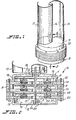
- FIGURE 1 is a perspective view of the electrical power generating device embodying the invention;
- FIGURE 2 is a central cross-sectional view taken along line 2-2 of Figure 1; and
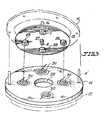
- FIGURE 3 is an exploded view showing one of a layer of the magnet-carrying rotatable plates and the coiled winding's stationary plate.
- Referring now in detail to the different views of the drawings, there is illustrated an electrical power generating device generally designated as 10. This device essentially comprises circular upper and
lower closure members rotatable plates 13 and coiled winding'sstationary plates 14 which are alternately disposed with each of saidrotatable plates 13 and superposedly fixed between saidclosure members blades 15 radially disposed vertically on saidupper closure members 11 having a downwardly extendingaxial shaft 16 securing horizontally said layer ofrotatable plates 13. - The
axial shaft 16 can also be driven by energy derived from flowing or falling waters, sea waves, steam generated by solar or geothermal energy engines, human and animal energy, solid and liquid biofuels, biogas, and other conventional fuels. - Each of said upper and
lower closure members horizontal walls circumferential side walls annular flanges flanges device 10 may be held by securing bolt B. Centrally disposed on each of said upper andlower members suitable bearings 25 and 26 are fitted. Journaled for rotation on thesebearings 25 and 26 is the downwardly extended portion E of theshaft 16. - Alternately secured with the upper and lower closure members and in superposed manner is the multi-layer of
rotatable plates 13 and thestationary plates 14. As best illustrated in Figure 3, each of therotatable plates 13 is circular in structure having a central opening with aprotruding skirt 27 which is secured to said extended shaft E. Radially spaced on each of saidrotatable plates 13 is a series of uniformcircular magnets 28 which are secured by suitable screws on its lower surface. Each of thestationary plates 14 which is diametrically of greater dimension comparably with therotatable plates 13 has acentral opening 29. Thesestationary plates 14 are spacedly held fixed in superposed manner with the said upper andlower closure members stationary plates 14 and spaced-apart thereof is a series of circular depressions each having coiledwindings 30 suitably secured thereto. - As best shown in Figure 2, the invention can be readily understood when any force of the wind impinges on the
blades 15 the velocity will rotate each of therotatable plates 13 carrying the magnets 26 continuously over each of thestationary plates 14 having coiled windings and thus produce electricity on its terminal through which power may be tapped to produce more or less 110 volts. However, when the terminals of each of the coiledwindings 30 are connected in series, a power of 220 volts will be generated.
Claims (5)
1. An electrical power generating device comprising of circular upper and lower members each having a horizontal wall and a converging side wall which terminate with an annular horizontal flange, each of said horizontal wall respectively having a central opening and a circular upright protrusion, a series of radially disposed windpowered arctuated blades upwardly extending rotatably on said upper closure member having a downwardly extending axial shaft rotatably secured on said members, a series of rotatable plates spacedly secured horizontally to said extended shaft, each of said rotatable plates having a series of spaced-apart magnets radially disposed underneath its lower surface, a series of stationary plates alternately disposed horizontally with said rotatable plates having a central opening and held fixed in superposed relation with the flange portion of said upper and lower members, each of said stationary plates having a series of spaced-apart circular depressions on its upper surface through which coiled windings are fitted in radial formation on each of said depressions and in communication with said magnets.
2. An electric power generating device as defined in claim 1, having a series or multi-layer of rotatable plates each having a series of magnets radially disposed on a series of stationary plates, each of said stationary plates being alternately disposed on each of the rotatable plates.
3. An electric power generating device as defined in claim 1, that is brushless and friction-less, with a high conversion efficiency which requires less force to operate and consumes no fuel in generating elecricity.
4. An electric power generating device as defined in claim 1, that can be driven by wind power of all forms, including chimney or flue draft, flowing or falling waters, sea waves, steam generated from solar or geothermal energy, human and animal energy, solid and liquid biofuels, biogas, and other conventional fuels.
5. An electric power generating device that is simple in structure, light and compact, and economical to manufacture.
Applications Claiming Priority (2)
| Application Number | Priority Date | Filing Date | Title |
|---|---|---|---|
| PH27137A PH22465A (en) | 1982-04-15 | 1982-04-15 | Electro power generating device |
| PH27137 | 1982-04-15 |
Publications (1)
| Publication Number | Publication Date |
|---|---|
| EP0091985A1 true EP0091985A1 (en) | 1983-10-26 |
Family
ID=19934902
Family Applications (1)
| Application Number | Title | Priority Date | Filing Date |
|---|---|---|---|
| EP82109072A Withdrawn EP0091985A1 (en) | 1982-04-15 | 1982-09-30 | Electro power generating device |
Country Status (4)
| Country | Link |
|---|---|
| EP (1) | EP0091985A1 (en) |
| JP (1) | JPS5921261A (en) |
| GB (1) | GB2118376A (en) |
| PH (1) | PH22465A (en) |
Cited By (9)
| Publication number | Priority date | Publication date | Assignee | Title |
|---|---|---|---|---|
| WO2003094329A1 (en) * | 2002-05-01 | 2003-11-13 | Makoto Ogoshi | Power generator and torque amplifier |
| GB2410064A (en) * | 2004-01-19 | 2005-07-20 | Ivan Mendez | A vertical axis wind powered generator |
| WO2005119886A2 (en) * | 2004-05-29 | 2005-12-15 | University Of Durham | Axial-flux, permanent magnet electrical machine |
| WO2009015907A2 (en) * | 2007-08-02 | 2009-02-05 | Turbo King Ltd | Improvements in or relating to energy generation |
| ES2336869A1 (en) * | 2007-07-13 | 2010-04-16 | Eoloton 67, S.L. (Sociedad En Constitucion) | Motor of permanent magnets situated asimetrically. (Machine-translation by Google Translate, not legally binding) |
| CN102255416A (en) * | 2011-07-22 | 2011-11-23 | 唐山市拓又达科技有限公司 | Vertical shaft multi-section type wind power generator shell |
| WO2012031968A1 (en) * | 2010-09-07 | 2012-03-15 | Evelin Sommer | Electrical generator and rotor blade assembly |
| EP2687337A3 (en) * | 2004-05-21 | 2016-06-01 | H & S Autoshot Manufacturing Company Limited | Pneumatic tool with integrated electricity generator |
| EP3455922A4 (en) * | 2016-05-20 | 2019-10-30 | Pacific International Energy Solutions Inc. | Pairs of complementary unidirectionally magnetic rotor/stator assemblies |
Families Citing this family (6)
| Publication number | Priority date | Publication date | Assignee | Title |
|---|---|---|---|---|
| JPS62166754A (en) * | 1986-01-20 | 1987-07-23 | Haiteku Kenkyusho:Kk | Brushless polyphase ac generator |
| JPS63113467U (en) * | 1987-01-12 | 1988-07-21 | ||
| JPH01154858A (en) * | 1987-12-14 | 1989-06-16 | Ube Ind Ltd | Method for controlling injection in die casting machine |
| JPH084912B2 (en) * | 1988-01-21 | 1996-01-24 | 宇部興産株式会社 | Injection control method of die casting machine |
| ES2331903B1 (en) * | 2007-07-13 | 2010-10-22 | Eoloton 67, S.L. (Sociedad En Constitucion) | VERTICAL HUB PERFORMANCE AEROGENERATOR WITH PERMANENT MAGNET ALTERNATOR. |
| RU2704805C2 (en) * | 2017-12-25 | 2019-10-31 | Андрей Александрович Яковенко | Universal cascade multiphase axial magnetoelectric generator |
Citations (6)
| Publication number | Priority date | Publication date | Assignee | Title |
|---|---|---|---|---|
| US3169204A (en) * | 1959-07-31 | 1965-02-09 | Normacem Sa | Axial air gap machines |
| US3219861A (en) * | 1961-03-06 | 1965-11-23 | Printed Motors Inc | Alternating-current generator |
| DE2248571A1 (en) * | 1972-10-04 | 1974-04-11 | Walter Schoenball | RINGDYNAMO / RING GENERATOR WIND POWER PLANT |
| US3832581A (en) * | 1972-03-31 | 1974-08-27 | G Jack | Multi-armature and concentric motors |
| GB2006542A (en) * | 1977-10-20 | 1979-05-02 | Gen Tech Inc | Multi-votage and multi-frequency alternator/generator of modular construction |
| EP0030357A2 (en) * | 1979-12-06 | 1981-06-17 | Siemens Aktiengesellschaft | Wind power wheel current generator |
Family Cites Families (4)
| Publication number | Priority date | Publication date | Assignee | Title |
|---|---|---|---|---|
| US1947269A (en) * | 1932-12-29 | 1934-02-13 | Gen Electric | Magneto-electric machine |
| FR1240693A (en) * | 1959-07-31 | 1960-09-09 | Normacem Sa | Rotating electric machine |
| US3407320A (en) * | 1965-11-29 | 1968-10-22 | Walter G Finch | Wafer type submersible motor for underwater device |
| GB1541211A (en) * | 1974-11-12 | 1979-02-28 | Pa Management Consult | Electro - magnetic machines |
-
1982
- 1982-04-15 PH PH27137A patent/PH22465A/en unknown
- 1982-09-30 EP EP82109072A patent/EP0091985A1/en not_active Withdrawn
-
1983
- 1983-03-02 GB GB08305707A patent/GB2118376A/en not_active Withdrawn
- 1983-04-12 JP JP58064389A patent/JPS5921261A/en active Pending
Patent Citations (6)
| Publication number | Priority date | Publication date | Assignee | Title |
|---|---|---|---|---|
| US3169204A (en) * | 1959-07-31 | 1965-02-09 | Normacem Sa | Axial air gap machines |
| US3219861A (en) * | 1961-03-06 | 1965-11-23 | Printed Motors Inc | Alternating-current generator |
| US3832581A (en) * | 1972-03-31 | 1974-08-27 | G Jack | Multi-armature and concentric motors |
| DE2248571A1 (en) * | 1972-10-04 | 1974-04-11 | Walter Schoenball | RINGDYNAMO / RING GENERATOR WIND POWER PLANT |
| GB2006542A (en) * | 1977-10-20 | 1979-05-02 | Gen Tech Inc | Multi-votage and multi-frequency alternator/generator of modular construction |
| EP0030357A2 (en) * | 1979-12-06 | 1981-06-17 | Siemens Aktiengesellschaft | Wind power wheel current generator |
Cited By (11)
| Publication number | Priority date | Publication date | Assignee | Title |
|---|---|---|---|---|
| WO2003094329A1 (en) * | 2002-05-01 | 2003-11-13 | Makoto Ogoshi | Power generator and torque amplifier |
| GB2410064A (en) * | 2004-01-19 | 2005-07-20 | Ivan Mendez | A vertical axis wind powered generator |
| EP2687337A3 (en) * | 2004-05-21 | 2016-06-01 | H & S Autoshot Manufacturing Company Limited | Pneumatic tool with integrated electricity generator |
| WO2005119886A2 (en) * | 2004-05-29 | 2005-12-15 | University Of Durham | Axial-flux, permanent magnet electrical machine |
| WO2005119886A3 (en) * | 2004-05-29 | 2006-08-03 | Univ Durham | Axial-flux, permanent magnet electrical machine |
| ES2336869A1 (en) * | 2007-07-13 | 2010-04-16 | Eoloton 67, S.L. (Sociedad En Constitucion) | Motor of permanent magnets situated asimetrically. (Machine-translation by Google Translate, not legally binding) |
| WO2009015907A2 (en) * | 2007-08-02 | 2009-02-05 | Turbo King Ltd | Improvements in or relating to energy generation |
| WO2009015907A3 (en) * | 2007-08-02 | 2009-10-29 | Turbo King Ltd | Improvements in or relating to energy generation |
| WO2012031968A1 (en) * | 2010-09-07 | 2012-03-15 | Evelin Sommer | Electrical generator and rotor blade assembly |
| CN102255416A (en) * | 2011-07-22 | 2011-11-23 | 唐山市拓又达科技有限公司 | Vertical shaft multi-section type wind power generator shell |
| EP3455922A4 (en) * | 2016-05-20 | 2019-10-30 | Pacific International Energy Solutions Inc. | Pairs of complementary unidirectionally magnetic rotor/stator assemblies |
Also Published As
| Publication number | Publication date |
|---|---|
| GB2118376A (en) | 1983-10-26 |
| GB8305707D0 (en) | 1983-04-07 |
| JPS5921261A (en) | 1984-02-03 |
| PH22465A (en) | 1988-09-12 |
Similar Documents
| Publication | Publication Date | Title |
|---|---|---|
| EP0091985A1 (en) | Electro power generating device | |
| EP0495872B1 (en) | Wind turbine | |
| US4306157A (en) | Underwater slow current turbo generator | |
| US4162410A (en) | Vertical-axis windmill | |
| US4184084A (en) | Wind driven gas generator | |
| US7772741B1 (en) | Wind turbine generator | |
| US3980894A (en) | Flow tubes for producing electric energy | |
| US4118636A (en) | Thermal air powered electric generator system | |
| US8692404B2 (en) | Chained assembly of hydroelectric power generators | |
| US4686376A (en) | Tide turbine | |
| US20010004439A1 (en) | Energy converter | |
| FR2810374B1 (en) | DEVICE FOR PRODUCING ELECTRIC CURRENT FROM WIND ENERGY | |
| US8461711B2 (en) | Counter rotation subsurface current generator | |
| WO2001023757A1 (en) | Steerable fluid current-powered turbine | |
| GB1601060A (en) | Double acting turbine for converting wave energy of water to electrical power | |
| CN211397766U (en) | Underwater turbine power generation device | |
| EP3276804A1 (en) | An apparatus for generating electricity | |
| US11754047B2 (en) | Wave, wind and tidal energy generator | |
| JPH10201219A (en) | Power source requiring no resource | |
| SU1712649A1 (en) | Water-power plant | |
| SU750125A1 (en) | Wave power plant | |
| KR20080077536A (en) | Electric generator | |
| WO2023248067A1 (en) | Electric power generator | |
| CN2043024U (en) | Miniature water turbogenerator | |
| WO2022249156A1 (en) | Wind turbine with rotational axis perpendicular to the wind flow |
Legal Events
| Date | Code | Title | Description |
|---|---|---|---|
| PUAI | Public reference made under article 153(3) epc to a published international application that has entered the european phase |
Free format text: ORIGINAL CODE: 0009012 |
|
| AK | Designated contracting states |
Designated state(s): AT BE CH DE FR IT LI NL SE |
|
| RBV | Designated contracting states (corrected) |
Designated state(s): AT BE CH DE FR IT LI NL SE |
|
| STAA | Information on the status of an ep patent application or granted ep patent |
Free format text: STATUS: THE APPLICATION IS DEEMED TO BE WITHDRAWN |
|
| 18D | Application deemed to be withdrawn |
Effective date: 19840625 |