EP0091983B1 - Unitized lip seal - Google Patents
Unitized lip seal Download PDFInfo
- Publication number
- EP0091983B1 EP0091983B1 EP82107033A EP82107033A EP0091983B1 EP 0091983 B1 EP0091983 B1 EP 0091983B1 EP 82107033 A EP82107033 A EP 82107033A EP 82107033 A EP82107033 A EP 82107033A EP 0091983 B1 EP0091983 B1 EP 0091983B1
- Authority
- EP
- European Patent Office
- Prior art keywords
- ring
- unitised
- lip seal
- sealing lip
- counter ring
- Prior art date
- Legal status (The legal status is an assumption and is not a legal conclusion. Google has not performed a legal analysis and makes no representation as to the accuracy of the status listed.)
- Expired
Links
Images
Classifications
-
- F—MECHANICAL ENGINEERING; LIGHTING; HEATING; WEAPONS; BLASTING
- F16—ENGINEERING ELEMENTS AND UNITS; GENERAL MEASURES FOR PRODUCING AND MAINTAINING EFFECTIVE FUNCTIONING OF MACHINES OR INSTALLATIONS; THERMAL INSULATION IN GENERAL
- F16J—PISTONS; CYLINDERS; SEALINGS
- F16J15/00—Sealings
- F16J15/16—Sealings between relatively-moving surfaces
- F16J15/32—Sealings between relatively-moving surfaces with elastic sealings, e.g. O-rings
- F16J15/3248—Sealings between relatively-moving surfaces with elastic sealings, e.g. O-rings provided with casings or supports
- F16J15/3252—Sealings between relatively-moving surfaces with elastic sealings, e.g. O-rings provided with casings or supports with rigid casings or supports
- F16J15/3256—Sealings between relatively-moving surfaces with elastic sealings, e.g. O-rings provided with casings or supports with rigid casings or supports comprising two casing or support elements, one attached to each surface, e.g. cartridge or cassette seals
- F16J15/3264—Sealings between relatively-moving surfaces with elastic sealings, e.g. O-rings provided with casings or supports with rigid casings or supports comprising two casing or support elements, one attached to each surface, e.g. cartridge or cassette seals the elements being separable from each other
-
- F—MECHANICAL ENGINEERING; LIGHTING; HEATING; WEAPONS; BLASTING
- F16—ENGINEERING ELEMENTS AND UNITS; GENERAL MEASURES FOR PRODUCING AND MAINTAINING EFFECTIVE FUNCTIONING OF MACHINES OR INSTALLATIONS; THERMAL INSULATION IN GENERAL
- F16J—PISTONS; CYLINDERS; SEALINGS
- F16J15/00—Sealings
- F16J15/16—Sealings between relatively-moving surfaces
- F16J15/32—Sealings between relatively-moving surfaces with elastic sealings, e.g. O-rings
- F16J15/3244—Sealings between relatively-moving surfaces with elastic sealings, e.g. O-rings with hydrodynamic pumping action
Definitions
- Cassette seal consisting of a U-ring with legs projecting in the direction of the relatively moving machine part and a firmly connected sealing lip made of rubber-elastic material, which rests under prestress against a hardened and / or smoothed running surface of the counter ring, the counter ring having a small axial distance of has the legs and is secured against rotation on the shaft by a damping layer made of flexible material.
- GB-A-879 503 refers to a cassette seal of the aforementioned type.
- the counter ring is mounted on a layer of rubber-elastic material and is axially enclosed by the legs of the outer ring extending inwards in the radial direction.
- the force required for installation can therefore only be transferred to the inner ring with the interposition of the legs of the outer ring, which leads to a rearward deformation of the rubber-elastic layer by the shaft. This cannot be compensated for automatically when the press-in force decreases.
- a defined assignment between the actual sealing lip and the counter ring in the axial direction is by no means guaranteed. It can lead to an unsatisfactory sealing result.
- the mating ring encloses the outer ring in the axial direction with two legs projecting outward in a U-shape.
- the counter ring is mounted on a rubber-elastic layer and has a coating made of the same material on the axial boundary surface of the one leg facing the outer ring. This serves as a wear layer and ensures a precise axial assignment between the two rings.
- the invention has for its object to show a cassette seal that has an improved wear behavior, reduced transmission losses and largely independent of the speed, a good sealing result.
- the mating ring of the proposed cassette seal has the shape of a hollow cylinder that is extremely easy to implement from a technical point of view. As a result, it can be manufactured cost-effectively using any materials, which enables optimal material pairings in relation to the achievement of a low coefficient of friction compared to the sealing lip.
- it is made of rubber or a plastic, for example PTFE, gray cast iron or nodular cast iron, sintered bronze and glass are preferably used in addition to steel, the actual running surface optionally being additionally smoothed and hardened.
- the material used for the production of a counter ring can thus be selected from a wide range, but it must not have any unbalanced internal tension that can lead to a change in the rotational symmetry during use. If wrought alloys made of metal are used, for example their type of deep-drawable materials, the creation of a one or both-sided axial offset must be avoided in connection with the manufacture of the hollow cylinder, because this inevitably extends into the hollow cylinder and over the Circumferentially distributed zones leads to a strong and less pronounced orientation of the crystallite structure.
- a corresponding offset therefore has a different surface structure distributed over the circumference and therefore unbalanced Friction as well as ripple. Both cannot be corrected by machining. If cold-drawn materials are used, it is important to note that the crystallite structure is continuously oriented in the circumferential or longitudinal direction. The required hollow cylinder can therefore not be obtained by punching out from a deep-drawn sheet, but preferably from tubular semi-finished products.
- Extruded and / or cold-drawn materials often have an absolutely rotationally symmetrical profile as well as a surface that is largely free of roughness due to the manufacturing process. For this reason, the use of such materials for the production of the counter ring is preferred.
- reworking by grinding and optionally polishing may be appropriate in individual cases. The costs incurred in this case are also comparatively low if the individual counter rings are cut to length after the corresponding machining operations.
- the sealing lip is connected to the U-ring by a thin, membrane-like transition piece, and as a result it can easily follow radial shaft displacements even when using relatively tough materials.
- a noteworthy extensibility is not necessary due to the absolute rotational symmetry of the counter ring and many materials can therefore be included in the considerations that previously seemed unsuitable for the production of a dynamically stressed sealing lip, for example PP or PES.
- a coating of the areas subject to friction with a thin film made of such a material can also be considered.
- the legs of the U-ring projecting in the radial direction overlap the axial end faces of the counter ring on both sides at a short distance.
- the short distance also has the effect of a labyrinth gap, through which the actual sealing zone is protected from pressure peaks of the sealed medium as well as from abrasive components from the area facing away from the medium. This results in a further improvement in the runtime.
- the sealing lip is arranged in a predominantly closed space and is assigned to the running surface of the counter ring from the outset in a very specific way. Neither improper storage nor improper installation can therefore damage the sealing lip and result in premature folding.
- the running surface of the counter ring has at least one swirl rib and / or swirl groove for returning leakage liquid that has penetrated under the sealing lip into the sealed space. This is preferably designed to merge into one another and, viewed over the circumference, has an alternating axial distance from the sealing lip.
- the hollow cylinder forming the counter ring can have ring projections on both sides, each of which overlaps the legs of the U-ring and which are at a radial distance from them. In addition to an extension of the labyrinth gap enclosed by both parts, this results in a further improved mutual assignment in the axial and radial directions.
- the labyrinth gap preferably has the same width in the area of the ring projections as in the area of the axial end faces of the hollow cylinder.
- the U-ring can be produced inexpensively from two angle rings which are sealingly connected by enclosing the counter ring. These can consist of metal or plastic, with the metallic design generally being preferred because of the greater robustness. At the same time, a design made of metal enables a sealing lip made of a rubber-elastic material to be molded directly onto one of the two angle rings by vulcanization, and at the same time a dust lip and / or a downstream lip Apply a rubber layer to seal against the other angle ring. In this case, the assembly of the individual parts only requires simple assembly and pressing.
- the use of the proposed cassette seal eliminates the need for fine machining and hardening of the relatively moving machine part compared to conventional radial shaft seals. This has no direct contact with the sealing lip, which is made of a polymeric material, it cannot shrink and even with repeated exchanges there is no need for machining to compensate for the surface of the shaft.
- the friction-specific conditions in the area of the sealing lip can be inexpensively optimized, as a result of which the thermal load on the sealing lip is significantly reduced, and it is a noteworthy advantage that improper storage and assembly can no longer cause a shortening of the running time.
- the cassette seal according to FIG. 1 consists of a liquid-tight and non-rotatably anchored U-ring 1 in the bore of a housing with the sealing lip 6 which is pressed by the helical spring 13 against the running surface of the counter ring 2 rotating with the shaft 11.
- the U-ring 1 consists of two angle rings made of deep-drawn sheet steel, namely the outer angle ring 4 and the inner angle ring 3. These are assembled in such a way that the legs of the profile which extend in the axial and radial directions have an approximately rectangularly limited cavity enclose.
- the dimensional accuracy of the two angle rings includes deviations from the absolute rotational symmetry within the usual tolerance limits. However, these deviations are of no importance insofar as there is no direct contact with relatively moving surfaces. In addition, there is a certain compensation of different deviations due to the force-fitting pressing into the rotationally symmetrical housing bore.
- the inner angle ring 3 is fixed to the outer angle ring 4 by a rubber layer 5 liquid-tight and secure against rotation.
- the rubber layer 5 is a direct component of the material body comprising the sealing lip 6 and the dust lip 7, which consists of rubber and is adhesively connected to the inner angle ring 3 by vulcanization.
- the Shore A hardness is 86 and the profiles of the sealing lip and dust lip correspond to those of the known radial shaft sealing rings. Radial shaft displacements can easily follow the sealing lip, which is made of a relatively hard material, by means of a constriction 15 which acts in an articulated manner.
- the dust lip is pressed against the running surface of the counter ring 2 solely by its pretensioning.
- an annular spiral spring 13 made of metal is provided to support the contact pressure. This favors a balanced contact pressure over long periods of time.
- the counter ring 2 is made of glass ceramic and has ring projections 9 on both sides, which overlap the legs of the U-ring 1 projecting inwards in the radial direction in the axial direction.
- ring projections 9 on both sides, which overlap the legs of the U-ring 1 projecting inwards in the radial direction in the axial direction.
- the end faces 14, of the counter ring 2 are on both sides at an axial distance of 0.2 mm from the legs of the U-ring 1 extending in the radial direction.
- the dust lip 7 is followed by a dirt deflector 8, which enables the cassette seal to be used under difficult conditions, for example in the area of the axle drive of earthmoving equipment.
- Figure 2 refers to the sealing of a hub with respect to a fixed axis 12. Because of the particular dirt load, a dirt deflector 8 is also provided in this case, which is connected downstream of the actual sealing lip. There is no dust lip and the tread is formed by the inside of the counter ring 2 rotating with the hub. For the pressing of the sealing lip, a compressible ring coil spring is provided, which is mounted radially inside the sealing lip in a groove.
- the counter ring 2 consists of a corrosion-resistant stainless steel and has a highly polished coating made of molybdenum to improve the abrasion resistance of the tread. Ring projections on both sides 9 and a damping layer 10 made of soft rubber, which is ribbed in the circumferential direction, facilitate the precise fitting.
Abstract
Description
Kassettendichtung, bestehend aus einem U-Ring mit in Richtung des relativ bewegten Maschinenteiles vorspringenden Schenkeln und einer fest verbundenen Dichtlippe aus gummielastischem Werkstoff, die unter einer Vorspannung an einer gehärteten und/oder geglätteten Lauffläche des Gegenringes anliegt, wobei der Gegenring einen geringen axialen Abstand von den Schenkeln aufweist und durch eine Dämpfungsschicht aus weichelastischem Werkstoff verdrehsicher auf der Welle festgelegt ist.Cassette seal, consisting of a U-ring with legs projecting in the direction of the relatively moving machine part and a firmly connected sealing lip made of rubber-elastic material, which rests under prestress against a hardened and / or smoothed running surface of the counter ring, the counter ring having a small axial distance of has the legs and is secured against rotation on the shaft by a damping layer made of flexible material.
Auf eine Kassettendichtung der vorgenannten Art nimmt die GB-A- 879 503 Bezug. Der Gegenring ist dabei auf einer Schicht aus gummielastischem Werkstoff gelagert und wird von den sich in radialer Richtung nach innen erstreckenden Schenkeln des Außenringes axial umschlossen. Die für den Einbau erforderliche Kraft kann daher nur unter Zwischenschaltung der Schenkel des Außenringes auf den Innenring übertragen werden, was zu einer rückwärts gerichteten Deformierung der gummielastischen Schicht durch die Welle führt. Diese kann bei Nachlassen der Einpreßkraft nicht selbsttätig ausgeglichen werden. Sie führt zu einer bleibenden axialen Verpressung zwischen dem Gegenring und dem sich in radialer Richtung nach innen erstreckenden Schenkel des Außenringes, über den die Einpressung vorgenommen worden ist. Neben den durch die hohe Reibung verursachten Übertragungsverlusten kann starker Verschleiß bzw. vorzeitiger Ausfall der Dichtung hiervon die Folge sein. Eine definierte Zuordnung zwischen der eigentlichen Dichtlippe und dem Gegenring in axialer Richtung ist keinesfalls gesichert. Sie kann zu einem unbefriedigenden Abdichtungsergebnis führen.GB-A-879 503 refers to a cassette seal of the aforementioned type. The counter ring is mounted on a layer of rubber-elastic material and is axially enclosed by the legs of the outer ring extending inwards in the radial direction. The force required for installation can therefore only be transferred to the inner ring with the interposition of the legs of the outer ring, which leads to a rearward deformation of the rubber-elastic layer by the shaft. This cannot be compensated for automatically when the press-in force decreases. It leads to permanent axial compression between the counter ring and the leg of the outer ring which extends inwards in the radial direction and via which the pressing-in was carried out. In addition to the transmission losses caused by the high friction, this can result in severe wear or premature failure of the seal. A defined assignment between the actual sealing lip and the counter ring in the axial direction is by no means guaranteed. It can lead to an unsatisfactory sealing result.
Bei der Kassettendichtung nach der GB-A- 881 607 umschließt der Gegenring den Außenring in axialer Richtung mit zwei U-förmig nach außen vorspringenden Schenkeln. Der Gegenring ist auf einer gummielastischen Schicht gelagert und weist eine aus dem gleichen Werkstoff bestehende Beschichtung auf der dem Außenring zugewandten, axialen Begrenzungsfläche des einen Schenkels auf. Diese dient als Schleißschicht und gewährleistet eine präzise axiale Zuordnung zwischen beiden Ringen.In the case of the cassette seal according to GB-A-881 607, the mating ring encloses the outer ring in the axial direction with two legs projecting outward in a U-shape. The counter ring is mounted on a rubber-elastic layer and has a coating made of the same material on the axial boundary surface of the one leg facing the outer ring. This serves as a wear layer and ensures a precise axial assignment between the two rings.
Sie bedingt zugleich hohe Übertragungsverluste zumindest während der Einlaufphase. Außerdem muß bei hohen Wellendrehzahlen ein hoher Verschleiß der Dichtlippe in Kauf genommen werden, weil die erforderliche Kühlung und Schmierung der Dichtlippe nicht mehr gegeben ist.At the same time, it causes high transmission losses, at least during the running-in phase. In addition, a high wear of the sealing lip must be accepted at high shaft speeds because the required cooling and lubrication of the sealing lip is no longer provided.
J.D. Symons nimmt in seinem Aufsatz "Elastohydrodynamic sealing systems", veröffentlicht auf dem International Automotive Engineering Congress, Detroit, Mich., 8.-12. Januar 1973, Nr. 730049, Seiten 1-8, Society of Automotive Engineers, Inc., New York, USA, Bezug auf eine Anordnung zur Abdichtung von Wellen, bei der einer mit hydrodynamisch wirkenden Rückförderelementen versehenen Welle ein von solchen Rückförderelementen freier Dichtring zugeordnet war. Ein befriedigendes Abdichtungsergebnis konnte dabei nur für eine Richtung der Drehbewegung erzielt werden. Eine Kassettendichtung mit hydrodynamisch wirkenden Rückförderelementen wurde nicht erwähnt.J.D. In its essay "Elastohydrodynamic sealing systems", published at the International Automotive Engineering Congress, Detroit, Mich., 8.-12. January 1973, No. 730049, pages 1-8, Society of Automotive Engineers, Inc., New York, USA, reference to an arrangement for sealing shafts, in which a shaft provided with hydrodynamically acting return elements is assigned a sealing ring free of such return elements was. A satisfactory sealing result could only be achieved for one direction of the rotary movement. A cassette seal with hydrodynamically acting return elements was not mentioned.
Der Erfindung liegt die Aufgabe zugrunde, eine Kassettendichtung zu zeigen, die ein verbessertes Verschleißverhalten, verminderte Übertagungsverluste sowie weitgehend unabhängig von der Drehzahl ein gutes Abdichtungsergebnis aufweist.The invention has for its object to show a cassette seal that has an improved wear behavior, reduced transmission losses and largely independent of the speed, a good sealing result.
Diese Aufgabe wird erfindungsgemäß bei einer Kassettendichtung der eingangs genannten Art dadurch gelöst, daß der Gegenring freiliegende Ringvorsprünge zum Einpressen der Kassettendichtung in den Spalt zwischen Welle und Gehäusebohrung aufweist, daß die Dämpfungsschicht eine Rückfederung aufweist, die bei Nachlassen der Einpreßkraft einen Ausgleich des axialen Spiels zwischen den Schenkeln und dem Gegenring bewirkt, daß die Lauffläche mit wenigstens einer Drallrippe und/oder Drallnute zur Rückförderung unter der Dichtlippe hindurchgedrungener Leckflüssigkeit in den abgedichteten Raum versehen ist.This object is achieved with a cassette seal of the type mentioned in that the counter ring has exposed ring projections for pressing the cassette seal into the gap between the shaft and the housing bore, that the damping layer has a springback that compensates for the axial play between when the press-in force decreases the legs and the counter ring has the effect that the running surface is provided with at least one swirl rib and / or swirl groove for returning leakage liquid which has penetrated under the sealing lip into the sealed space.
Der Gegenring der vorgeschlagenen Kassettendichtung hat die in technischer Hinsicht außerordentlich einfach zu realisierende Gestalt eines Hohlzylinders. Seine Herstellung ist dadurch kostengünstig möglich unter Verwendung beliebiger Werkstoffe, was optimale Werkstoffpaarungen in bezug auf die Erzielung eines niedrigen Reibungskoeffizienten gegenüber der Dichtlippe ermöglicht. In Fällen, in denen diese aus Gummi oder einem Kunststoff besteht, beispielsweise aus PTFE, kommen neben Stahl bevorzugt Grau- oder Kugelgraphitguß, Sinterbronze und Glas zur Anwendung, wobei die eigentliche Lauffläche gegebenenfalls zusätzlich geglättet und gehärtet sein kann.The mating ring of the proposed cassette seal has the shape of a hollow cylinder that is extremely easy to implement from a technical point of view. As a result, it can be manufactured cost-effectively using any materials, which enables optimal material pairings in relation to the achievement of a low coefficient of friction compared to the sealing lip. In cases where it is made of rubber or a plastic, for example PTFE, gray cast iron or nodular cast iron, sintered bronze and glass are preferably used in addition to steel, the actual running surface optionally being additionally smoothed and hardened.
Das für die Herstellung eines Gegenringes verwendete Material ist somit aus einem großem Spektrum wählbar, es darf jedoch keinerlei unausgeglichene innere Spannung aufweisen, die zu einer Veränderung der Rotationssymmetrie während des Gebrauchs führen kann. Sofern Knetlegierungen aus Metall zur Anwendung kommen, beispielsweise ihrer Art nach tiefziehbare Materialien, ist deshalb in Zusammenhang mit der Herstellung des Hohlzylinders die Erzeugung einer ein- oder beidseitigen, axialen Abkröpfung unbedingt zu vermeiden, weil diese zwangsläufig zu sich in den Hohlzylinder hineinerstreckenden, über den Umfang verteilten Zonen einer stark und weniger stark ausgeprägten Orientierung der Kristallitstruktur führt.The material used for the production of a counter ring can thus be selected from a wide range, but it must not have any unbalanced internal tension that can lead to a change in the rotational symmetry during use. If wrought alloys made of metal are used, for example their type of deep-drawable materials, the creation of a one or both-sided axial offset must be avoided in connection with the manufacture of the hollow cylinder, because this inevitably extends into the hollow cylinder and over the Circumferentially distributed zones leads to a strong and less pronounced orientation of the crystallite structure.
Eine entsprechende Abkröpfung hat deshalb eine auf den Umfang verteilte, unterschiedliche Oberflächenstruktur und damit unausgeglichene Reibungsverhältnisse ebenso zur Folge wie eine Welligkeit. Beides läßt sich durch eine spanabhebende Bearbeitung nicht korrigieren. Sofern kaltgezogene Materialien zur Anwendung kommen, ist unbedingt zu beachten, daß die Kristallitstruktur durchgehend in Umfangs- oder Längsrichtung oerientiert ist. Der benötigte Hohlzylinder läßt sich deshalb nicht durch Ausstanzen aus einem Tiefziehblech gewinnen, sondern bevorzugt aus rohrförmig angelieferten Halbzeugen.A corresponding offset therefore has a different surface structure distributed over the circumference and therefore unbalanced Friction as well as ripple. Both cannot be corrected by machining. If cold-drawn materials are used, it is important to note that the crystallite structure is continuously oriented in the circumferential or longitudinal direction. The required hollow cylinder can therefore not be obtained by punching out from a deep-drawn sheet, but preferably from tubular semi-finished products.
Stranggepreßte und/oderkaltgezogene Materialien haben häufig herstellungsbedingt sowohl ein absolut rotationssymmetrisches Profil als auch eine weitestgehend von Rauhigkeiten freie Oberfläche. Die Verwendung derartiger Materialien zur Herstellung des Gegenringes wird aus diesem Grunde bevorzugt. Bei auf andere Weise erhaltenen Materialien kann im Einzelfalle eine Nachbearbeitung durch Schleifen und gegebenenfalls Polieren zweckmäßig sein. Auch die in diesem falle entstehenden Kosten sind vergleichsweise gering, wenn das Ablängen der einzelnen Gegenringe den entsprechenden Bearbeitungsvorgängen nachgeschaltet ist.Extruded and / or cold-drawn materials often have an absolutely rotationally symmetrical profile as well as a surface that is largely free of roughness due to the manufacturing process. For this reason, the use of such materials for the production of the counter ring is preferred. In the case of materials obtained in a different way, reworking by grinding and optionally polishing may be appropriate in individual cases. The costs incurred in this case are also comparatively low if the individual counter rings are cut to length after the corresponding machining operations.
Einige der vorgenannten Werkstoffe zeichnen sich nicht nur durch eine große Härte der Oberfläche aus, was außerordentlich positiv ist, sondern zusätzlich durch eine große Sprödigkeit, die eine Zerstörung beim Einbau oder als Folge der unterschiedlichen Wärmedehnung eines unmittelbar anliegenden Maschinenteiles zur Folge haben kann. Derartige Schwierigkeiten treten bei der vorgeschlagenen Ausführung jedoch nicht auf. Die Dämpfungsschicht bewirkt vielmehr einen Ausgleich derart verursachter Spannungen sowie eine gute statische Abdichtung gegenüber dem angrenzenden Maschinenteil. Sie ist darüber hinaus so mit dem axialen Spiel zwischen den Stirnflächen des Gegenringes und den nach innen vorspringenden Schenkeln des Außenringes abgestimmt, daß die Rückfederung der Dämpfungsschicht bei Nachlassen der über den Ringvorsprung aufgebrachten Einpreßkräfte einen selbsttätigen Ausgleich dieses Spiels bewirkt. Außen- und Innenring können insofern einander nicht beschädigen und die übertragung der Drehbewegung hemmen. Innenring und Dichtlippe können sowohl werkstoffmäßig als auch hinsichtlich ihrer speziellen Ausbildung unter Ausklammerung der diesbezüglichen Probleme aneinander angepaßt werden, was es erlaubt, ein verbessertes Abdichtungsergebnis bei vermindertem Verschleiß und verminderten Übertragungsverlusten zu erzielen.Some of the above-mentioned materials are not only characterized by a high hardness of the surface, which is extremely positive, but also by a great brittleness, which can result in destruction during installation or as a result of the different thermal expansion of an adjacent machine part. However, such difficulties do not occur with the proposed design. Rather, the damping layer compensates for stresses caused in this way and provides a good static seal with respect to the adjacent machine part. It is also so matched with the axial play between the end faces of the counter ring and the inwardly projecting legs of the outer ring that the resilience of the damping layer causes an automatic compensation of this play when the press-in forces applied via the ring projection decrease. In this respect, the outer and inner rings cannot damage each other and inhibit the transmission of the rotary movement. Inner ring and sealing lip can be adapted to each other both in terms of material and in terms of their special design, excluding the related problems, which makes it possible to achieve an improved sealing result with reduced wear and reduced transmission losses.
Die Dichtlippe ist durch ein dünnes, membranartig ausgebildetes Übergangsstück mit dem U-Ring verbunden, und sie vermag dadurch radialen Wellenverlagerungen auch bei Verwendung relativ zäher Werkstoffe leicht zu folgen. Eine nennenswerte Dehnbarkeit ist wegen der absoluten Rotationssymmetrie des Gegenringes nicht erforderlich und es können daher viele Werkstoffe in die Überlegungen einbezogen werden, die bisher für die Herstellung einer dynamisch beanspruchten Dichtlippe nicht geeignet schienen, beispielsweise PP oder PES. Auch eine Beschichtung der auf Reibung beanspruchten Bereiche mit einer dünnen Folie aus einem solchen Werkstoff kommt in Betracht.The sealing lip is connected to the U-ring by a thin, membrane-like transition piece, and as a result it can easily follow radial shaft displacements even when using relatively tough materials. A noteworthy extensibility is not necessary due to the absolute rotational symmetry of the counter ring and many materials can therefore be included in the considerations that previously seemed unsuitable for the production of a dynamically stressed sealing lip, for example PP or PES. A coating of the areas subject to friction with a thin film made of such a material can also be considered.
Die in radialer Richtung vorspringenden Schenkel des U-Ringes überlappen die axialen Stirnflächen des Gegenringes beiderseits in einem geringen Abstand.The legs of the U-ring projecting in the radial direction overlap the axial end faces of the counter ring on both sides at a short distance.
Der geringe Abstand hat zugleich die Wirkung eines Labyrinthspaltes, durch den die eigentliche Dichtungszone ebenso vor Druckspitzen des abgedichteten Mediums geschützt wird wie vor abrasiv wirkenden Bestandteilen aus dem mediumsabgewandten Bereich. Eine weitere Verbesserung der Laufzeit ist hiervon die Folge.The short distance also has the effect of a labyrinth gap, through which the actual sealing zone is protected from pressure peaks of the sealed medium as well as from abrasive components from the area facing away from the medium. This results in a further improvement in the runtime.
Die Dichtlippe ist bei der vorgeschlagenen Kassettendichtung in einem überwiegend nach außen geschlossenen Raum angeordnet und der Lauffläche des Gegenringes von vornherein in einer ganz bestimmten Weise zugeordnet. Weder eine unsachgemäße Lagerung, noch eine unsachgemäße Montage können daher zu einer Beschädigung der Dichtlippe führen und einen vorzeitigen Ausfalt zur Folge haben.In the case of the proposed cassette seal, the sealing lip is arranged in a predominantly closed space and is assigned to the running surface of the counter ring from the outset in a very specific way. Neither improper storage nor improper installation can therefore damage the sealing lip and result in premature folding.
Die Lauffläche des Gegenringes weist zur Erzielung der dynamischen Abdichtwirkung wenigstens eine Drallrippe und/oder Drallnute zur Rückförderung unter der Dichtlippe hindurchgedrungener Leckflüssigkeit in den abgedichteten Raum auf. Diese ist bevorzugt ineinander übergehend ausgebildet und weist, über den Umfang gesehen, einen wechselnden, axialen Abstand von der Dichtlippe auf.To achieve the dynamic sealing effect, the running surface of the counter ring has at least one swirl rib and / or swirl groove for returning leakage liquid that has penetrated under the sealing lip into the sealed space. This is preferably designed to merge into one another and, viewed over the circumference, has an alternating axial distance from the sealing lip.
In Fällen, in denen mehrere derartige Drallrippen und/oder Drallnuten vorhanden sind, hat es sich als zweckmäßig erwiesen, diese untereinander identisch auszubilden und in gleichmäßig auf den Umfang verteilten Abständen anzuordnen.In cases in which several such swirl ribs and / or swirl grooves are present, it has proven to be expedient to design them identically to one another and to arrange them at intervals that are evenly distributed over the circumference.
Der den Gegenring bildende Hohlzylinder kann beiderseitige Ringvorsprünge aufweisen, die die Schenkel des U-Ringes jeweils übergreifen und die von diesen einen radialen Abstand haben. Neben einer Verlängerung des von beiden Teilen eingeschlossenen Labyrinthspaltes resultiert eine nochmals verbesserte gegenseitige Zuordnung in axialer und radialer Richtung. Der Labyrinthspalt hat bevorzugt im Bereich der Ringvorsprünge dieselbe Breite wie im Bereich der axialen Stirnflächen des Hohlzylinders.The hollow cylinder forming the counter ring can have ring projections on both sides, each of which overlaps the legs of the U-ring and which are at a radial distance from them. In addition to an extension of the labyrinth gap enclosed by both parts, this results in a further improved mutual assignment in the axial and radial directions. The labyrinth gap preferably has the same width in the area of the ring projections as in the area of the axial end faces of the hollow cylinder.
Der U-Ring läßt sich kostengünstig aus zwei unter Einschließung des Gegenringes dichtend verbundenen Winkelringen erzeugen. Diese können aus Metall oder Kunststoff bestehen, wobei der metallischen Ausführung wegen der größeren Robustheit im allgemeinen der Vorzug gegeben wird. Zugleich ermöglicht es eine Ausführung aus Metall, eine Dichtlippe aus einem gummielastischen Werkstoff durch Vulkanisation unmittelbar an einen der beiden Winkelringe anzuformen und dabei zugleich eine eventuell nachgeschaltete Staublippe und/oder eine Gummischicht zur Abdichtung gegenüber dem anderen Winkelring anzubringen. Der Zusammenbau der einzelnen Teile erfordert in diesem Falle lediglich ein einfaches Zusammenfügen und Verpressen.The U-ring can be produced inexpensively from two angle rings which are sealingly connected by enclosing the counter ring. These can consist of metal or plastic, with the metallic design generally being preferred because of the greater robustness. At the same time, a design made of metal enables a sealing lip made of a rubber-elastic material to be molded directly onto one of the two angle rings by vulcanization, and at the same time a dust lip and / or a downstream lip Apply a rubber layer to seal against the other angle ring. In this case, the assembly of the individual parts only requires simple assembly and pressing.
Die Verwendung der vorgeschlagenen Kassettendichtung erübrigt im Vergleich zu üblichen Rsdialwellendichtringen eine Feinbearbeitung und Härtung des relativ bewegten Maschinenteils. Dieses hat keinerlei unmittelbaren Kontakt zu der aus einem polymeren Werkstoff bestehenden Dichtlippe, es kann nicht einlaufen und auch bei wiederholtem Austausch erübrigt sich eine die Oberfläche der Welle ausgleichende Bearbeitung. Die reibungsspezifischen Verhältnisse im Bereich der Dichtlippe lassen sich kostengünstig optimieren, wodurch die thermische Belastung der Dichtlippe wesentlich vermindert ist, und es ist ein hervorzuhebender Vorteil, daß eine unsachgemäße Lagerung und Montage regelmäßig eine Verkürzung der Laufzeit nicht mehr verursachen kann.The use of the proposed cassette seal eliminates the need for fine machining and hardening of the relatively moving machine part compared to conventional radial shaft seals. This has no direct contact with the sealing lip, which is made of a polymeric material, it cannot shrink and even with repeated exchanges there is no need for machining to compensate for the surface of the shaft. The friction-specific conditions in the area of the sealing lip can be inexpensively optimized, as a result of which the thermal load on the sealing lip is significantly reduced, and it is a noteworthy advantage that improper storage and assembly can no longer cause a shortening of the running time.
Der Gegenstand der vorliegenden Erfindung wird nachfolgend anhand der in der Anlage beigefügten-Zeichnung weiter verdeutlicht. Es zeigen:
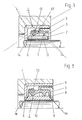
- Figur 1 eine Kassettendichtung für den Spalt zwischen einer Gehäusewandung und einer sich drehenden Welle, bei der der Gegenring mit Ringvorsprüngen versehen ist und bei der ein zusätzlicher Schmutzabweiser der Staublippe nachgeschaltet ist.
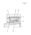
Figur 2 eine Kassettendichtung für den Spalt zwischen einem umlaufenden Gehäuse und einer ruhenden Achse.
- 1 shows a cassette seal for the gap between a housing wall and a rotating shaft, in which the counter ring is provided with ring projections and in which an additional dirt deflector is connected downstream of the dust lip.
- Figure 2 shows a cassette seal for the gap between a circumferential housing and a stationary axis.
Die Kassettendichtung gemäß Figur 1 besteht aus einem flüssigkeitsdicht und verdrehsicher in der Bohrung eines Gehäuses verankerten U-Ring 1 mit der Dichtlippe 6, die von der Ringwendelfeder 13 gegen die Lauffläche des mit der Welle 11 umlaufenden Gegenringes 2 gedrückt wird.The cassette seal according to FIG. 1 consists of a liquid-tight and non-rotatably anchored U-ring 1 in the bore of a housing with the sealing
Der U-Ring 1 besteht aus zwei durch Tiefziehen erzeugten Winkelringen aus Stahlblech, nämlich dem äußeren Winkelring 4 und dem inneren Winkelring 3. Diese sind derart zusammengefügt, daß die sich in axialer und in radialer Richtung erstreckenden Schenkel des Profils einen in etwa rechteckig begrenzten Hohlraum umschließen. Die Maßhaltigkeit der beiden Winkelringe schließt Abweichungen von der absoluten Rotationssymmetrie in den üblichen Toleranzgrenzen ein. Diese Abweichungen sind jedoch insofern ohne entscheidende Bedeutung als ein unmittelbarer Kontakt zu relativ bewegten Flächen nicht vorhanden ist. Außerdem ergibt sich durch die kraftschlüssige Einpressung in die rotationssymmetrisch erzeugte Gehäusebohrung ein gewisser Ausgleich von unterschiedlichen Abweichungen.The U-ring 1 consists of two angle rings made of deep-drawn sheet steel, namely the
Der innere Winkelring 3 ist gegenüber dem äußeren Winkelring 4 durch eine Gummischicht 5 flüssigkeitsdicht und verdrehsicher festgelegt. Die Gummischicht 5 ist ein unmittelbarer Bestandteil des die Dichtlippe 6 und die Staublippe 7 umfassenden Werkstoffkörpers, der aus Gummi besteht und durch Vulkanisation adhäsiv mit dem inneren Winkelring 3 verbunden ist. Die Härte Shore A beträgt 86 und die Profile von Dichtlippe und Staublippe entsprechen denjenigen der bekannten Radialwellendichtringe. Radialen Wellenverlagerungen vermag die aus einem relativ harten Werkstoff bestehende Dichtlippe durch eine gelenkartig wirkende Einschnürung 15 leicht zu folgen. Die Staublippe wird allein durch ihre Vorspannung gegen die Lauffläche des Gegenringes 2 gedrückt, bei der Dichtlippe ist zur Unterstützung der Anpressung eine Ringwendelfeder 13 aus Metall vorgesehen. Hierdurch wird eine ausgeglichene Anpressung über lange Zeiträume begünstigt.The
Der Gegenring 2 besteht aus Glaskeramik und weist beiderseitige Ringvorsprünge 9 auf, die die in radialer Richtung nach innen vorspringenden Schenkel des U-Ringes 1 in axialer Richtung übergreifen. Hierdurch wird eine verbesserte radiale und axiale gegenseitige Zuordnung erreicht. Das axiale Spiel zwischen den Stirnflächen und den nach innen vorspringenden Schenkeln des U-Ringes 1 gleicht sich außerdem durch die Rückfederung der Dämpfungsschicht 10 bei Nachlassen der Einpreßkraft selbsttätig aus, wenn die Einpressung in den Spalt zwischen der Welle 11 und der Gehäusebohrung durch eine Kraftausübung auf den freiliegenden Ringvorsprung 9 vorgenommen wird.The
Die Stirnflächen 14, des Gegenringes 2 haben beiderseits einen axialen Abstand von den sich in radialer Richtung erstreckenden Schenkeln des U-Ringes 1 von jeweils 0,2 mm.The end faces 14, of the
Der Staublippe 7 ist in diesem Falle jedoch ein Schmutzabweiser 8 nachgeschaltet, der eine Verwendung der Kassettendichtung unter erschwerten Bedingungen ermöglicht, beispielsweise im Bereich des Achsantriebes von Erdbewegungsgeräten.In this case, however, the
Figur 2 nimmt Bezug auf die Abdichtung einer Nabe gegenüber einer feststehenden Achse 12. Wegen der besonderen Schmutzbelastung ist auch in diesem Falle ein Schmutzabweiser 8 vorgesehen, der der eigentlichen Dichtlippe nachgeschaltet ist. Eine Staublippe ist nicht vorhanden und die Lauffläche wird durch die Innenseite des mit der Nabe umlaufenden Gegenringes 2 gebildet. Für die Anpressung der Dichtlippe ist eine auf Druck beanspruchbare Ringwendelfeder vorgesehen, die radial innerhalb der Dichtlippe in einer Nute gelagert ist.Figure 2 refers to the sealing of a hub with respect to a fixed
Der Gegenring 2 besteht aus einem korrosionsfesten Edelstahl und weist eine hochglanzpolierte Beschichtung aus Molybdän zur Verbesserung der Abriebbeständigkeit der Lauffläche auf. Beiderseitige Ringvorsprünge 9 und eine in Umfangsrichtung gerippte Dämpfungsschicht 10 aus Weichgummi erleichtern die paßgenaue Montage.The
Claims (5)
Priority Applications (1)
| Application Number | Priority Date | Filing Date | Title |
|---|---|---|---|
| AT82107033T ATE23393T1 (en) | 1982-04-15 | 1982-08-04 | CASSETTE SEAL. |
Applications Claiming Priority (2)
| Application Number | Priority Date | Filing Date | Title |
|---|---|---|---|
| DE3213809A DE3213809C2 (en) | 1982-04-15 | 1982-04-15 | Cassette seal |
| DE3213809 | 1982-04-15 |
Publications (2)
| Publication Number | Publication Date |
|---|---|
| EP0091983A1 EP0091983A1 (en) | 1983-10-26 |
| EP0091983B1 true EP0091983B1 (en) | 1986-11-05 |
Family
ID=6160938
Family Applications (1)
| Application Number | Title | Priority Date | Filing Date |
|---|---|---|---|
| EP82107033A Expired EP0091983B1 (en) | 1982-04-15 | 1982-08-04 | Unitized lip seal |
Country Status (5)
| Country | Link |
|---|---|
| US (1) | US4436317A (en) |
| EP (1) | EP0091983B1 (en) |
| JP (1) | JPS58191373A (en) |
| AT (1) | ATE23393T1 (en) |
| DE (2) | DE3213809C2 (en) |
Families Citing this family (18)
| Publication number | Priority date | Publication date | Assignee | Title |
|---|---|---|---|---|
| JPS6078168A (en) * | 1983-10-04 | 1985-05-02 | Nok Corp | Seal |
| DE3414008C2 (en) * | 1984-04-13 | 1986-03-13 | Fa. Carl Freudenberg, 6940 Weinheim | Cassette seal |
| FR2598478A1 (en) * | 1986-05-12 | 1987-11-13 | Gudin Michel | Lip-type sealing ring provided with an integral revolving friction bush |
| JPH0512535Y2 (en) * | 1986-09-26 | 1993-03-31 | ||
| DE3811227C2 (en) * | 1988-04-02 | 1996-04-11 | Freudenberg Carl Fa | Ferrofluid seal |
| GB8925421D0 (en) * | 1989-11-10 | 1989-12-28 | Boc Group Plc | Shaft sealing arrangements |
| US5082294A (en) * | 1990-09-20 | 1992-01-21 | Federal-Mogul Corporation | Heat conducting wear sleeve assembly for lubricant seals |
| US5209499A (en) * | 1992-05-26 | 1993-05-11 | Mather Seal Company | Unitized polytetrafluoroethylene radial lip seal |
| FR2706565B1 (en) * | 1993-06-14 | 1995-09-01 | Piv Sa | Seal for rotating shaft. |
| US5533737A (en) * | 1994-10-21 | 1996-07-09 | Garlock Inc. | Seals with particle exclusion means |
| US6186507B1 (en) | 1997-09-25 | 2001-02-13 | Michael R. Oldenburg | Retrofittable severe duty seal for a shaft |
| US20020011710A1 (en) | 1997-09-25 | 2002-01-31 | Oldenburg Michael R. | Retrofittable severe duty seal for a shaft |
| US6692007B2 (en) | 2001-10-31 | 2004-02-17 | Transcom, Inc. | Seal for a shaft |
| US8029714B2 (en) * | 2005-09-12 | 2011-10-04 | Federal-Mogul World Wide, Inc. | Radial seal and method of making |
| US8480092B2 (en) * | 2005-09-12 | 2013-07-09 | Federal-Mogul World Wide, Inc. | Radial seal and method of making |
| US9212748B2 (en) * | 2009-09-08 | 2015-12-15 | Aktiebolaget Skf | Floating wear sleeve assembly for shaft seals |
| CN102837749A (en) * | 2012-09-27 | 2012-12-26 | 青岛开世密封工业有限公司 | Muddy water preventing structure of track wheel |
| DE102013110247A1 (en) * | 2013-09-17 | 2015-03-19 | Thyssenkrupp Rothe Erde Gmbh | Process for the surface treatment of a pivot bearing and protective seal arrangement for carrying out the method |
Family Cites Families (5)
| Publication number | Priority date | Publication date | Assignee | Title |
|---|---|---|---|---|
| GB590874A (en) * | 1945-04-25 | 1947-07-30 | Angus George Co Ltd | Improvements relating to oil seals |
| AT185634B (en) * | 1953-07-07 | 1956-05-25 | Daimler Benz Ag | Shaft seal |
| GB881607A (en) * | 1959-09-14 | 1961-11-08 | Federal Mogul Bower Bearings | Fluid sealing means between two relatively rotating members |
| GB879503A (en) * | 1960-04-20 | 1961-10-11 | Federal Mogul Bower Bearings | Fluid sealing means between two relatively rotating members |
| US3510138A (en) * | 1965-10-15 | 1970-05-05 | Federal Mogul Corp | Oil seal with rock shield and wear sleeve |
-
1982
- 1982-04-15 DE DE3213809A patent/DE3213809C2/en not_active Expired
- 1982-08-04 EP EP82107033A patent/EP0091983B1/en not_active Expired
- 1982-08-04 AT AT82107033T patent/ATE23393T1/en active
- 1982-08-04 DE DE8282107033T patent/DE3274145D1/en not_active Expired
-
1983
- 1983-01-07 US US06/456,447 patent/US4436317A/en not_active Expired - Fee Related
- 1983-04-14 JP JP58066293A patent/JPS58191373A/en active Granted
Also Published As
| Publication number | Publication date |
|---|---|
| US4436317A (en) | 1984-03-13 |
| JPS58191373A (en) | 1983-11-08 |
| ATE23393T1 (en) | 1986-11-15 |
| JPS6343623B2 (en) | 1988-08-31 |
| EP0091983A1 (en) | 1983-10-26 |
| DE3213809C2 (en) | 1984-06-20 |
| DE3274145D1 (en) | 1986-12-11 |
| DE3213809A1 (en) | 1983-11-03 |
Similar Documents
| Publication | Publication Date | Title |
|---|---|---|
| EP0091983B1 (en) | Unitized lip seal | |
| EP0268624B1 (en) | Seal arrangement | |
| DE3505464C2 (en) | Cassette seal for shafts | |
| EP0086250A1 (en) | Oil seal assembly | |
| EP0431263A1 (en) | Seal unit | |
| DE3511333A1 (en) | UNIFIED SEALS AND METHOD FOR ASSEMBLING THEM | |
| DE19914921C2 (en) | seal | |
| EP1406025A2 (en) | Rotary shaft lip seal | |
| DE2748156A1 (en) | SEAL FOR PENDULUM BEARINGS AND METHOD OF MANUFACTURING IT | |
| DE69819602T2 (en) | Radial shaft seal | |
| EP0266479B1 (en) | Torsional oscillation damper with an integrated shrink ring | |
| EP0137092B1 (en) | Shaft seal | |
| DE102010054409A1 (en) | Sealing device and pivot bearing with this | |
| EP0596196B1 (en) | Sealing arrangement | |
| DE3209926C2 (en) | Lip seal | |
| DE112018003269T5 (en) | Sealing ring | |
| EP0798498A1 (en) | Radial lip seal with excluding effect independent of the rotation direction | |
| DE19648602C2 (en) | Sealing arrangement | |
| DE19539057A1 (en) | Radial shaft sealing ring, for shaft rotating in either direction | |
| DE102012001226A1 (en) | Shaft seal, in particular radial shaft seal | |
| EP0525289A1 (en) | Cartridge sealing | |
| DE4225556A1 (en) | Rod guide supported between radially inwards cylinder face protrusions - which are axially spaced from rod guide, with intermediate space filled by rubber layer | |
| DE4018796C2 (en) | ||
| EP0736711A1 (en) | Sealing arrangement | |
| DE19726433C2 (en) | Sealing arrangement |
Legal Events
| Date | Code | Title | Description |
|---|---|---|---|
| PUAI | Public reference made under article 153(3) epc to a published international application that has entered the european phase |
Free format text: ORIGINAL CODE: 0009012 |
|
| 17P | Request for examination filed |
Effective date: 19830823 |
|
| AK | Designated contracting states |
Designated state(s): AT BE CH DE FR GB IT LI LU NL SE |
|
| ITF | It: translation for a ep patent filed |
Owner name: BARZANO' E ZANARDO ROMA S.P.A. |
|
| GRAA | (expected) grant |
Free format text: ORIGINAL CODE: 0009210 |
|
| AK | Designated contracting states |
Kind code of ref document: B1 Designated state(s): AT BE CH DE FR GB IT LI LU NL SE |
|
| REF | Corresponds to: |
Ref document number: 23393 Country of ref document: AT Date of ref document: 19861115 Kind code of ref document: T |
|
| REF | Corresponds to: |
Ref document number: 3274145 Country of ref document: DE Date of ref document: 19861211 |
|
| ET | Fr: translation filed | ||
| PLBE | No opposition filed within time limit |
Free format text: ORIGINAL CODE: 0009261 |
|
| STAA | Information on the status of an ep patent application or granted ep patent |
Free format text: STATUS: NO OPPOSITION FILED WITHIN TIME LIMIT |
|
| 26N | No opposition filed | ||
| ITTA | It: last paid annual fee | ||
| EPTA | Lu: last paid annual fee | ||
| PGFP | Annual fee paid to national office [announced via postgrant information from national office to epo] |
Ref country code: CH Payment date: 19940720 Year of fee payment: 13 |
|
| PGFP | Annual fee paid to national office [announced via postgrant information from national office to epo] |
Ref country code: DE Payment date: 19940727 Year of fee payment: 13 |
|
| PGFP | Annual fee paid to national office [announced via postgrant information from national office to epo] |
Ref country code: GB Payment date: 19940729 Year of fee payment: 13 |
|
| PGFP | Annual fee paid to national office [announced via postgrant information from national office to epo] |
Ref country code: LU Payment date: 19940801 Year of fee payment: 13 |
|
| PGFP | Annual fee paid to national office [announced via postgrant information from national office to epo] |
Ref country code: BE Payment date: 19940809 Year of fee payment: 13 |
|
| PGFP | Annual fee paid to national office [announced via postgrant information from national office to epo] |
Ref country code: AT Payment date: 19940810 Year of fee payment: 13 |
|
| PGFP | Annual fee paid to national office [announced via postgrant information from national office to epo] |
Ref country code: FR Payment date: 19940817 Year of fee payment: 13 |
|
| PGFP | Annual fee paid to national office [announced via postgrant information from national office to epo] |
Ref country code: SE Payment date: 19940831 Year of fee payment: 13 Ref country code: NL Payment date: 19940831 Year of fee payment: 13 |
|
| EAL | Se: european patent in force in sweden |
Ref document number: 82107033.1 |
|
| PG25 | Lapsed in a contracting state [announced via postgrant information from national office to epo] |
Ref country code: DE Effective date: 19950314 |
|
| PG25 | Lapsed in a contracting state [announced via postgrant information from national office to epo] |
Ref country code: LU Free format text: LAPSE BECAUSE OF NON-PAYMENT OF DUE FEES Effective date: 19950804 Ref country code: GB Effective date: 19950804 Ref country code: AT Effective date: 19950804 |
|
| PG25 | Lapsed in a contracting state [announced via postgrant information from national office to epo] |
Ref country code: SE Effective date: 19950805 |
|
| PG25 | Lapsed in a contracting state [announced via postgrant information from national office to epo] |
Ref country code: LI Effective date: 19950831 Ref country code: CH Effective date: 19950831 Ref country code: BE Effective date: 19950831 |
|
| BERE | Be: lapsed |
Owner name: FIRMA CARL FREUDENBERG Effective date: 19950831 |
|
| PG25 | Lapsed in a contracting state [announced via postgrant information from national office to epo] |
Ref country code: NL Effective date: 19960301 |
|
| GBPC | Gb: european patent ceased through non-payment of renewal fee |
Effective date: 19950804 |
|
| REG | Reference to a national code |
Ref country code: CH Ref legal event code: PL |
|
| PG25 | Lapsed in a contracting state [announced via postgrant information from national office to epo] |
Ref country code: FR Effective date: 19960430 |
|
| NLV4 | Nl: lapsed or anulled due to non-payment of the annual fee |
Effective date: 19960301 |
|
| EUG | Se: european patent has lapsed |
Ref document number: 82107033.1 |
|
| REG | Reference to a national code |
Ref country code: FR Ref legal event code: ST |