EP0091780A1 - Development apparatus of latent electrostatic images - Google Patents
Development apparatus of latent electrostatic images Download PDFInfo
- Publication number
- EP0091780A1 EP0091780A1 EP83301935A EP83301935A EP0091780A1 EP 0091780 A1 EP0091780 A1 EP 0091780A1 EP 83301935 A EP83301935 A EP 83301935A EP 83301935 A EP83301935 A EP 83301935A EP 0091780 A1 EP0091780 A1 EP 0091780A1
- Authority
- EP
- European Patent Office
- Prior art keywords
- sleeve
- photo
- development apparatus
- drum
- sensitive drum
- Prior art date
- Legal status (The legal status is an assumption and is not a legal conclusion. Google has not performed a legal analysis and makes no representation as to the accuracy of the status listed.)
- Granted
Links
Images

Classifications
-
- G—PHYSICS
- G03—PHOTOGRAPHY; CINEMATOGRAPHY; ANALOGOUS TECHNIQUES USING WAVES OTHER THAN OPTICAL WAVES; ELECTROGRAPHY; HOLOGRAPHY
- G03G—ELECTROGRAPHY; ELECTROPHOTOGRAPHY; MAGNETOGRAPHY
- G03G15/00—Apparatus for electrographic processes using a charge pattern
- G03G15/06—Apparatus for electrographic processes using a charge pattern for developing
- G03G15/10—Apparatus for electrographic processes using a charge pattern for developing using a liquid developer
- G03G15/101—Apparatus for electrographic processes using a charge pattern for developing using a liquid developer for wetting the recording material
- G03G15/102—Apparatus for electrographic processes using a charge pattern for developing using a liquid developer for wetting the recording material for differentially wetting the recording material
Definitions
- a negative voltage V preset at about -20 to -50 V, is applied to the sleeve 10, so that the ink trapped in the depression 10a by the rotation of the sleeve 10 is charged negatively.
- depressions 10a and the holes 20a can be arranged in any pattern although in a preferred arrangement they are arranged in a zig-zag matrix form.
Abstract
Description
- The present invention relates to an electrostatic recording system, and more particularly to a development apparatus for developing a latent electrostatic image formed or. a photo-sensitive drum into a visual image by making a developer agent adhere to the latent electrostatic image.
- The apparatuses for developing a latent electrostatic image on a photo-sensitive drum in an electrostatic recording system or an electronic photographic system are generally grouped into two types. One is a dry type development apparatus and the other is a wet type development apparatus.
- In the dry type development apparatus powder-state ink, or toner is used for developing a latent electrostatic image. The dry type development apparatus-is further classified into a two-constituent development apparatus and a single-constituent development apparatus. According to the two-constituent development apparatus, a mixture of toner and carrier consisting of magnetic powder in a constant proportion is used as a developer agent. The toner is charged by the carrier and made to adhere to the latent electrostatic image on the photo-sensitive drum. Since this development apparatus can provide a high quality visual image, it is most generally employed in a copying device, an electrostatic recording printer, or the like, and therefore, the apparatus has been technically established. However, the apparatus requires control means for maintaining a mixing proportion between the toner and the carrier always at a constant value, with the result that the structure of the development apparatus would become complex. In addition, since the charging effect of the carrier gradually decreases, it is necessary to replace the carrier periodically. Whereas according to the single-constituent development apparatus, only the toner is used as a developer agent, and hence there is no need to pay any special attention for the mixing proportion control and the periodical replacement of a developer agent. However, in the latter development apparatus, a high quality visual -image could not be obtained, and further the kinds of paper sheets to be transferred the image were also limited.
- On the other hand, an electrostatic recording system employing the wet type development apparatus can provide a high quality visual image. However, since an isoper solution which is a petroleum series solution is employed, sufficiently careful attention must be paid to its handling and it is necessary to fully carry out ventilation of the room in which the system is equipped. Furthermore, according to this system, it is difficult to obtain the high density developed image, and available paper sheets are limited to only those having a good absorption capability.
- In order to overcome the disadvantages of the above-mentioned development apparatuses in the prior art, a wet type development method employing a water-soluble developer agent or an organic liquid developer agent is proposed in U.S. Patent No. 4,202,913. According to the proposed development process, a drum of photo-sensitive material and a developer roller submerged in an ink tank are disposed in an opposed close relation without making contact with each other. The ink is formed in a film state on a surface of the developer roller by rotating it. Development is effected such that the electric charge of the latent electrostatic image on the drum attracts the film ink onto the surface of the roller while rotating the drum and the roller in the opposite directions to each other. The liquid developer accommodated in the ink tank is carried up to the development zone depending on a viscosity, a surface tension and an affinity with the developer roller surface of the liquid developer. Consequently, it is difficult to maintain uniform thickness of the liquid developer in the development zone on the developer roller surface. Accordingly, the amount of the liquid developer attracted by the electric charge of the latent electrostatic image formed on the drum surface is varied depending upon the film thickness of the liquid developer in the development zone, consequently the latent electrostatic image cannot be developed uniformly and unevenness of development would arise.
- Furthermore, the amount of the liquid developer attracted and separated from the developer roller surface does not exactly correlate to the electric attractive force of the latent electrostatic image due to the viscosity, surface tension, etc. of the liquid developer. In other words, sometimes partial missing of development of the latent electrostatic image would arise, or the liquid developer would also adhere to an area exceeding that on which the latent electrostatic image has been formed. Accordingly, a latent electrostatic image could not be developed precisely, and as a result, it is impossible to enhance the resolution of a printed image.
- It is, therefore, an object of the present invention to provide a development apparatus in which a latent electrostatic image formed on a photo-sensitive drum can be developed into a uniform visual image of a high resolution by using of an 'electrically conductive liquid developer.
- In the embodiment of the invention to be described there is a development apparatus, in which an electrically conductive sleeve, which is provided with micro-fine ink holding means on its outer circumferential surface, is disposed in an ink tank for accommodating an electrically conductive liquid developer, said sleeve being arranged in an opposed relation to a photo-sensitive drum without making contact with each other. A latent electrostatic image on the photo-sensitive drum is developed by rotating the drum and the sleeve in the opposite directions having a relative circumferential velocity.
- The above-mentioned and other objects, features and advantages of the present invention will be better understood from the following detailed description of preferred embodiments of the present invention taken in conjunction with the accompanying drawings, wherein:
- Fig. 1 is a schematic view showing an operation of an electrostatic recording system according to a first embodiment of the present invention;
- Fig. 2 is a cross-section perspective view of a development apparatus used in the first preferred embodiment shown in Fig. 1;
- Figs. 3(a) and 3(b) are enlarged cross-section views of the development zone in the development apparatus shown yin Fig. 2;
- Fig. 4 is a cross-section_perspective view of a development apparatus used in a second embodiment of the present invention;
- Figs. 5(a) and 5(b) are enlarged cross section views of the development zone in the development apparatus shown in Fig. 4;
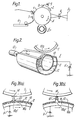
- Fig. 6 is a cross-section perspective view of development apparatus used in a third embodiment of the present invention; and
- Figs. 7(a) and 7(b) are enlarged cross-section views of the development zone in the development apparatus shown in Fig. 6.
- Referring now to Fig. 1, around a photo-sensitive drum 1, a charging device 2, an exposure device 4, a
development apparatus 5, atransfer device 7, cleaning means 8 and a charge remover 9 are disposed sequentially in the order of the electrostatic recording process. The surface of the drum 1 is coated with dielectric material by about 20 µm in thickness, and it is subjected to necessary treatments by these surrounding equipments while the drum 1 is rotated around its center axis in the direction of an arrow A. More particularly, at first, the surface of the photo-sensitive drum 1 is uniformly charged up to about 450 V by the charging device 2 which is a corona discharge generator. Subsequently, an image on an original sheet 3 is focused on the surface of the drum 1 by means of the exposure device 4 to remove the electric charge at light portions of the focused image on the surface of the drum 1. Thereby, a latent electrostatic image of positive electric charge is formed on the surface of the photo-sensitive drum 1. The developer agent is charged negatively in thedevelopment apparatus 5. The electrostatic image makes the developer agent adhere thereto by its electrostatic attractive force, and thus the latent electrostatic image is developed into a visual image. A sheet is fed to thetransfer device 7 from a sheet hopper 6 by means of feed rollers. Thetransfer device 7 charges the fed sheet in a negative polarity. Therefore, the visual image formed on the drum surface is transferred to the sheet by attracting force of the negative charge on the sheet. After the transfer, remaining developer agent on the surface of the drum 1 is removed by the cleaning means 8. Finally, electric charge left on the drum surface is removed by the charge remover 9, and thus the electrostatic recording process is completed. - Referring to Fig. 2, the
development apparatus 5 is mainly composed of an electricallyconductive sleeve 10, anink tank 11 and electricallyconductive ink 12 filled within thetank 11. The electricallyconductive sleeve 10 has a rotary axis in parallel to a photo-sensitive drum 1 and rotates as driven by amotor 13. Thesleeve 10 is opposed to the photo-sensitive drum 1 closely but without making contact therewith. Theink tank 11 is filled up with electricallyconductive ink 12 and thesleeve 10 is submerged in theink 12. - The
sleeve 10 has a hollow inner portion and a large number of minute circular depressions 10a formed on its surface. Thesleeve 10 is a copper pipe formed with depressions on its surface by etching and is given a surface treatment by chromium plating thereafter. The depressions 10a are formed over the entire surface of thesleeve 10 and the density of formation thereof is 200 to 600 depressions per square inch. The depressions 10a are regularly arrayed in a zigzag matrix form, a diameter of a depression is 40 to 70 µm, the distance between the centers of adjacent depressions 10a is 50 to 80 µm, and the depth of a depression 10a is about 10 to 50 µm. - It is to be noted that a sleeve having depressions could, for example, alternatively be produced by coating
the surface of an aluminium pipe with foamed (porous) aluminium instead of by etching a copper pipe. - A negative voltage V, preset at about -20 to -50 V, is applied to the
sleeve 10, so that the ink trapped in the depression 10a by the rotation of thesleeve 10 is charged negatively. By making this voltage variable,theprinting density can be adjusted. - The photo-sensitive drum 1 and the
sleeve 10 are disposed with their side surfaces opposed to each other. The gap distance therebetween at the most close position (development zone) is preset at about 0.3 to 0.5 mm. The photo-sensitive drum 1 and thesleeve 10 rotate in the opposite directions to each other, and a circumferential rotational velocities of thesleeve 10 is preset 3 to 7 times as high as that of the photo-sensitive drum 1. - In the
development apparatus 5, aconductive liquid developer 12, having a viscosity of 5 to 7 cps, a surface tension of 3 to 4 'dyne/cm and a specific resistance of 108 ohm-cm, is employed. These conditions are satisfied by the characteristics of water-soluble and oily ink which are generally and commercially obtained. Accordingly, thedevelopment apparatus 5 does not require a special liquid developer, and for instance, the ink for ink jet printer use, the ink for fountain pen use, or other inks could be used. - When the
sleeve 10 arranged within theink tank 11 is rotated by driving themotor 13, theliquid developer 12 is held within the large number of depressions 10a on the surface of thesleeve 10 and thereby carried to the position (development zone) opposed to the photo-sensitive drum 1. As shown in Fig. 3 which partly shows the photo-sensitive drum 1 and thesleeve 10 at the development zone in an enlarged scale, the photo-sensitive drum 1 formed with a latentelectrostatic image 14 on its surface and thesleeve 10 holding theliquid developer 12 in the depressions 10a are rotated in the opposite directions to each other at predetermined velocities. As shown in Fig. 3(a), theliquid developer 12 is held in the large number of depressions 10a and charged negatively. The latentelectrostatic image 14 formed on the surface of the drum 1 is charged positively. As the latentelectrostatic image 14 is gradually approaching thesleeve 10 by rotating of the drum 1, an electrostatic field between the latentelectrostatic image 14 and the liquid developer 12' held in the depression l0a' which is opposed to the latent image.14 is increasing. Hence, an attractive force towards the photo-sensitive drum 1 is exerted upon the liquid developer 12'. As the drum 1 and thesleeve 10 further rotate, the distance between thelatent image 14 and the liquid developer 12' is further reduced and the attractive force exerted upon the liquid developer 12' is further increased. When the distance between the drum 1 and thesleeve 10 becomes minimum, the attractive force exerted upon the liquid developer 12' by thelatent image 14 becomes maximum. As shown in Fig. 3(b), the liquid developer 12' jumps up in a drop state towards thelatent image 14 at this time,against its viscosity, surface tension and gravitation, and adheres to thelatent image 14 on the drum 1. In this way, theliquid developer 12 jumps up to the latent electrostatic image on the drum 1 in the drop state divided by the depressions 10a, and thereby the latent image is developed into a visual image. - Since the
developer liquid 12 can be reliably held up to the development zone by the depressions 10a on the surface of thesleeve 10, a uniform visual image can be formed on the drum 1. In addition, the depressions 10a are formed on the surface of thesleeve 10 at a high density, and theliauid developer 12 adheres to the latent electrostatic image on the surface of the drum 1 in the drop state divided by the depressions 10a, so that the latent electrostatic image can be precisely developed into a visual image and the obtained visual image has a very high resolution. - Referring now to Fig. 4 showing a development apparatus 5' used in a second embodiment of the present invention, a
cylindrical sleeve 20 is rotatably disposed within anink tank 21. Thesleeve 20 has a large number of micro-fine bores 20a regularly formed in its circumferential wall by a well-known process such as etching. The thickness of thecylindrical sleeve 20 is about 0.1 mm, the distance between the centers of the adjacent bores 20a is 50 to 80 µm, and the diameter of the bore 20a is 40 to 70 µm. - A negative voltage of about -20 to -50 V is applied to the
sleeve 20, and thereby the electricallyconductive liquid developer 22 held in the micro-fine bores 20a is charged negatively. With regard to theliquid developer 22, a similar liquid developer to that used in the first embodiment is used. - The gap between the photo-sensitive drum 1 and the
sleeve 20, their rotational velocities and their directions of rotation are similar to those described above in connection to the first preferred embodiment, and therefore, further description thereof will be omitted. - Referring now to Fig. 5, the photo-sensitive drum 1 and the
sleeve 20 are rotating in the opposite directions to each other in the development zone. As thelatent image 24 on the drum 1 gradually approaches thesleeve 20, an attractive force towards the drum 1 is exerted upon the liquid developer 22' by the electric charge possessed by the latent image 24 (Fig.5(a)). As the drum 1 and thesleeve 20 further rotate, when thelatent image 24 and the developer liquid 22' have approached up to the shortest distance, the liquid developer 22' held in the bore 20a' jumps up in a drop state towards the drum 1 against its viscosity, surface tension and the gravitation, and adheres to the latent image 24 (Fig. 5(b)). - The
liquid developer 22 is carried to the development zone by holding in a large number of micro-fine bores 20a formed in thesleeve 20 and arrayed at a high density, and thedeveloper liquid 22 develops the latent electrostatic image on the drum 1 into a visual image in the drop state divided by the bores 20a. Therefore, a visual image of high quality and high resolution can be formed on the drum 1. - Referring now to Fig. 6 showing a
development apparatus 5" used in a third embodiment of the present invention, a large number of electrically conductive needle-like fine members 30a extend from theface ofacylindrical sleeve 30 made of stainless steel. Thesleeve 30 is provided rotatably within anink tank 31 to form a cylindrical brush. The length of the needle-like fine members 30a is 3 to 5 mm, and it is desirable for themembers 30a to be as dense as possible. As a material for the needle-like fine members 30a, stainless steel or carbon fibers are used. - A negative voltage of about -20 to -50 V is applied to the
sleeve 30, and thereby electricallyconductive developer liquid 32 held around the needle-like fine members 30a is negatively charged. - The photo-sensitive drum 1 and the
sleeve 30 are provided in an opposed relationship to each other, and the gap distance between the surface of the drum 1 and the tip end of the needle-like fine members 30a is appropriately about 0.3 to 1.5 mm. - The various conditions required for the
developer liquid 32, and the rotational velocities and directions of rotation of the drum 1 and thesleeve 30 are similar to those described above in connection to the first preferred embodiment, and therefore, further description thereof will be omitted. - Referring to Fig. 7, in the development zone, the photo- sensitive drum 1 and the
sleeve 30 are rotating in the opposite directions to each other with a certain relative circumferential velocity. As a latentelectrostatic image 34 on the drum 1 gradually approaches thesleeve 30, an attraction force directed towards the drum 1 is exerted upon a developer liquid 32' held by the needle-like fine members 30a' due to the electric charge possessed by the latent image 34 (Fig. 7(a)). As the drum 1 and thesleeve 30 is further rotating, when thelatent image 34 and the liquid developer 32' have approached up to the shortest distance, the liauid developer 32'held by the needle-like fine members 30a' jumps up in a drop state towards the drum 1 against its viscosity, surface tension and the gravitation, and adheres to thelatent image 34. In this way a visual image can be formed on the drum 1 (Fig. 7(b)). - The
developer liquid 32 is reliably carried to the development zone by having the needle-like fine members 30.a placed at a high density on thesleeve 30, and the latent electrostatic image on the drum 1 is developed into a visual image by the drop-state liquid developer divided-up by thefine members 30a. Therefore, a visual image of high quality and high resolution can be obtained on the drum 1. - As described above, it will be seen that a sleeve, having holding means for holding a micro-fine amount of the liquid developer on its outer circumferential surface, is disposed in an opposed relation to a photo- sensitive drum without making contact with it, and both the sleeve and the drum rotate having a relative circumferential velocity. Thereby, a latent electrostatic image formed on on the surface of the photo-sensitive drum can be precisely developed at a high resolution, and as a result, a visual image of high quality can be transferred to a sheet.
- It will be understood that the needle-
like fine members 30a may be formed as studs extending from the surface of thesleeve 30. - It will be appreciated that the depressions 10a and the holes 20a can be arranged in any pattern although in a preferred arrangement they are arranged in a zig-zag matrix form.
Claims (10)
a photo-sensitive drum (1) coated on its surface with dielectric material,
a charger (2) for uniformly charging the surface of said photo-sensitive drum (1);
an exposure device (4 for exposing the surface of said photo-sensitive drum (1) in order to form a latent electrostatic image thereon;
a transfer device (7) for transferring said visual image formed on the surface of said photo-sensitive drum onto a sheet;
a cleaning device (8) for removing liquid developer remaining on the surface of said photo-sensitive drum which has finished said transfer process;
a charge remover (9) for removing electric charge remaining on the surface of said photo-sensitive drum which has finished said transfer process; and
a development apparatus (5) including a tank (11) for accommodating an electrically conductive liquid developer (12), characterised in that an electrically conductive sleeve (10) is disposed rotatably within said tank (11) and that said sleeve (10) has holding means (10a) for said liquid developer formed on its outer circumferential surface, the sleeve 10 being disposed at a predetermined distance from said photo-sensitive drum (1), whereby said latent electrostatic image can be developed into a visual image.
Applications Claiming Priority (6)
| Application Number | Priority Date | Filing Date | Title |
|---|---|---|---|
| JP5699282A JPS58173771A (en) | 1982-04-06 | 1982-04-06 | Developing device |
| JP56992/82 | 1982-04-06 | ||
| JP57058595A JPS58174973A (en) | 1982-04-08 | 1982-04-08 | Developing device |
| JP57058596A JPS58174974A (en) | 1982-04-08 | 1982-04-08 | Developing device |
| JP58596/82 | 1982-04-08 | ||
| JP58595/82 | 1982-04-08 |
Publications (2)
| Publication Number | Publication Date |
|---|---|
| EP0091780A1 true EP0091780A1 (en) | 1983-10-19 |
| EP0091780B1 EP0091780B1 (en) | 1987-02-04 |
Family
ID=27296104
Family Applications (1)
| Application Number | Title | Priority Date | Filing Date |
|---|---|---|---|
| EP83301935A Expired EP0091780B1 (en) | 1982-04-06 | 1983-04-06 | Development apparatus of latent electrostatic images |
Country Status (3)
| Country | Link |
|---|---|
| US (1) | US4493550A (en) |
| EP (1) | EP0091780B1 (en) |
| DE (1) | DE3369751D1 (en) |
Cited By (1)
| Publication number | Priority date | Publication date | Assignee | Title |
|---|---|---|---|---|
| EP0458230A2 (en) * | 1990-05-24 | 1991-11-27 | MAN Roland Druckmaschinen AG | Method and device for toning a printing forme of ferroelectric material |
Families Citing this family (36)
| Publication number | Priority date | Publication date | Assignee | Title |
|---|---|---|---|---|
| US4648704A (en) * | 1985-11-29 | 1987-03-10 | Eastman Kodak Company | Method and apparatus for applying liquid toner to a recording member |
| US4707112A (en) * | 1986-05-16 | 1987-11-17 | Xerox Corporation | Liquid development system |
| JPS6326667A (en) * | 1986-07-18 | 1988-02-04 | Sharp Corp | Development method and device by non-magnetic one-component developer |
| US4982692A (en) * | 1988-02-16 | 1991-01-08 | Nec Corporation | Apparatus for liquid development of electrostatic latent images |
| EP0333199A3 (en) * | 1988-03-17 | 1989-11-29 | Nec Corporation | Liquid development apparatus with perforated liquid carrier sheet |
| EP0352731B1 (en) * | 1988-07-26 | 1994-03-30 | Seiko Epson Corporation | Wet recording apparatus |
| US5253019A (en) * | 1989-10-30 | 1993-10-12 | Xerox Corporation | Developer material transport |
| JP2583661B2 (en) * | 1990-10-26 | 1997-02-19 | 日立金属株式会社 | Magnet roll |
| US5477249A (en) * | 1991-10-17 | 1995-12-19 | Minolta Camera Kabushiki Kaisha | Apparatus and method for forming images by jetting recording liquid onto an image carrier by applying both vibrational energy and electrostatic energy |
| JPH1173023A (en) * | 1997-08-29 | 1999-03-16 | Brother Ind Ltd | Image forming device |
| US5893663A (en) * | 1997-11-19 | 1999-04-13 | Xerox Corporation | Web liquid charging: improved resistance to contamination |
| DE19823468C1 (en) * | 1998-05-26 | 1999-10-28 | Windmoeller & Hoelscher | Digital printing machine |
| JP2000075667A (en) * | 1998-08-28 | 2000-03-14 | Brother Ind Ltd | Image forming device |
| JP2000233501A (en) * | 1999-02-15 | 2000-08-29 | Minolta Co Ltd | Image forming apparatus |
| DE10027173A1 (en) * | 2000-05-31 | 2001-12-13 | Oce Printing Systems Gmbh | Device and method for electrographic printing or copying using liquid colorants |
| KR100547104B1 (en) * | 2002-02-21 | 2006-01-26 | 삼성전자주식회사 | Wet type development unit using high density ink |
| US7925192B2 (en) * | 2007-09-04 | 2011-04-12 | Ricoh Company, Ltd. | Developing roller, developing device, process cartridge, and image forming apparatus |
| CA2753891C (en) * | 2009-03-04 | 2015-01-13 | Xerox Corporation | Structured organic films having an added functionality |
| US8355035B2 (en) * | 2010-01-29 | 2013-01-15 | Palo Alto Research Center Incorporated | Digital gravure printing with a pixilated photoconductor |
| US9567425B2 (en) | 2010-06-15 | 2017-02-14 | Xerox Corporation | Periodic structured organic films |
| US8318892B2 (en) | 2010-07-28 | 2012-11-27 | Xerox Corporation | Capped structured organic film compositions |
| US8697322B2 (en) | 2010-07-28 | 2014-04-15 | Xerox Corporation | Imaging members comprising structured organic films |
| US8257889B2 (en) | 2010-07-28 | 2012-09-04 | Xerox Corporation | Imaging members comprising capped structured organic film compositions |
| US8119315B1 (en) | 2010-08-12 | 2012-02-21 | Xerox Corporation | Imaging members for ink-based digital printing comprising structured organic films |
| US8119314B1 (en) | 2010-08-12 | 2012-02-21 | Xerox Corporation | Imaging devices comprising structured organic films |
| US8759473B2 (en) | 2011-03-08 | 2014-06-24 | Xerox Corporation | High mobility periodic structured organic films |
| US8247142B1 (en) | 2011-06-30 | 2012-08-21 | Xerox Corporation | Fluorinated structured organic film compositions |
| US8353574B1 (en) | 2011-06-30 | 2013-01-15 | Xerox Corporation | Ink jet faceplate coatings comprising structured organic films |
| US8313560B1 (en) | 2011-07-13 | 2012-11-20 | Xerox Corporation | Application of porous structured organic films for gas separation |
| US8377999B2 (en) | 2011-07-13 | 2013-02-19 | Xerox Corporation | Porous structured organic film compositions |
| US8410016B2 (en) | 2011-07-13 | 2013-04-02 | Xerox Corporation | Application of porous structured organic films for gas storage |
| US8372566B1 (en) | 2011-09-27 | 2013-02-12 | Xerox Corporation | Fluorinated structured organic film photoreceptor layers |
| US8460844B2 (en) | 2011-09-27 | 2013-06-11 | Xerox Corporation | Robust photoreceptor surface layer |
| US8529997B2 (en) | 2012-01-17 | 2013-09-10 | Xerox Corporation | Methods for preparing structured organic film micro-features by inkjet printing |
| US8765340B2 (en) | 2012-08-10 | 2014-07-01 | Xerox Corporation | Fluorinated structured organic film photoreceptor layers containing fluorinated secondary components |
| US8906462B2 (en) | 2013-03-14 | 2014-12-09 | Xerox Corporation | Melt formulation process for preparing structured organic films |
Citations (5)
| Publication number | Priority date | Publication date | Assignee | Title |
|---|---|---|---|---|
| DE2056572B2 (en) * | 1969-11-17 | 1974-01-10 | Fuji Photo Film Co. Ltd., Ashigara, Kanagawa (Japan) | Device for applying a liquid to the surface of a web |
| US3980404A (en) * | 1974-07-26 | 1976-09-14 | Xerox Corporation | Xerographic apparatus having improved fluid dispensing member |
| US4202913A (en) * | 1976-04-13 | 1980-05-13 | Philip A. Hunt Chemical Corp. | Method for liquid development of latent electrostatic images |
| DE3006781A1 (en) * | 1979-02-23 | 1980-08-28 | Savin Corp | METHOD AND COPIER FOR DEVELOPING LATEN CHARGE IMAGES |
| GB2046134A (en) * | 1979-04-16 | 1980-11-12 | Hunt Chem Corp Philip A | Development of Electrostatic Images |
Family Cites Families (5)
| Publication number | Priority date | Publication date | Assignee | Title |
|---|---|---|---|---|
| US3232190A (en) * | 1963-06-28 | 1966-02-01 | Ibm | Method and apparatus for copying |
| JPS4960534A (en) * | 1972-10-11 | 1974-06-12 | ||
| GB1429518A (en) * | 1973-09-07 | 1976-03-24 | Xerox Corp | Resilient rollers |
| US3993020A (en) * | 1975-05-16 | 1976-11-23 | Xerox Corporation | Blade applicator assembly |
| US4024838A (en) * | 1976-05-07 | 1977-05-24 | Rank Xerox Ltd. | Developer liquid supplying device |
-
1983
- 1983-04-06 EP EP83301935A patent/EP0091780B1/en not_active Expired
- 1983-04-06 US US06/482,647 patent/US4493550A/en not_active Expired - Lifetime
- 1983-04-06 DE DE8383301935T patent/DE3369751D1/en not_active Expired
Patent Citations (5)
| Publication number | Priority date | Publication date | Assignee | Title |
|---|---|---|---|---|
| DE2056572B2 (en) * | 1969-11-17 | 1974-01-10 | Fuji Photo Film Co. Ltd., Ashigara, Kanagawa (Japan) | Device for applying a liquid to the surface of a web |
| US3980404A (en) * | 1974-07-26 | 1976-09-14 | Xerox Corporation | Xerographic apparatus having improved fluid dispensing member |
| US4202913A (en) * | 1976-04-13 | 1980-05-13 | Philip A. Hunt Chemical Corp. | Method for liquid development of latent electrostatic images |
| DE3006781A1 (en) * | 1979-02-23 | 1980-08-28 | Savin Corp | METHOD AND COPIER FOR DEVELOPING LATEN CHARGE IMAGES |
| GB2046134A (en) * | 1979-04-16 | 1980-11-12 | Hunt Chem Corp Philip A | Development of Electrostatic Images |
Cited By (2)
| Publication number | Priority date | Publication date | Assignee | Title |
|---|---|---|---|---|
| EP0458230A2 (en) * | 1990-05-24 | 1991-11-27 | MAN Roland Druckmaschinen AG | Method and device for toning a printing forme of ferroelectric material |
| EP0458230A3 (en) * | 1990-05-24 | 1993-08-25 | Man Roland Druckmaschinen Ag | Method and device for toning a ferroelectric material with a liquid film |
Also Published As
| Publication number | Publication date |
|---|---|
| EP0091780B1 (en) | 1987-02-04 |
| US4493550A (en) | 1985-01-15 |
| DE3369751D1 (en) | 1987-03-12 |
Similar Documents
| Publication | Publication Date | Title |
|---|---|---|
| US4493550A (en) | Development apparatus of latent electrostatic images | |
| US5339141A (en) | Developing device with a developer carrier capable of forming numerous microfields thereon | |
| US5172169A (en) | Developer carrier of a developing device and a method of producing the same | |
| US5966570A (en) | Image-wise toner layer charging for image development | |
| US7020420B2 (en) | Device and method for electrographically printing or copying using liquid inks | |
| US5592266A (en) | Electrophotographic process cartridge | |
| NZ241243A (en) | Transferring non conductive and non magnetic toner to electrostatic image cylinder | |
| JPH11153906A (en) | Liquid developing device | |
| EP0389229A2 (en) | Image forming apparatus | |
| US4431296A (en) | Developing method and apparatus therefor | |
| US3806355A (en) | Electrostatic printing apparatus and method | |
| GB2065032A (en) | Image recording method and apparatus | |
| GB1599773A (en) | Method and apparatus for developing electrostatic latent images | |
| US5084718A (en) | Wet recording apparatus and wet recording method | |
| GB1596188A (en) | Electrostatic transfer process and apparatus for carrying out the same | |
| US4245023A (en) | Method for the development of electrostatic charge images | |
| US6876833B2 (en) | Device and method for cleaning and for regenerating an image carrier during electrographic printing or copying by using liquid ink | |
| JP3702523B2 (en) | Developing device using liquid developer | |
| US6799009B2 (en) | Applicator element and method for electrographic printing or copying using liquid coloring agents | |
| US5561507A (en) | Apparatus and method for producing an electrostatic image using water-base toner | |
| EP0899623B1 (en) | Image forming apparatus for performing image formation with liquid developer | |
| JPH04506712A (en) | Electrostatic image gravure printing device | |
| US6118970A (en) | Cleaning roller | |
| JP3304650B2 (en) | Liquid developing device | |
| JP2001051511A (en) | Liquid developing unit and recording device |
Legal Events
| Date | Code | Title | Description |
|---|---|---|---|
| PUAI | Public reference made under article 153(3) epc to a published international application that has entered the european phase |
Free format text: ORIGINAL CODE: 0009012 |
|
| AK | Designated contracting states |
Designated state(s): DE FR GB |
|
| 17P | Request for examination filed |
Effective date: 19831107 |
|
| GRAA | (expected) grant |
Free format text: ORIGINAL CODE: 0009210 |
|
| AK | Designated contracting states |
Kind code of ref document: B1 Designated state(s): DE FR GB |
|
| REF | Corresponds to: |
Ref document number: 3369751 Country of ref document: DE Date of ref document: 19870312 |
|
| ET | Fr: translation filed | ||
| PLBE | No opposition filed within time limit |
Free format text: ORIGINAL CODE: 0009261 |
|
| STAA | Information on the status of an ep patent application or granted ep patent |
Free format text: STATUS: NO OPPOSITION FILED WITHIN TIME LIMIT |
|
| 26N | No opposition filed | ||
| PGFP | Annual fee paid to national office [announced via postgrant information from national office to epo] |
Ref country code: FR Payment date: 19970418 Year of fee payment: 15 |
|
| PGFP | Annual fee paid to national office [announced via postgrant information from national office to epo] |
Ref country code: DE Payment date: 19970627 Year of fee payment: 15 |
|
| PGFP | Annual fee paid to national office [announced via postgrant information from national office to epo] |
Ref country code: GB Payment date: 19980327 Year of fee payment: 16 |
|
| PG25 | Lapsed in a contracting state [announced via postgrant information from national office to epo] |
Ref country code: FR Free format text: THE PATENT HAS BEEN ANNULLED BY A DECISION OF A NATIONAL AUTHORITY Effective date: 19980430 |
|
| PG25 | Lapsed in a contracting state [announced via postgrant information from national office to epo] |
Ref country code: DE Free format text: LAPSE BECAUSE OF NON-PAYMENT OF DUE FEES Effective date: 19990202 |
|
| REG | Reference to a national code |
Ref country code: FR Ref legal event code: ST |
|
| PG25 | Lapsed in a contracting state [announced via postgrant information from national office to epo] |
Ref country code: GB Free format text: LAPSE BECAUSE OF NON-PAYMENT OF DUE FEES Effective date: 19990406 |
|
| GBPC | Gb: european patent ceased through non-payment of renewal fee |
Effective date: 19990406 |