EP0091227B1 - Intravenous needle assembly - Google Patents
Intravenous needle assembly Download PDFInfo
- Publication number
- EP0091227B1 EP0091227B1 EP19830301546 EP83301546A EP0091227B1 EP 0091227 B1 EP0091227 B1 EP 0091227B1 EP 19830301546 EP19830301546 EP 19830301546 EP 83301546 A EP83301546 A EP 83301546A EP 0091227 B1 EP0091227 B1 EP 0091227B1
- Authority
- EP
- European Patent Office
- Prior art keywords
- needle
- handle
- body portion
- hub
- thinner
- Prior art date
- Legal status (The legal status is an assumption and is not a legal conclusion. Google has not performed a legal analysis and makes no representation as to the accuracy of the status listed.)
- Expired
Links
Images

Classifications
-
- A—HUMAN NECESSITIES
- A61—MEDICAL OR VETERINARY SCIENCE; HYGIENE
- A61M—DEVICES FOR INTRODUCING MEDIA INTO, OR ONTO, THE BODY; DEVICES FOR TRANSDUCING BODY MEDIA OR FOR TAKING MEDIA FROM THE BODY; DEVICES FOR PRODUCING OR ENDING SLEEP OR STUPOR
- A61M25/00—Catheters; Hollow probes
- A61M25/01—Introducing, guiding, advancing, emplacing or holding catheters
- A61M25/06—Body-piercing guide needles or the like
- A61M25/0612—Devices for protecting the needle; Devices to help insertion of the needle, e.g. wings or holders
- A61M25/0637—Butterfly or winged devices, e.g. for facilitating handling or for attachment to the skin
Definitions
- the present invention relates to an intravenous needle assembly for placing and maintaining an intravascular needle within a vein.
- Intravenous needle assemblies of the general type with which the present invention is concerned are known in the art. Examples of such prior art assemblies are described in, for example, United States Patents Nos. 2725058, 3064648, 3640275, 3537451, 3782383, 4015600, 4198973, 4300553, British Patents Nos. 1257639, 1274179, 1279852, 1459741, European Patent Application No. 0033207 and International Application No. WO 81/01518. A variety of devices are commercially available. However the presently available devices show certain deficiencies and disadvantages. Most prior art devices include a handle comprising a pair of oppositely extending wings connected via a hinge or weakened section to a wing hub which rigidly holds a pointed hollow needle.
- the wings are folded together and grasped by the fingers and thumb.
- the forward pressure applied to the needle to put it through the skin is applied above and behind the needle.
- the material forming the handle is flexible the needle may be easily diverted from its path, for example by tough skin.
- the fingers may slip if the handle is wet or contaminated by lubricant. Such rigid material may also make more difficult the positioning of the point of the needle after it has punctured the skin.
- the present device mitigates this deficiency by producing on the handle of the assembly an insertion aid in the form of a pair of laterally extending horns against which the finger and thumb grasping the handle may apply positive pressure during insertion.
- This provides a rigid handle which is less likely to be diverted by tough skin or to allow the fingers to slip if wet.
- the handle also allows better accuracy when positioning the point of the needle.
- a preferred embodiment in which the wing portions of the handle fit around the body portion when folded further enhances these advantages.
- the assemblies envisaged in a preferred embodiment of the present invention will allow free rotation of the needle and its hub within the body portion of the handle, thereby allowing unblocking of the needle without inconvenience at a reduced risk to the patient. Therefore the intravenous needle assembly of the present invention will improve handling by the physician, facilitate insertion of the needle by ensuring efficient application of applied forces in the intended direction, will sit comfortably on the skin and will in a preferred embodiment enable rotational manipulation of the needle if desired without disturbing the taping site.
- the present invention provides a handle for use in an intravenous needle assembly for placing and maintaining an intravascular needle within a vein which comprises a body portion being connected via hinge portions to oppositely extending wing sections characterised in that the body portion has at its distal end an insertion aid in the form of a pair of laterally extending horns against which pressure may be applied when introducing the point of the needle assembly beneath the skin.
- each horn will extend away from the axis of the needle such that the angle between the direction of each horn and the axis of the needle lies between 20 and 90° and preferably lies between 30 and 60°.
- the length of the horns will depend upon the overall size of the intravenous needle assembly but generally they will be between 1.5 and 10 mm in length, more suitably will be 2.0 to 7.5 mm and preferably will be 2.5 to 5.0 mm in length.
- the horns will be straight or arcuate in shape. Preferably the horns will be straight.
- each wing section of the handle has adjacent to the hinge a thinner portion of such dimension that when the wings are folded, the thinner portion conforms and folds around the body portion in close fit therewith. This provides greater stability to the needle and handle in relation to the forward pressure exerted on them during insertion.
- the thinner portions have on their surface raised areas so that when the wings are folded the raised areas contact the body portion and thereby increase the pressure applied to the walls of the body portion which will cause the needle hub to be gripped more strongly than before when the wings are folded.
- the raised areas will be in the form of a pattern or may be in the form of a single raised line, preferably of triangular cross-section which runs from the front to the back of the handle.
- the raised areas When the raised areas are on a thinner portion of the wing area they will not cover, suitably, more than 50% of this area as this will reduce the flexibility of the thinner area and thereby make manipulation more difficult.
- each thinner area will have a raised line of triangular cross-section which runs from the front to the back of the handle.
- the horns and wings with thinner portions will both be present in the handle. This has the advantage of allowing greater access of the finger and thumb to the horns as the wings are folded out of the way.
- the body portion may be of circular or rectangular, including square, cross-section.
- the body .portion is square in cross-section.
- the wing sections do not interlock or otherwise fit together as is found in several prior art devices, but may touch only at their tips.
- the folding of the wings causes stress in the body portion which results in a temporary distortion in the shape of the body which prevents the needle hub rotating.
- the needle hub is again free to rotate.
- the handle may form an integral part of the intravenous needle assembly, that is the blunt end of the needle may be held rigidly within the handle.
- the handle is adapted to surround a needle hub which rigidly holds the needle in such a manner as to permit free rotation of the needle hub about its axis inside the handle.
- an intravenous needle assembly for placing and maintaining an intravenous needle within a vein which comprises a needle, a hub which rigidly holds the needle and a handle mounted on the hub in a manner which allows free rotation of the needle hub within the handle, said handle comprising a body portion connected via hinge portions to oppositely extending wing sections characterised in that the body portion has at its distal end an insertion aid in the form of a pair of laterally extending horns against which pressure may be applied when introducing the point of the needle beneath the skin.
- the wings of the handle will have adjacent to the hinge thinner portions having dimensions such that when the wings are folded the thinner portion conforms to and folds around the body portion in close fit therewith, thereby preventing rotation of the needle hub within the handle during the process of introducing the point of the needle beneath the skin.
- each of said thinner portions carries a raised area on the surface which in use contacts the body portion when the wings are folded so as to apply pressure to the body portion to prevent rotation of the needle hub when the wings are folded.
- the present invention comprises an intravenous needle assembly comprising a needle and a handle as hereinbefore described wherein the needle is rigidly held in the handle.
- the assembly may advantageously carry a connection tube closed by a luer lock at its distal end at the proximal end of the handle or hub respectively which forms a reusable connection to an extracorporeal blood circuit or source of infusion fluid and the like.
- the handle comprised of the body portion, wing section and insertion aid will be formed as a single unit by injection moulding from a thermoplastic polymer.
- the thermoplastic polymer will be a polyolefin. Suitable polyolefins include high-density and low-density polyethylene and ' polypropylene.
- a preferred polyolefin is polypropylene.
- the polyolefins, and polypropylene in particular, have the advantage of being rigid whilst being capable of forming a hinge portion without becoming brittle on flexing.
- Such polymers will reversibly accept stress which in the preferred embodiment allows the needle hub to be held still during insertion with the wing sections folded whilst allowing free rotation of the needle hub when relaxed.
- the polyolefins are hypoallergenic when used in contact with the skin.
- the polyolefins may be easily colour coded to designate different gauges of needle.
- the pointed needle will be of the type conventionally used for intravenous applications.
- the needles are formed from stainless steel which optionally may be covered by a biocompatible coating to aid performance.
- the outside diameter of the needles will be between 1.5 and 2.0 mm.
- the exposed length of the needle will be between 15 to 35 mm and preferably is 25 to 30 mm.
- the handle is suitably moulded around the blunt end of the needle which has been previously roughened or scored to provide a keying surface.
- the needle may be fixed in a preformed handle by the use of. a suitable adhesive.
- the needle hub will be formed from methacrylate-butadiene-styrene polymer (known as MBS polymer) or acrylonitrile-butadiene-styrene polymer (known as ABS polymer).
- MBS polymer methacrylate-butadiene-styrene polymer
- ABS polymer acrylonitrile-butadiene-styrene polymer
- the ABS or MBS polymer is conventionally moulded around the needle to form the hub.
- the enclosed end of the needle is previously roughened or scored to ensure the needle is held fixedly in the hub.
- the internal bore of the needle and needle hub is arranged to be as smooth as possible to reduce to the minimum the risk of damage to infused fluids, for example, blood.
- the needle hub will have an annular flange close to its distal end.
- the body portion and wing sections are held between this flange and tubing which is sealed around the proximal end of the hub and which connects to the extracorporeal blood circuit or source of fluid to be infused.
- the body portion is free to rotate around the needle hub.
- the tubing is aptly that which is commonly used for administration of fluid to the body.
- the tubing may be a polyvinyl chloride, silicone rubber or polyurethane and the like.
- the tubing is sealed to the needle hub using an adhesive.
- the tubing will carry at its proximal end a means for connection to the source of infusion fluid. Commonly this connector is a female luer.
- the tubing may also carry a pinch clip or Halkey Roberts clamp as a means for shutting off the flow of fluid.
- the preferred intravenous needle assemblies of the present invention may be manufactured by simple assembly of the component parts namely (a) the needle hub is insert moulded around the pointed needle (b) the body portion, wing section and horns are injection moulded as a single component (c) the body portion is placed onto the needle hub and is held against the annular flange (d) the tubing is then sealed onto the proximal end of the needle hub thereby holding the body portion on the needle hub. A protective sleeve is placed over the pointed needle to form an interference fit on the needle hub. The pinch clip and luer connection are fitted to the tubing. The whole assembly may then be sealed into a package and sterilised by exposure to ethylene oxide or gamma-irradiation.
- the intravenous needle assemblies are used in dialysis for the removal and return of the blood to the vein, infusion of other fluids containing nutrients, medicaments and the like.
- the needle is expected to remain within the vein for 4 to 6 hours.
- the intravenous assembly is aptly held in place on the skin using adhesive tape which is placed over the wing portions. Less desirably an adhesive film may be coated on to the lower surface of the wing portions and then covered by a protector strip until the assembly is required to be stuck in place. The protector strip is removed and the wing portions adhered to the skin.
- the needle and needle hub shown in Figure 1 comprises a stainless steel needle (1) having a pointed end, the other end of which is held fixedly in a needle hub (2).
- the distal end (3) of the needle hub is of such dimensions as to form an interference fit outside a needle protector tube (not shown) which protects the needle from contamination prior to use.
- the annular flange (4) provides a stop against which the body portion rests.
- the proximal end of the needle hub (5) is of such dimensions as to fit inside the tubing leading from the source of infusion fluid. This tubing is adhered to the needle hub, it being a further advantage of using polyolefin for the body portion, that the body portion is not affected by the adhesive and mutual rotation of the body portion and needle hub is not impaired.
- the bores of the needle hub and needle are so arranged that a smooth connection is made between the two.
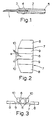
- the second component of the assembly is shown in Figure 2 comprising a body portion (6) having oppositely extending wing sections (7).
- the wing sections (7) are formed with thicker (8) and thinner areas (9) which are shown more clearly in Figure 3.
- the horns (10) are shown extending forward from the wing sections (7) and away from the body portion (6).
- the angle between the direction of the horns (10) and the axis of the needle is shown in this figure as a, and is conventionally 30 to 60°, for example 45°.
- FIG. 3 An end view of the body portion (6), wing section (7) and horns (10) is shown in Figure 3 as viewed from the right hand side of Figure 2.
- the thicker (8) and thinner (9) areas of the wing section are shown.
- the thinner areas (9) being of such dimensions that they will close around the body portion (6) when the wing sections are folded.
- the wing sections fold on a hinge portion (11
- a complete intravenous needle assembly is shown in Figure 4, the needle hub (2) being free to rotate inside the body portion (6).
- the body portion being held in place between the annular flange (4) and the tubing (12) adhered to the proximal end of the needle hub.
- the tubing (12) may carry at its other end a female luer lock connector and centrally on the tubing a pinch clip whereby the flow of infusion fluid may be closed off. It is a considerable advantage in placing the needle if the distal end of the needle hub (3) carries a mark which designates the attitude of the bevel of the pointed needle. This mark may take the form of a coloured dot or indented portion on the needle hub.
- Figure 5 shows an end view of the body portion (6) with the wing sections folded as viewed from the left hand side of Figure 2. This shows how the thinner areas of the wing sections are arranged to close around the square body portion (6) in such a way that there is a gap between the two thicker areas (8) whereby they do not interlock or cooperate with each other in any way.
- the outer surfaces of the thicker areas of the wing sections may carry a raised pattern to assist gripping the wings when folded.
- FIG. 6 An end view of the body portion (6), wing section (7) and horns (10) is shown in Figure 6 in a similar manner to that shown irr Figure 3.
- the thicker (8) and thinner (9) areas of the wing section are shown.
- the thinner areas (9) in this embodiment show a raised portion (13) in the form of a rib which runs along the thinner area of the wing section in a direction parallel to the needle axis.
- the thinner areas (9) being of such dimensions that they will close around the body portion (6) when the wing sections are folded.
- the wing sections fold at a hinge portion (11).
- Figure 7 shows the embodiment of Figure 6 with the wing areas (7) folded around the body portion (6).
- the raised portions (13) provide sufficient pressure against the body portion to prevent rotation of the needle hub during the insertion operation.
- the dimensions of the thinner areas (9) are such that the thicker areas come together as shown on top of the body portion (6).
Description
- The present invention relates to an intravenous needle assembly for placing and maintaining an intravascular needle within a vein.
- Intravenous needle assemblies of the general type with which the present invention is concerned are known in the art. Examples of such prior art assemblies are described in, for example, United States Patents Nos. 2725058, 3064648, 3640275, 3537451, 3782383, 4015600, 4198973, 4300553, British Patents Nos. 1257639, 1274179, 1279852, 1459741, European Patent Application No. 0033207 and International Application No. WO 81/01518. A variety of devices are commercially available. However the presently available devices show certain deficiencies and disadvantages. Most prior art devices include a handle comprising a pair of oppositely extending wings connected via a hinge or weakened section to a wing hub which rigidly holds a pointed hollow needle. To insert the needle into the vein beneath the skin the wings are folded together and grasped by the fingers and thumb. As a result the forward pressure applied to the needle to put it through the skin is applied above and behind the needle. If the material forming the handle is flexible the needle may be easily diverted from its path, for example by tough skin. If the material is rigid the fingers may slip if the handle is wet or contaminated by lubricant. Such rigid material may also make more difficult the positioning of the point of the needle after it has punctured the skin. The present device mitigates this deficiency by producing on the handle of the assembly an insertion aid in the form of a pair of laterally extending horns against which the finger and thumb grasping the handle may apply positive pressure during insertion. This provides a rigid handle which is less likely to be diverted by tough skin or to allow the fingers to slip if wet. The handle also allows better accuracy when positioning the point of the needle. A preferred embodiment in which the wing portions of the handle fit around the body portion when folded further enhances these advantages.
- If the needle when in position should become blocked or lodged with the bevel of the point against the wall of the vein, it is known that mere rotation of the needle within the vein will free the needle from obstruction and restore relatively free flow of fluid. A disadvantage of present devices in which the needle is fixed rigidly to the wing assembly, is that the wing assembly must be untaped or unstuck from the skin, the whole assembly rotated and then retaped or readhered. Even those assemblies which have only a single wing must be untaped and rotated through 180° and then retaped. Such operations may cause unexpected movement which may damage the vein of the patient. The assemblies envisaged in a preferred embodiment of the present invention will allow free rotation of the needle and its hub within the body portion of the handle, thereby allowing unblocking of the needle without inconvenience at a reduced risk to the patient. Therefore the intravenous needle assembly of the present invention will improve handling by the physician, facilitate insertion of the needle by ensuring efficient application of applied forces in the intended direction, will sit comfortably on the skin and will in a preferred embodiment enable rotational manipulation of the needle if desired without disturbing the taping site.
- Accordingly the present invention provides a handle for use in an intravenous needle assembly for placing and maintaining an intravascular needle within a vein which comprises a body portion being connected via hinge portions to oppositely extending wing sections characterised in that the body portion has at its distal end an insertion aid in the form of a pair of laterally extending horns against which pressure may be applied when introducing the point of the needle assembly beneath the skin.
- Suitably each horn will extend away from the axis of the needle such that the angle between the direction of each horn and the axis of the needle lies between 20 and 90° and preferably lies between 30 and 60°.
- The length of the horns will depend upon the overall size of the intravenous needle assembly but generally they will be between 1.5 and 10 mm in length, more suitably will be 2.0 to 7.5 mm and preferably will be 2.5 to 5.0 mm in length.
- Aptly the horns will be straight or arcuate in shape. Preferably the horns will be straight.
- In a second embodiment each wing section of the handle has adjacent to the hinge a thinner portion of such dimension that when the wings are folded, the thinner portion conforms and folds around the body portion in close fit therewith. This provides greater stability to the needle and handle in relation to the forward pressure exerted on them during insertion.
- In a preferred version of this embodiment the thinner portions have on their surface raised areas so that when the wings are folded the raised areas contact the body portion and thereby increase the pressure applied to the walls of the body portion which will cause the needle hub to be gripped more strongly than before when the wings are folded. Suitably the raised areas will be in the form of a pattern or may be in the form of a single raised line, preferably of triangular cross-section which runs from the front to the back of the handle. When the raised areas are on a thinner portion of the wing area they will not cover, suitably, more than 50% of this area as this will reduce the flexibility of the thinner area and thereby make manipulation more difficult. Most preferably each thinner area will have a raised line of triangular cross-section which runs from the front to the back of the handle.
- In a particularly preferred embodiment the horns and wings with thinner portions will both be present in the handle. This has the advantage of allowing greater access of the finger and thumb to the horns as the wings are folded out of the way.
- Suitably the body portion may be of circular or rectangular, including square, cross-section. Preferably the body .portion is square in cross-section.
- When folded the wing sections do not interlock or otherwise fit together as is found in several prior art devices, but may touch only at their tips. In the aspect of the invention in which the needle hub is free to rotate within the body portion, the folding of the wings causes stress in the body portion which results in a temporary distortion in the shape of the body which prevents the needle hub rotating. When the wings are unfolded to their normal flat position the needle hub is again free to rotate.
- From the foregoing it is clear that the handle may form an integral part of the intravenous needle assembly, that is the blunt end of the needle may be held rigidly within the handle. However, in a preferred embodiment the handle is adapted to surround a needle hub which rigidly holds the needle in such a manner as to permit free rotation of the needle hub about its axis inside the handle.
- In a second aspect the present invention provides an intravenous needle assembly for placing and maintaining an intravenous needle within a vein which comprises a needle, a hub which rigidly holds the needle and a handle mounted on the hub in a manner which allows free rotation of the needle hub within the handle, said handle comprising a body portion connected via hinge portions to oppositely extending wing sections characterised in that the body portion has at its distal end an insertion aid in the form of a pair of laterally extending horns against which pressure may be applied when introducing the point of the needle beneath the skin.
- In a preferred embodiment the wings of the handle will have adjacent to the hinge thinner portions having dimensions such that when the wings are folded the thinner portion conforms to and folds around the body portion in close fit therewith, thereby preventing rotation of the needle hub within the handle during the process of introducing the point of the needle beneath the skin.
- In the most preferred embodiment each of said thinner portions carries a raised area on the surface which in use contacts the body portion when the wings are folded so as to apply pressure to the body portion to prevent rotation of the needle hub when the wings are folded.
- In another aspect the present invention comprises an intravenous needle assembly comprising a needle and a handle as hereinbefore described wherein the needle is rigidly held in the handle.
- In either aspect the assembly may advantageously carry a connection tube closed by a luer lock at its distal end at the proximal end of the handle or hub respectively which forms a reusable connection to an extracorporeal blood circuit or source of infusion fluid and the like.
- Generally the handle comprised of the body portion, wing section and insertion aid will be formed as a single unit by injection moulding from a thermoplastic polymer. Aptly the thermoplastic polymer will be a polyolefin. Suitable polyolefins include high-density and low-density polyethylene and 'polypropylene. A preferred polyolefin is polypropylene. The polyolefins, and polypropylene in particular, have the advantage of being rigid whilst being capable of forming a hinge portion without becoming brittle on flexing. Such polymers will reversibly accept stress which in the preferred embodiment allows the needle hub to be held still during insertion with the wing sections folded whilst allowing free rotation of the needle hub when relaxed. The polyolefins are hypoallergenic when used in contact with the skin. The polyolefins may be easily colour coded to designate different gauges of needle.
- In general the pointed needle will be of the type conventionally used for intravenous applications. Suitably the needles are formed from stainless steel which optionally may be covered by a biocompatible coating to aid performance. Most aptly the outside diameter of the needles will be between 1.5 and 2.0 mm. When fixed within the needle hub, the exposed length of the needle will be between 15 to 35 mm and preferably is 25 to 30 mm.
- In the embodiment wherein the needle is held rigidly in the handle, the handle is suitably moulded around the blunt end of the needle which has been previously roughened or scored to provide a keying surface. Alternatively the needle may be fixed in a preformed handle by the use of. a suitable adhesive.
- In the preferred embodiment the needle hub will be formed from methacrylate-butadiene-styrene polymer (known as MBS polymer) or acrylonitrile-butadiene-styrene polymer (known as ABS polymer). The ABS or MBS polymer is conventionally moulded around the needle to form the hub. The enclosed end of the needle is previously roughened or scored to ensure the needle is held fixedly in the hub. The internal bore of the needle and needle hub is arranged to be as smooth as possible to reduce to the minimum the risk of damage to infused fluids, for example, blood.
- Suitably in this preferred embodiment the needle hub will have an annular flange close to its distal end. The body portion and wing sections are held between this flange and tubing which is sealed around the proximal end of the hub and which connects to the extracorporeal blood circuit or source of fluid to be infused. As described hereinbefore the body portion is free to rotate around the needle hub.
- The tubing is aptly that which is commonly used for administration of fluid to the body. Suitably the tubing may be a polyvinyl chloride, silicone rubber or polyurethane and the like. Desirably the tubing is sealed to the needle hub using an adhesive. Conventionally the tubing will carry at its proximal end a means for connection to the source of infusion fluid. Commonly this connector is a female luer..Conventionally the tubing may also carry a pinch clip or Halkey Roberts clamp as a means for shutting off the flow of fluid.
- The preferred intravenous needle assemblies of the present invention may be manufactured by simple assembly of the component parts namely (a) the needle hub is insert moulded around the pointed needle (b) the body portion, wing section and horns are injection moulded as a single component (c) the body portion is placed onto the needle hub and is held against the annular flange (d) the tubing is then sealed onto the proximal end of the needle hub thereby holding the body portion on the needle hub. A protective sleeve is placed over the pointed needle to form an interference fit on the needle hub. The pinch clip and luer connection are fitted to the tubing. The whole assembly may then be sealed into a package and sterilised by exposure to ethylene oxide or gamma-irradiation.
- The intravenous needle assemblies are used in dialysis for the removal and return of the blood to the vein, infusion of other fluids containing nutrients, medicaments and the like. The needle is expected to remain within the vein for 4 to 6 hours. The intravenous assembly is aptly held in place on the skin using adhesive tape which is placed over the wing portions. Less desirably an adhesive film may be coated on to the lower surface of the wing portions and then covered by a protector strip until the assembly is required to be stuck in place. The protector strip is removed and the wing portions adhered to the skin.
- A preferred embodiment of the invention will now be described by way of example only, and with reference to the accompanying drawings wherein:
- Figure 1 is a cross-section of the needle and needle hub.
- Figure 2 is a view from above of the body portion, wing section and horns.
- Figure 3 is an end view looking from the right hand end of Figure 2.
- Figure 4 is a view from above of the complete intravenous needle assembly.
- Figure 5 is an end view of Figure 2 from the left hand end showing the wing sections folded.
- Figure 6 shows an end view of an alternative embodiment of the handle with a raised portion in the thinner area of the wing.
- Figure 7 shows the embodiment of Figure 6 with the wings in the folded position. '
- The needle and needle hub shown in Figure 1 comprises a stainless steel needle (1) having a pointed end, the other end of which is held fixedly in a needle hub (2). The distal end (3) of the needle hub is of such dimensions as to form an interference fit outside a needle protector tube (not shown) which protects the needle from contamination prior to use. The annular flange (4) provides a stop against which the body portion rests. The proximal end of the needle hub (5) is of such dimensions as to fit inside the tubing leading from the source of infusion fluid. This tubing is adhered to the needle hub, it being a further advantage of using polyolefin for the body portion, that the body portion is not affected by the adhesive and mutual rotation of the body portion and needle hub is not impaired. The bores of the needle hub and needle are so arranged that a smooth connection is made between the two.
- The second component of the assembly is shown in Figure 2 comprising a body portion (6) having oppositely extending wing sections (7). The wing sections (7) are formed with thicker (8) and thinner areas (9) which are shown more clearly in Figure 3. The horns (10) are shown extending forward from the wing sections (7) and away from the body portion (6). The angle between the direction of the horns (10) and the axis of the needle is shown in this figure as a, and is conventionally 30 to 60°, for example 45°.
- An end view of the body portion (6), wing section (7) and horns (10) is shown in Figure 3 as viewed from the right hand side of Figure 2. The thicker (8) and thinner (9) areas of the wing section are shown. The thinner areas (9) being of such dimensions that they will close around the body portion (6) when the wing sections are folded. The wing sections fold on a hinge portion (11
- A complete intravenous needle assembly is shown in Figure 4, the needle hub (2) being free to rotate inside the body portion (6). The body portion being held in place between the annular flange (4) and the tubing (12) adhered to the proximal end of the needle hub. The tubing (12) may carry at its other end a female luer lock connector and centrally on the tubing a pinch clip whereby the flow of infusion fluid may be closed off. It is a considerable advantage in placing the needle if the distal end of the needle hub (3) carries a mark which designates the attitude of the bevel of the pointed needle. This mark may take the form of a coloured dot or indented portion on the needle hub.
- Figure 5 shows an end view of the body portion (6) with the wing sections folded as viewed from the left hand side of Figure 2. This shows how the thinner areas of the wing sections are arranged to close around the square body portion (6) in such a way that there is a gap between the two thicker areas (8) whereby they do not interlock or cooperate with each other in any way. Suitably the outer surfaces of the thicker areas of the wing sections may carry a raised pattern to assist gripping the wings when folded.
- An end view of the body portion (6), wing section (7) and horns (10) is shown in Figure 6 in a similar manner to that shown irr Figure 3. The thicker (8) and thinner (9) areas of the wing section are shown. The thinner areas (9) in this embodiment show a raised portion (13) in the form of a rib which runs along the thinner area of the wing section in a direction parallel to the needle axis. The thinner areas (9) being of such dimensions that they will close around the body portion (6) when the wing sections are folded. The wing sections fold at a hinge portion (11).
- Figure 7 shows the embodiment of Figure 6 with the wing areas (7) folded around the body portion (6). The raised portions (13) provide sufficient pressure against the body portion to prevent rotation of the needle hub during the insertion operation. The dimensions of the thinner areas (9) are such that the thicker areas come together as shown on top of the body portion (6).
Claims (9)
Applications Claiming Priority (2)
| Application Number | Priority Date | Filing Date | Title |
|---|---|---|---|
| GB8208578 | 1982-03-24 | ||
| GB8208578 | 1982-03-24 |
Publications (2)
| Publication Number | Publication Date |
|---|---|
| EP0091227A1 EP0091227A1 (en) | 1983-10-12 |
| EP0091227B1 true EP0091227B1 (en) | 1987-10-07 |
Family
ID=10529227
Family Applications (1)
| Application Number | Title | Priority Date | Filing Date |
|---|---|---|---|
| EP19830301546 Expired EP0091227B1 (en) | 1982-03-24 | 1983-03-18 | Intravenous needle assembly |
Country Status (3)
| Country | Link |
|---|---|
| EP (1) | EP0091227B1 (en) |
| JP (1) | JPS58175568A (en) |
| DE (1) | DE3373980D1 (en) |
Families Citing this family (4)
| Publication number | Priority date | Publication date | Assignee | Title |
|---|---|---|---|---|
| DE3600496A1 (en) * | 1986-01-10 | 1987-07-16 | Josef Magasi | TUNING CANNULES, THEIR HANDLE AND METHOD FOR THE PRODUCTION THEREOF |
| JPS6371047U (en) * | 1986-10-30 | 1988-05-12 | ||
| GB9007178D0 (en) * | 1990-03-30 | 1990-05-30 | Smiths Industries Plc | Intravenous needle assemblies |
| CN112807522B (en) * | 2021-03-10 | 2023-05-23 | 山东孟友新材料科技有限责任公司 | Flexible needle tube, preparation method thereof and flexible instillation needle |
Family Cites Families (9)
| Publication number | Priority date | Publication date | Assignee | Title |
|---|---|---|---|---|
| US3537451A (en) * | 1966-10-26 | 1970-11-03 | Deseret Pharma | Intravenous catheter unit with releasable inserter means |
| US3640275A (en) * | 1970-05-05 | 1972-02-08 | Burron Medical Prod Inc | Intravenous needle assembly |
| GB1459741A (en) * | 1972-09-21 | 1976-12-31 | Parkinson P I | Intravenous equipment |
| US4170993A (en) * | 1978-03-13 | 1979-10-16 | Marcial Alvarez | Sliding I.V. needle carrier assembly |
| US4198973A (en) * | 1978-03-14 | 1980-04-22 | Johnson & Johnson | Intravenous catheter assembly with fluid flow restriction capability |
| US4300553A (en) * | 1978-10-12 | 1981-11-17 | Abbott Laboratories | Winged catheter placement assembly |
| US4353369A (en) * | 1980-01-17 | 1982-10-12 | Abbott Laboratories | Venipuncture device |
| AU7485681A (en) * | 1980-10-22 | 1982-04-29 | Travenol European Research And Development Centre | Spike connector |
| JPS646832Y2 (en) * | 1980-10-30 | 1989-02-22 |
-
1983
- 1983-03-18 EP EP19830301546 patent/EP0091227B1/en not_active Expired
- 1983-03-18 DE DE8383301546T patent/DE3373980D1/en not_active Expired
- 1983-03-24 JP JP58049650A patent/JPS58175568A/en active Pending
Also Published As
| Publication number | Publication date |
|---|---|
| EP0091227A1 (en) | 1983-10-12 |
| DE3373980D1 (en) | 1987-11-12 |
| JPS58175568A (en) | 1983-10-14 |
Similar Documents
| Publication | Publication Date | Title |
|---|---|---|
| US4585444A (en) | Intravenous needle assembly | |
| US20230018539A1 (en) | Securement Device Having an Integral Strap and Dressing | |
| US3463152A (en) | Catheter placement unit | |
| EP1285677B1 (en) | Safety shield assembly | |
| US3782383A (en) | Winged infusion holding device with thermoplastic elastomeric body | |
| US3714945A (en) | Digit manipulable quick release cannula insertion device | |
| EP1817068B1 (en) | Multi-position infusion set device and process | |
| JP4279990B2 (en) | Hypodermic needle safety enclosure | |
| US6270480B1 (en) | Catheter apparatus and method | |
| EP1352668B1 (en) | Shielding protection device for needles | |
| US3640275A (en) | Intravenous needle assembly | |
| US4863432A (en) | Winged catheter assembly | |
| ES2214779T3 (en) | NEEDLE PROTECTION ASSEMBLY. | |
| US5135505A (en) | Protective catheter device | |
| US20050101910A1 (en) | Subcutaneous infusion set | |
| US20080319387A1 (en) | Method and Apparatus for Inserting a Catheter Device | |
| WO1981001518A1 (en) | Fitting for use in performing a vascular puncture | |
| WO1996030277A1 (en) | Applicator and method for use in non-contaminating application of a medical catheter | |
| WO2011073916A1 (en) | Disposable shield for a medical tool | |
| US5084032A (en) | Method for using a protective sheath in an intravenous assembly | |
| EP0091227B1 (en) | Intravenous needle assembly | |
| JPS588251B2 (en) | Intravenous catheter assembly | |
| JPH0966106A (en) | Injection needle with needle cover used as fixed wing | |
| EP0261835B2 (en) | Improved winged catheter assembly | |
| CN219630320U (en) | Safety infusion needle for port of infusion port |
Legal Events
| Date | Code | Title | Description |
|---|---|---|---|
| PUAI | Public reference made under article 153(3) epc to a published international application that has entered the european phase |
Free format text: ORIGINAL CODE: 0009012 |
|
| AK | Designated contracting states |
Designated state(s): DE FR GB IT NL |
|
| 17P | Request for examination filed |
Effective date: 19840119 |
|
| GRAA | (expected) grant |
Free format text: ORIGINAL CODE: 0009210 |
|
| AK | Designated contracting states |
Kind code of ref document: B1 Designated state(s): DE FR GB IT NL |
|
| REF | Corresponds to: |
Ref document number: 3373980 Country of ref document: DE Date of ref document: 19871112 |
|
| ITF | It: translation for a ep patent filed |
Owner name: BARZANO' E ZANARDO ROMA S.P.A. |
|
| ET | Fr: translation filed | ||
| PLBE | No opposition filed within time limit |
Free format text: ORIGINAL CODE: 0009261 |
|
| STAA | Information on the status of an ep patent application or granted ep patent |
Free format text: STATUS: NO OPPOSITION FILED WITHIN TIME LIMIT |
|
| 26N | No opposition filed | ||
| PGFP | Annual fee paid to national office [announced via postgrant information from national office to epo] |
Ref country code: FR Payment date: 19900319 Year of fee payment: 8 |
|
| ITTA | It: last paid annual fee | ||
| PGFP | Annual fee paid to national office [announced via postgrant information from national office to epo] |
Ref country code: NL Payment date: 19900331 Year of fee payment: 8 Ref country code: GB Payment date: 19900331 Year of fee payment: 8 |
|
| PGFP | Annual fee paid to national office [announced via postgrant information from national office to epo] |
Ref country code: DE Payment date: 19900430 Year of fee payment: 8 |
|
| PG25 | Lapsed in a contracting state [announced via postgrant information from national office to epo] |
Ref country code: GB Effective date: 19910318 |
|
| PG25 | Lapsed in a contracting state [announced via postgrant information from national office to epo] |
Ref country code: NL Effective date: 19911001 |
|
| GBPC | Gb: european patent ceased through non-payment of renewal fee | ||
| NLV4 | Nl: lapsed or anulled due to non-payment of the annual fee | ||
| PG25 | Lapsed in a contracting state [announced via postgrant information from national office to epo] |
Ref country code: FR Effective date: 19911129 |
|
| PG25 | Lapsed in a contracting state [announced via postgrant information from national office to epo] |
Ref country code: DE Effective date: 19920101 |
|
| REG | Reference to a national code |
Ref country code: FR Ref legal event code: ST |