EP0091098B1 - Flexible magnetic disc drive apparatus - Google Patents
Flexible magnetic disc drive apparatus Download PDFInfo
- Publication number
- EP0091098B1 EP0091098B1 EP83103207A EP83103207A EP0091098B1 EP 0091098 B1 EP0091098 B1 EP 0091098B1 EP 83103207 A EP83103207 A EP 83103207A EP 83103207 A EP83103207 A EP 83103207A EP 0091098 B1 EP0091098 B1 EP 0091098B1
- Authority
- EP
- European Patent Office
- Prior art keywords
- disc
- lever
- door
- clamper
- spindle
- Prior art date
- Legal status (The legal status is an assumption and is not a legal conclusion. Google has not performed a legal analysis and makes no representation as to the accuracy of the status listed.)
- Expired
Links
- 230000002093 peripheral effect Effects 0.000 description 4
- 238000005299 abrasion Methods 0.000 description 2
- 238000006073 displacement reaction Methods 0.000 description 2
- 230000000694 effects Effects 0.000 description 2
- 238000003780 insertion Methods 0.000 description 2
- 230000037431 insertion Effects 0.000 description 2
- 238000005259 measurement Methods 0.000 description 2
- 230000000881 depressing effect Effects 0.000 description 1
- 230000002349 favourable effect Effects 0.000 description 1
- 230000012447 hatching Effects 0.000 description 1
- 238000000034 method Methods 0.000 description 1
- 239000000843 powder Substances 0.000 description 1
- 230000000630 rising effect Effects 0.000 description 1
- 239000013589 supplement Substances 0.000 description 1
Images


Classifications
-
- G—PHYSICS
- G11—INFORMATION STORAGE
- G11B—INFORMATION STORAGE BASED ON RELATIVE MOVEMENT BETWEEN RECORD CARRIER AND TRANSDUCER
- G11B17/00—Guiding record carriers not specifically of filamentary or web form, or of supports therefor
- G11B17/02—Details
- G11B17/022—Positioning or locking of single discs
- G11B17/028—Positioning or locking of single discs of discs rotating during transducing operation
- G11B17/032—Positioning by moving the door or the cover
Definitions
- This invention relates to flexible magnetic disc drive apparatuses.
- Flexible magnetic disc drive apparatuses are now widely accepted.
- This kind of apparatus has a mechanism allowing for the easy exchange of discs.
- This exchange mechanism is actuated interlockingly with a door opened or closed by the operator.
- the inner diameter of the disc is matched with that of a reference hole formed in the spindle and is fitted to the spindle with a prescribed clamping force.
- Such mechanism is known from GB-A-2 002 567 and is indicated in Figs. 1 and 2.
- a disc 10 is clamped between a spindle 12 and clamper 14.
- the clamper 14 is rotatably supported and driven with the spindle 12 without mutual displacement due to a frictional force resulting from an axially- applied load. Even if it is initially inserted off- center from the spindle 12, the center of the disc 10 is eventually rendered concentric with the spindle 12 by the tapered portion of the clamper 14.
- a lever 20 is fitted near the backside 18 of a housing 16 in a state swingable around a pin 22.
- the left front end of said lever 20 is connected to a door 23.
- the lever 20 swings around the pin 22 in accordance with the extent to which the door 23 is operated.
- the clamper 14 is fitted to substantially the midpoint of the lever 20.
- Fig. 2 indicates the relative positions of the clamper 14, the reference hole 24 of the spindle 12 and the disc 10 inserted into the housing 16, showing that the axis of the disc 10 is slightly displaced from that of the reference hole 24 toward the left side.
- the clamper 14 When the disc 10 is fitted to the subject apparatus, the clamper 14 has to be moved to the above-mentioned extent. Since extensive movement of the clamper 14 enlarges the vertical measurement of the subject apparatus, it is preferred that the clamper 14 be moved as little as possible.
- the inclined plane 28 of the clamper 14 was forcefully fitted into the reference hole 24 of the spindle 12 by being moved obliquely down the inner peripheral wall of said reference hole 24. Difficulties were presented in effecting the clamping of the disc 10 and the centering between the disc 10 and spindle 12, and an attempt to minimize the above-mentioned drawbacks was accompanied by various other difficulties as well.
- the object of the present invention is to provide a thin, compact flexible magnetic disc drive apparatus.
- the present invention starts from a flexible magnetic disc drive apparatus according to GB-A-1 596 703.
- such an apparatus is characterized in that said one end of the second lever is connected through a second bearing means to the housing in the vicinity of said clamp assembly, is provided with a projection located between said first bearing means and said disc clamp assembly, and is engageable with said first lever, causing the first lever to be pushed upward by said projection when the other end of the second lever is lifted by the action of the door; said second lever is provided with a spring means engageable with the first lever, and when said other end of the second lever is brought downward by the action of the door, said spring means forces said one end of the first lever downwards towards the spindle in order to center the disc and to elastically hold it between said disc clamper assembly and the spindle.
- the link mechanism of the flexible magnetic disc drive apparatus of this invention is provided with a clamper hanger and door lever.
- the swinging of the door around its axis when it is opened and closed can be carried out to a larger extent than possible with the prior art by means of the lever action of said door lever and clamper hanger, thereby assuring greater movement of the disc clamper assembly.
- a magnetic disc can be smoothly and accurately clamped between the disc damper assembly and spindle without increasing the height of the apparatus.
- reference numeral 40 denotes a disc clamper assembly.
- a clamper 42 supported at the lower end of the disc clamper assembly 40 comprises a hollow conical section 44 provided with a plurality of slits 46. When pushed from the inside, the hollow conical section 44 can be elastically expanded.
- a conical member 48 engageable with the inclined inner wall of the hollow conical section 44 is fitted to a hollow shaft 52 by means of a ball bearing 50.
- the outer end of the hollow shaft 52 is fitted to a housing 54 and is engaged with a guide shaft 56 extending downward substantially concentrical with a spindle 64.
- the hollow shaft 52 can slide vertically together with the ball bearing 50, conical member 48 and clamper 42 (see Figs. 4 and 5).
- the hollow shaft 52 is provided with flanges 58, 60 and is driven by the vertical movement of the outer end portion 63 of the clamper hanger 62, i.e. a first lever projecting into a space defined between the flanges 58, 60.
- the upper end face of the spindle 64 is brought into contact with the underside of the flange 66 provided at one upper end of the clamper 42.
- the hollow conical section 44 of the clamper 42 is elastically expanded by being pushed from the inside by the conical member 48, thereby securely holding the conical member 48.
- the ball bearing 50 is provided between the hollow shaft 52 and conical member 48.
- Reference numeral 70 of Fig. 4 denotes a coil spring.
- a door 80 is supported ahead of a door lever 82, i.e. a second lever, in a state rotatable around a pin 81.
- the door lever 82 extends rearward a little behind the guide shaft 56 of the housing 54 (to the right side of Figs. 4 and 5), and is fitted to the housing 54 by means of a plate spring 84.
- the forward end portion of the door lever 82 is so urged by the plate spring 84 as to be moved upward in the direction of arrow a.
- the left end, that is, the front end of the clamper hanger 62 is fitted to a bracket 86 fixed on the upper wall of the housing 54 close behind the door 80 and door lever 82 in a state rotatable around a .pin 90.
- the door lever 82 comprises a projection 88 protruding from the underside of the door lever 82 such that it passes crosswise underthe clamper hanger 62.
- the door lever 82 is set to be approximately horizontal; and the clamper hanger 62 is pushed upward by the rising of the aforesaid projection 88, and is rotated counterclockwise around the pin 90, causing the disc clamper assembly 40 to be lifted.
- the door lever 82 When the door 80 is closed, that is, when it is in a substantially vertical position, as shown in Fig. 5, the door lever 82 is rotated counterclockwise around its right end supported on the housing 54.
- a plate spring 94 whose right end is fixed by a screw 92 and extends leftward is fitted to the upper side of the door lever 82.
- the left end portion of the plate spring 94 extends over the clamper hanger 62 to push the pressed point 96 of the clamper hanger 62 downward.
- the clamper hanger 62 receives a downward acting force (applied in the direction of arrow b in Fig. 4) at this pressed point 96.
- the clamper hanger 62 is rotated clockwise around the pin 90 by the above-mentioned force.
- the outer end 63 of said clamper hanger 62 pushes the disc clamper assembly 40 downward.
- the disc 68 is clamped between the upper face of the spindle 64 and the flange 66 of the
- a coil spring 100 shown in Figs. 4 and 5 is inserted between the forward portion 57 of the bracket 86 and door lever 82, urging the door lever 82 to rotate clockwise. This urging force supplements the action of the plate spring 84, enabling the door 80 and door lever 82 to be stably operated by the application of a light external force.
- An L-shaped plate spring 102 which is fitted to a projection 82a protruding from the door lever 82 toward the viewer in Fig. 5, extends first horizontally to the right side of the Fig. 5 and then rises upward.
- the door 80 comes to a horizontal position as shown in Fig. 4 by being fully rotated clockwise.
- the door lever 82 swings counterclockwise in the direction of arrow c, as' indicated in Fig. 4, due to the action of the coil spring 100 and plate spring 84, thereby causing the door 80 to be pressed against the guide member 116 and thus be securely held in a horizontal position.
- a sufficiently wide space is formed between the lower end of the clamp member 42 and the upper end face of the spindle 64 to allow for the insertion of the disc 68.
- the door 80 When the disc 68 is fully inserted, the door 80 is rotated counterclockwise- due to its lower end being pushed in the direction of arrow d (indicated in Fig. 4). The upper end of the door 80 is moved leftward along the guide member 116. The door-pivoting pin 81 is moved downward, causing the door lever 82 to swing in the direction of arrow b (in Fig. 4) in which the forward end of the door lever 82 is brought downward.
- the projection 88 of the door lever 82 is released downward from the clamper hanger 62, causing the clamper hanger 62 to be rotated clockwise around the pin 90 by the force of the plate spring 94 fitted to the door lever 82, and consequently, causing the forward end of the clamper hanger 62 to be brought downward.
- the clamper hanger 62 presses the hollow shaft 52 downward, causing the disc clamper assembly 40 to be moved straight toward the spindle 64 along the guide shaft 56.
- the clamper hanger 62 acts as a lever which rotates around the pin 90 with a force applied to the pressed point 96 of said clamper hanger 62.
- the disc clamper assembly 40 is moved to a greater extent than the pressed point 96.
- the above-mentioned movement of the disc clamper assembly 40 causes the conical- section 44 of the clamp member 42 to push the edge of the central hole of the disc 68.
- the disc 68 is moved concentrically with the spindle 64.
- the movement of the disc 68 continues until, as shown in Fig. 5, the conical section 44 of the clamper member 42 is received in the reference hole 67 (Fig. 4) of the spindle 64. At this time, the disc 68 is approximately fixed iri place.
- the door 80 is further rotated, causing the pin 81 to be brought further downward and, consequently, the forward end of the door lever 82 to swing further downward in the direction of arrow b.
- This swinging causes the plate spring 94 fitted to the door lever 82 to apply a downward-acting force to the pressed point 96 of the clamper hanger 62, thereby effecting the depression of the disc clamper assembly 40.
- This depressing force is transmitted to the spindle 64 through the disc 68.
- the disc 68 is tightly held between the disc clamper assembly 40 and spindle 64 concentric with said spindle 64.
- the force applied to the door 80 is also transmitted to the clamper hanger 62 by means of the plate spring 94 to ensure the complete closure of the door 80.
- the above-mentioned force causes the disc 68 to be tightly held between the spindle 64 and disc clamper assembly 40. Consequently, no excess force is applied to the peripheral edge of the central hole of the disc 68 in the process of being centered, nor is the edge subject to abrasion or chipping. After being completely centered, therefore, the disc 68 is advantageously held with a great force.
- the magnetic disc drive apparatus is provided with a mechanism which keeps the door 80 in an open or closed state as need demands. No description is given of this mechanism, as 'it is already well known and falls outside the object and scope of this invention.
- the aforementioned lock mechanism (not shown) is first released to open the door 80. To this end, it is advisable to move the lower end of the door 80 in the direction of arrow e indicated in Fig. 5. Since the door 80 is pushed upward by means of the coil spring (not shown), the upper end of the door is shifted rightward while being guided by the guide member 116. The door 80 is moved upward as a whole, while being rotated around the pin 81. As a result, the door lever 82 is rotated in the counterclockwise direction in Fig. 4 by the action of the coil spring 100 and plate spring 84.
- the clamper hanger 62 is pushed upward by means of the projection 88, and the disc clamper assembly 40 is moved above the spindle 64. Since the displacement of the door lever 82 is effected to a great extent by the clamper hanger 62 acting as a lever, the disc clamper assembly 40 can move through a sufficient long distance.
- the movement of the door-pivoting pin 81 is transmitted to the pressed point 96 of the clamper hanger 62 by the action of the projection 88 of the door lever 82, acting as a lever.
- the movement of the pressed point 96 is transmitted to the disc clamper assembly 40 through the forward end 63 of the. clamper hanger 62 acting as a lever pivoted by the pin 90.
- the conventional magnetic disc drive apparatus of Fig. 1 is so arranged that the clamper 14 is vertically moved by converting the rotation of the door into the movement of an engagement point 25 between a lever pivoted by the pin 22 and clamper 14.
- the conventional disc drive apparatus is so designed as to restrict the movement of a lever.
- the disc drive apparatus of the present invention comprises a link mechanism 38 provided with two levers. One of the two levers restricts the movement of the door to an extent of whereas the other lever enlarges the restricted movement of one lever to an extent of
- Such an enlarged movement of the disc clamper assembly 40 offers the advantages that it is possible to reduce the inclination angle (corresponding to the angle 8 of Fig. 2) of the conical section 44 of the clamper member 42 used to locate the disc 68, to prevent an excess force from being applied to said disc 68 and, consequently, to assure its precise centering.
- the lever extends along substantially the whole length of the apparatus, imposing limitations on the area in which other members are arranged.
- the first and second levels of the disc drive apparatus of this invention extend from the door 80 to a point only a little beyond the center of the spindle 64, that is, the guide shaft 56. Therefore, a large space is left for use in a region defined between the guide shaft 56 and the upper right side thereof indicated in Fig. 4. Consequently, the proper utilization of said space can contribute to the miniaturization of the disc drive apparatus.
- the inclined door lever 82 has about half the length of that of the conventional disc drive apparatus, and its vertical length can be more reduced than in the prior art.
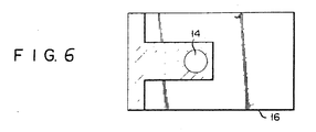
- Fig. 6 is a hatched plan view of the area of the disc drive apparatus of Fig. 4 where the door and link mechanism are arranged, showing that said area is far smaller than in the conventional disc drive apparatus of Fig. 3.
- the disc clamper assembly 40 for holding the disc 68 is arranged concentrically with the spindle 64 to be moved axially therewith offering the advantage of enabling the disc clamper assembly 40 to be smoothly engaged with the spindle 64.
Landscapes
- Holding Or Fastening Of Disk On Rotational Shaft (AREA)
Description
- This invention relates to flexible magnetic disc drive apparatuses. Flexible magnetic disc drive apparatuses are now widely accepted. This kind of apparatus has a mechanism allowing for the easy exchange of discs. This exchange mechanism is actuated interlockingly with a door opened or closed by the operator. The inner diameter of the disc is matched with that of a reference hole formed in the spindle and is fitted to the spindle with a prescribed clamping force. Such mechanism is known from GB-A-2 002 567 and is indicated in Figs. 1 and 2. As shown in both figures, a
disc 10 is clamped between aspindle 12 andclamper 14. Theclamper 14 is rotatably supported and driven with thespindle 12 without mutual displacement due to a frictional force resulting from an axially- applied load. Even if it is initially inserted off- center from thespindle 12, the center of thedisc 10 is eventually rendered concentric with thespindle 12 by the tapered portion of theclamper 14. Alever 20 is fitted near thebackside 18 of ahousing 16 in a state swingable around apin 22. The left front end of saidlever 20 is connected to adoor 23. Thelever 20 swings around thepin 22 in accordance with the extent to which thedoor 23 is operated. Theclamper 14 is fitted to substantially the midpoint of thelever 20. When moved downward by the swinging of the lever, theclamper 14 is fitted into thereference hole 24 formed in thespindle 12. Fig. 2 indicates the relative positions of theclamper 14, thereference hole 24 of thespindle 12 and thedisc 10 inserted into thehousing 16, showing that the axis of thedisc 10 is slightly displaced from that of thereference hole 24 toward the left side. - Description will now be given of the operation of the conventional flexible magnetic disc drive apparatus. When the
door 23 is closed by means of the swinging of thelever 20, then thedisc 10 is pushed rightward by the conical inclined plane 28 (with an indicated angle of inclination 6) formed in the lower part of theclamper 14, causing the center of thedisc 10 to be aligned with that of thespindle 12. When theclamper 14 is moved further downward, thedisc 10 is clamped between theclamper 14 andspindle 12. The total extent to which theclamper 14 is moved during. the above-mentioned operation is equal to the sum of its movement for effecting centering between thedisc 10 andspindle 12 by means of the descent of theinclined plane 28 and its subsequent movement for ensuring the tight clamping of thedisc 10. When thedisc 10 is fitted to the subject apparatus, theclamper 14 has to be moved to the above-mentioned extent. Since extensive movement of theclamper 14 enlarges the vertical measurement of the subject apparatus, it is preferred that theclamper 14 be moved as little as possible. - A flexible magnetic disc drive apparatus of the above-mentioned type is now widely accepted. Recently, however, both computers and their supporting hardware have been greatly reduced in size, and so the need to develop a thin and compact flexible magnetic disc drive apparatus has grown. When the industry sought to meet the above-mentioned requirements simply by miniaturizing the conventional magnetic disc drive apparatus of the aforementioned arrangement, the following drawbacks resulted. Since the
clamper 14 had to be moved to a smaller extent, the inclination angle 8 shown in Fig. 2 had to be enlarged, resulting in an inaccurate centering between thedisc 10 andspindle 12; the edge of the central hole of thedisc 10 also tended to be easily damaged; and since the space between theclamper 14 andspindle 12 was narrowed, thedisc 10 readily struck against the outer end of theclamper 14. In addition, since a distance n (Fig. 1) between thepin 22 supporting thelever 20 and the point at which theclamper 14 was set in place was narrowed, theclamper 14 descended not linearly, but arcuately around the periphery of an imaginary circle centered at thepin 22. - The
inclined plane 28 of theclamper 14 was forcefully fitted into thereference hole 24 of thespindle 12 by being moved obliquely down the inner peripheral wall of saidreference hole 24. Difficulties were presented in effecting the clamping of thedisc 10 and the centering between thedisc 10 andspindle 12, and an attempt to minimize the above-mentioned drawbacks was accompanied by various other difficulties as well. - Studies were made to develop a new magnetic disc drive apparatus in order to eliminate the afore-mentioned drawbacks. With the magnetic disc drive apparatus, shown in Figures 1 and 2, the
lever 20 extends fully from the front end to the rear end of.thehousing 16 along the central line of a space provided above thehousing 16. Noticeable limitations are imposed on the arrangement of devices and members devised for any of the proposed magnetic disc drive apparatus. The hatching of Fig. 3 indicates the approximate area 23a and 20a occupied by thedoor 23 andlever 20 as viewed from the top of the conventional flexible magnetic disc apparatus. It can be seen from Fig. 3 that the hatched area is quite large. - There is also known from GB-A-1 596703 a flexible magnetic disc drive apparatus comprising:
- a door;
- a rotatable spindle;
- a disc clamper assembly which rotatably holds a flexible magnetic disc between said spindle and said disc clamper assembly when said spindle is pushed by said disc clamper assembly;
- a link mechanism for effecting an interlocking operation between the door and the disc clamper assembly and causing the disc to be held by said disc clamper assembly in accordance with the extent to which the door is moved, said link mechanism being provided with a clamp hanger used as a first lever and a door lever used as a second lever; and
- a housing for receiving the door, disc clamper assembly and the link mechanism,
- said first lever being engaged at one end with said disc clamper assembly and being rotatably fitted at the other end of-the--first lever faces the inner surface of the door, said other end of the first lever being fitted to the housing through a first bearing means attached to the housing and located between the disc clamp assembly and the door,
- said second lever being rotatably fitted at one end to the housing and being connected at the other end to the door.
- Also this known apparatus as the apparatus according to GB-A-2 002 567 has a considerable height. This constitutes a disadvantage considering that in many cases flexible magnetic disc drive apparatuses of the type in question are combined with other apparatuses. Therefore there is a need for a flexible magnetic disc drive apparatus having particularly small height.
- Accordingly the object of the present invention is to provide a thin, compact flexible magnetic disc drive apparatus.
- To attain this object, the present invention starts from a flexible magnetic disc drive apparatus according to GB-A-1 596 703. According to the present invention such an apparatus is characterized in that said one end of the second lever is connected through a second bearing means to the housing in the vicinity of said clamp assembly, is provided with a projection located between said first bearing means and said disc clamp assembly, and is engageable with said first lever, causing the first lever to be pushed upward by said projection when the other end of the second lever is lifted by the action of the door; said second lever is provided with a spring means engageable with the first lever, and when said other end of the second lever is brought downward by the action of the door, said spring means forces said one end of the first lever downwards towards the spindle in order to center the disc and to elastically hold it between said disc clamper assembly and the spindle.
- As described above, the link mechanism of the flexible magnetic disc drive apparatus of this invention is provided with a clamper hanger and door lever. The swinging of the door around its axis when it is opened and closed can be carried out to a larger extent than possible with the prior art by means of the lever action of said door lever and clamper hanger, thereby assuring greater movement of the disc clamper assembly. As a result, a magnetic disc can be smoothly and accurately clamped between the disc damper assembly and spindle without increasing the height of the apparatus.
- This invention can be more fully understood from the following detailed description when taken in conjunction with the accompanying drawings, in which:
- Fig. 1 is a front view of the conventional flexible magnetic disc drive apparatus;
- Fig. 2 is a front view of the disc clamper used with the disc drive apparatus of Fig. 1;
- Fig. 3 is a plan view showing the approximate area occupied by the door and link mechanism;
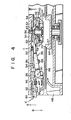
- Fig. 4 is a fragmentary sectional front view of the opened state of the door of a magnetic disc drive apparatus embodying this invention;
- Fig. 5 is a fragmentary sectional front view of the closed state of the door of the magnetic disc drive apparatus of Fig. 4;
- Fig. 6 is plan view showing an approximate area occupied by the door and link mechanism used with the magnetic disc drive apparatus of Fig. 4 as viewed from the top.
- Description will now be given with reference to Figs. 4 and 4 of a flexible magnetic disc drive apparatus embodying this invention. Throughout Figures 4 and 5,
reference numeral 40 denotes a disc clamper assembly. A clamper 42 supported at the lower end of thedisc clamper assembly 40 comprises a hollow conical section 44 provided with a plurality of slits 46. When pushed from the inside, the hollow conical section 44 can be elastically expanded. Inside the clamper 42, aconical member 48 engageable with the inclined inner wall of the hollow conical section 44 is fitted to a hollow shaft 52 by means of a ball bearing 50. The outer end of the hollow shaft 52 is fitted to ahousing 54 and is engaged with aguide shaft 56 extending downward substantially concentrical with aspindle 64. The hollow shaft 52 can slide vertically together with the ball bearing 50,conical member 48 and clamper 42 (see Figs. 4 and 5). The hollow shaft 52 is provided withflanges outer end portion 63 of theclamper hanger 62, i.e. a first lever projecting into a space defined between theflanges spindle 64 is brought into contact with the underside of the flange 66 provided at one upper end of the clamper 42. When the hollow shaft 52 is pulled downward, the hollow conical section 44 of the clamper 42 is elastically expanded by being pushed from the inside by theconical member 48, thereby securely holding theconical member 48. The ball bearing 50 is provided between the hollow shaft 52 andconical member 48. Thus, even while thedisc clamper assembly 40 andspindle 64, and thedisc 68 clamped therebetween are rotated, theouter end 63 of theclamper hanger 62 and hollow shaft 52 are engaged with each other without mutual sliding, thereby suppressing the occurrence of abrasion and the resultant powders therebetween.Reference numeral 70 of Fig. 4 denotes a coil spring. When thedisc clamper assembly 40 is positioned above thespindle 64, saidcoil spring 70 renders both members concentric with each other. Further, when the clamping member 42 fails to assure a concentric relationship between thedisc 68 andspindle 64, then saidcoil spring 70 serves to cushion the movement of thedisc 68. - Referring to Figs. 4 and 5, a
door 80 is supported ahead of adoor lever 82, i.e. a second lever, in a state rotatable around apin 81. Thedoor lever 82 extends rearward a little behind theguide shaft 56 of the housing 54 (to the right side of Figs. 4 and 5), and is fitted to thehousing 54 by means of a plate spring 84. The forward end portion of thedoor lever 82 is so urged by the plate spring 84 as to be moved upward in the direction of arrow a. The left end, that is, the front end of theclamper hanger 62 is fitted to abracket 86 fixed on the upper wall of thehousing 54 close behind thedoor 80 anddoor lever 82 in a state rotatable around a .pin 90. Thedoor lever 82 comprises aprojection 88 protruding from the underside of thedoor lever 82 such that it passes crosswise underthe clamperhanger 62. When thedoor 80 is in a substantially horizontal position, as shown in Fig. 4, thedoor lever 82 is set to be approximately horizontal; and theclamper hanger 62 is pushed upward by the rising of theaforesaid projection 88, and is rotated counterclockwise around thepin 90, causing thedisc clamper assembly 40 to be lifted. When thedoor 80 is closed, that is, when it is in a substantially vertical position, as shown in Fig. 5, thedoor lever 82 is rotated counterclockwise around its right end supported on thehousing 54. Aplate spring 94 whose right end is fixed by ascrew 92 and extends leftward is fitted to the upper side of thedoor lever 82. The left end portion of theplate spring 94 extends over theclamper hanger 62 to push the pressedpoint 96 of theclamper hanger 62 downward. As a result, theclamper hanger 62 receives a downward acting force (applied in the direction of arrow b in Fig. 4) at this pressedpoint 96. Theclamper hanger 62 is rotated clockwise around thepin 90 by the above-mentioned force. Theouter end 63 of saidclamper hanger 62 pushes thedisc clamper assembly 40 downward. Thedisc 68 is clamped between the upper face of thespindle 64 and the flange 66 of the clamp member 42. - A coil spring 100 shown in Figs. 4 and 5 is inserted between the
forward portion 57 of thebracket 86 anddoor lever 82, urging thedoor lever 82 to rotate clockwise. This urging force supplements the action of the plate spring 84, enabling thedoor 80 anddoor lever 82 to be stably operated by the application of a light external force. An L-shaped plate spring 102, which is fitted to a projection 82a protruding from thedoor lever 82 toward the viewer in Fig. 5, extends first horizontally to the right side of the Fig. 5 and then rises upward. - When a flexible magnetic disc drive apparatus embodying the invention is opened to allow for the insertion of the
disc 68 into the magnetic disc drive apparatus, thedoor 80 comes to a horizontal position as shown in Fig. 4 by being fully rotated clockwise. In this case, thedoor lever 82 swings counterclockwise in the direction of arrow c, as' indicated in Fig. 4, due to the action of the coil spring 100 and plate spring 84, thereby causing thedoor 80 to be pressed against theguide member 116 and thus be securely held in a horizontal position. At this time, a sufficiently wide space is formed between the lower end of the clamp member 42 and the upper end face of thespindle 64 to allow for the insertion of thedisc 68. When thedisc 68 is fully inserted, thedoor 80 is rotated counterclockwise- due to its lower end being pushed in the direction of arrow d (indicated in Fig. 4). The upper end of thedoor 80 is moved leftward along theguide member 116. The door-pivotingpin 81 is moved downward, causing thedoor lever 82 to swing in the direction of arrow b (in Fig. 4) in which the forward end of thedoor lever 82 is brought downward. As a result, theprojection 88 of thedoor lever 82 is released downward from theclamper hanger 62, causing theclamper hanger 62 to be rotated clockwise around thepin 90 by the force of theplate spring 94 fitted to thedoor lever 82, and consequently, causing the forward end of theclamper hanger 62 to be brought downward. Accordingly, theclamper hanger 62 presses the hollow shaft 52 downward, causing thedisc clamper assembly 40 to be moved straight toward thespindle 64 along theguide shaft 56. At this time, theclamper hanger 62 acts as a lever which rotates around thepin 90 with a force applied to the pressedpoint 96 of saidclamper hanger 62. Therefore, thedisc clamper assembly 40 is moved to a greater extent than the pressedpoint 96. When thedisc 68 is not brought to a concentric state with thespindle 64, the above-mentioned movement of thedisc clamper assembly 40 causes the conical- section 44 of the clamp member 42 to push the edge of the central hole of thedisc 68. As a result, thedisc 68 is moved concentrically with thespindle 64. The movement of thedisc 68 continues until, as shown in Fig. 5, the conical section 44 of the clamper member 42 is received in the reference hole 67 (Fig. 4) of thespindle 64. At this time, thedisc 68 is approximately fixed iri place. When thedisc clamper assembly 40 is further pressed downward, the underside of the flange 66 of the clamp member 42 contacts the peripheral edge of the central hole of thedisc 68, thereby stopping the descent of thedisc clamper assembly 40. When theconical member 48 and the conical section of the clamper member 42 which are provided with a plurality of slits 46 are forcefully expanded to be brought into contact with the inner peripheral wall of thereference hole 67, thedisc 68 is finally fixed in place. Under this condition, thespindle 64, clamp member 42 andconical member 48 are all joined together, thereby stopping the movement of thedisc clamper assembly 40, and consequently, the rotation of theclamper hanger 62 around thepin 90. After the above-mentioned operation, thedoor 80 is further rotated, causing thepin 81 to be brought further downward and, consequently, the forward end of thedoor lever 82 to swing further downward in the direction of arrow b. This swinging causes theplate spring 94 fitted to thedoor lever 82 to apply a downward-acting force to the pressedpoint 96 of theclamper hanger 62, thereby effecting the depression of thedisc clamper assembly 40. This depressing force is transmitted to thespindle 64 through thedisc 68. As a result, thedisc 68 is tightly held between thedisc clamper assembly 40 andspindle 64 concentric with saidspindle 64. - With the magnetic disc drive apparatus of this invention arranged as described above, only a small force is applied to counteract the movement of the
disc clamper assembly 40, until thedisc 68 is finally fixed in place. Since thedisc 68 itself can move freely, only a small force has to be applied to thedisc clamper assembly 40 to effect centering between thedisc 68 and theguide shaft 56, thereby preventing an unduly great force from being applied to thedisc 68. After the above-mentioned centering is brought to an end, a sufficient force is applied to thedoor 80 to effect its complete closure. Since, at this time, thedisc clamper assembly 40 is already pressed against thespindle 64 through thedisc 68, the force applied to thedoor 80 is also transmitted to theclamper hanger 62 by means of theplate spring 94 to ensure the complete closure of thedoor 80. The above-mentioned force causes thedisc 68 to be tightly held between thespindle 64 anddisc clamper assembly 40. Consequently, no excess force is applied to the peripheral edge of the central hole of thedisc 68 in the process of being centered, nor is the edge subject to abrasion or chipping. After being completely centered, therefore, thedisc 68 is advantageously held with a great force. - The magnetic disc drive apparatus is provided with a mechanism which keeps the
door 80 in an open or closed state as need demands. No description is given of this mechanism, as 'it is already well known and falls outside the object and scope of this invention. - When the
disc 68 is taken out of the subject apparatus, the aforementioned lock mechanism (not shown) is first released to open thedoor 80. To this end, it is advisable to move the lower end of thedoor 80 in the direction of arrow e indicated in Fig. 5. Since thedoor 80 is pushed upward by means of the coil spring (not shown), the upper end of the door is shifted rightward while being guided by theguide member 116. Thedoor 80 is moved upward as a whole, while being rotated around thepin 81. As a result, thedoor lever 82 is rotated in the counterclockwise direction in Fig. 4 by the action of the coil spring 100 and plate spring 84. As a result, theclamper hanger 62 is pushed upward by means of theprojection 88, and thedisc clamper assembly 40 is moved above thespindle 64. Since the displacement of thedoor lever 82 is effected to a great extent by theclamper hanger 62 acting as a lever, thedisc clamper assembly 40 can move through a sufficient long distance. - As described above, the movement of the door-pivoting
pin 81 is transmitted to the pressedpoint 96 of theclamper hanger 62 by the action of theprojection 88 of thedoor lever 82, acting as a lever. - As already described, the movement of the pressed
point 96 is transmitted to thedisc clamper assembly 40 through theforward end 63 of the.clamper hanger 62 acting as a lever pivoted by thepin 90. In contrast, the conventional magnetic disc drive apparatus of Fig. 1 is so arranged that theclamper 14 is vertically moved by converting the rotation of the door into the movement of anengagement point 25 between a lever pivoted by thepin 22 andclamper 14. - Comparison will now be made between the magnetic disc drive apparatus of the prior art according to Figures 1 to 3 and that of the present invention. Now let it be assumed in the conventional magnetic disc drive apparatus that m denotes a distance between the
pin 21 pivoting thedoor 23 and thepin 22 pivoting thelever 20; and n represents a distance between theengagement point 25 of thelever 20 with theclamper 14 and theaforesaid pin 22. Then the ratio between the extent of movement of theengagement point 25 and that of thepin 21 of thedoor 23 is equal to the ratio between the lengths m and n given in Fig. 1 (that is n/m=0.62). The value of this ratio, that is, 0.62 was arrived at by the actual measurement of the numerator n (=87 mm) and that of the denominator m (=140 mm). The lengths p and q of the door lever 82 (first lever) shown in Fig. 5 are, respectively, =85 mm and =49 mm. The lengths s and t of the clamper hanger 62 (second lever) shown in Fig. 5 are, respectively, =51 mm and =12 mm. When the principle of the lever is applied, the ratio which the extent of the movement of thepin 81 of thedoor 80 bears to that of the disc clamper.assembly 40 is expressed as:
disc clamper assembly 40 of the conventional disc drive apparatus shown in Fig. 1 is moved to an extent equal to 0.62 that of the above-mentioned upward movement of the door-pivoting pin, whereas thedisc clamper assembly 40 of the present disc drive apparatus shown in Fig. 4 is moved to an extent equal to 2.5 times that of the afore-mentioned upward movement of the door-pivoting pin. The reason why the present invention has achieved such a favorable result is as foHows. - The conventional disc drive apparatus is so designed as to restrict the movement of a lever. In contrast, the disc drive apparatus of the present invention comprises a
link mechanism 38 provided with two levers. One of the two levers restricts the movement of the door to an extent of

disc clamper assembly 40 offers the advantages that it is possible to reduce the inclination angle (corresponding to the angle 8 of Fig. 2) of the conical section 44 of the clamper member 42 used to locate thedisc 68, to prevent an excess force from being applied to saiddisc 68 and, consequently, to assure its precise centering. With the conventional disc drive apparatus mentioned above, the lever extends along substantially the whole length of the apparatus, imposing limitations on the area in which other members are arranged. In contrast, the first and second levels of the disc drive apparatus of this invention extend from thedoor 80 to a point only a little beyond the center of thespindle 64, that is, theguide shaft 56. Therefore, a large space is left for use in a region defined between theguide shaft 56 and the upper right side thereof indicated in Fig. 4. Consequently, the proper utilization of said space can contribute to the miniaturization of the disc drive apparatus. With the disc drive apparatus of the present invention, theinclined door lever 82 has about half the length of that of the conventional disc drive apparatus, and its vertical length can be more reduced than in the prior art. - Fig. 6 is a hatched plan view of the area of the disc drive apparatus of Fig. 4 where the door and link mechanism are arranged, showing that said area is far smaller than in the conventional disc drive apparatus of Fig. 3.
- With the disc drive apparatus of this invention, the
disc clamper assembly 40 for holding thedisc 68 is arranged concentrically with thespindle 64 to be moved axially therewith offering the advantage of enabling thedisc clamper assembly 40 to be smoothly engaged with thespindle 64.
Claims (1)
- A flexible. magnetic disc drive apparatus which comprises:a door (80);a rotatable spindle (64);a disc clamper assembly (40) which rotatably holds a flexible magnetic disc (68) between said spindle (64) and said disc clamper assembly (40) when said spindle (64) is pushed by said disc clamper assembly (40);a link mechanism (38) for effecting an interlocking operation between the door (80) and the disc clamper assembly (40) and causing the disc (68) to be held by said disc clamper assembly (40) in accordance with the extent to which the door (80) is moved, said link mechanism (38) being provided with a clamp hanger (62) used as a first lever and a door lever (82) used as a second lever; anda housing (54) for receiving the door (80), disc clamper assembly (40) and the link mechanism (38), said first lever (62) being engaged at one end with said disc clamper assembly (40) and being rotatably fitted at the other end to the housing (54) in such a way that said other end of the first lever (62) faces the inner surface of the door (80), said other end of the first lever (62) being fitted to the housing through a first bearing means (86, 90) attached to the housing and located between the disc clamp assembly (40) and the door (80),said second lever (82) being rotatably fitted at one end to the housing (54) and being connected ' at the other end to the door (80), characterized in that:said one end of the second lever (82) is connected through a second bearing means (84) to the housing (54) in the vicinity of said clamp assembly (40), is provided with a projection (88) located between said first bearing means (86, 90) and said disc clamp assembly (40), and is engageable with said first lever (62), causing the first lever (62) to be pushed upward by said projection (88) when the other end of the second lever (82) is lifted by the action of the door (80);said second lever (82) is provided with a spring means (94) engageable with the first lever (62), and when said other end of the second lever (82) is brought downward by the action of the door (80), said spring means (94) forces said one end of the first lever (62) downwards towards the spindle (64) in order to center the disc (68) and to elastically hold it between said disc damper assembly (40) and the spindle (64).
Applications Claiming Priority (2)
| Application Number | Priority Date | Filing Date | Title |
|---|---|---|---|
| JP57056269A JPS58175181A (en) | 1982-04-05 | 1982-04-05 | Flexible magnetic disc device |
| JP56269/82 | 1982-04-05 |
Publications (2)
| Publication Number | Publication Date |
|---|---|
| EP0091098A1 EP0091098A1 (en) | 1983-10-12 |
| EP0091098B1 true EP0091098B1 (en) | 1986-08-06 |
Family
ID=13022362
Family Applications (1)
| Application Number | Title | Priority Date | Filing Date |
|---|---|---|---|
| EP83103207A Expired EP0091098B1 (en) | 1982-04-05 | 1983-03-30 | Flexible magnetic disc drive apparatus |
Country Status (4)
| Country | Link |
|---|---|
| US (1) | US4587586A (en) |
| EP (1) | EP0091098B1 (en) |
| JP (1) | JPS58175181A (en) |
| DE (1) | DE3365080D1 (en) |
Families Citing this family (6)
| Publication number | Priority date | Publication date | Assignee | Title |
|---|---|---|---|---|
| US4614988A (en) * | 1983-11-21 | 1986-09-30 | Weltec Digital, Inc. | Disc drive clutch actuation system |
| JPH0664821B2 (en) * | 1984-12-30 | 1994-08-22 | オリンパス光学工業株式会社 | Recording medium loading device |
| JPS61208689A (en) * | 1985-03-13 | 1986-09-17 | Alps Electric Co Ltd | Recording and reproducing device for disk |
| JPH0697531B2 (en) * | 1989-03-03 | 1994-11-30 | パイオニア株式会社 | Disc player |
| US5173893A (en) * | 1989-03-03 | 1992-12-22 | Pioneer Electronic Corporation | Disc double insertion preventing mechanism for disc player |
| JPH09199467A (en) * | 1996-01-17 | 1997-07-31 | Mitsubishi Electric Corp | Cleaning device and method thereof |
Family Cites Families (14)
| Publication number | Priority date | Publication date | Assignee | Title |
|---|---|---|---|---|
| US4024581A (en) * | 1973-12-05 | 1977-05-17 | Ing. C. Olivetti & C., S.P.A. | Apparatus for writing on, and/or reading, magnetic discs |
| US3940793A (en) * | 1974-12-18 | 1976-02-24 | Pertec Corporation | Disk positioning means for a flexible magnetic disk drive apparatus |
| FR2339930A1 (en) * | 1976-02-02 | 1977-08-26 | Xerox Corp | Common drive for several magnetic recording discs - includes individual friction couplings using idler wheels allowing drive to be transmitted selectively |
| US4040106A (en) * | 1976-06-04 | 1977-08-02 | Shugart Associates, Inc. | Flexible magnetic disc drive apparatus |
| DE2716848B2 (en) * | 1977-04-16 | 1980-09-11 | Basf Ag, 6700 Ludwigshafen | Device for clamping a plate-shaped, flexible recording medium |
| US4146912A (en) * | 1977-08-12 | 1979-03-27 | Perkin-Elmer Corporation | Disk interlock mechanism |
| JPS5935112B2 (en) * | 1977-10-19 | 1984-08-27 | 株式会社東芝 | flexible desk drive |
| US4194224A (en) * | 1978-09-01 | 1980-03-18 | Magnetic Peripherals Inc. | Disk indicator and ejector |
| DE3017970A1 (en) * | 1980-05-10 | 1981-11-12 | Philips Patentverwaltung Gmbh, 2000 Hamburg | DEVICE FOR INSERTING AND EJECTING A DISKETTE IN OR FROM A DRIVE |
| DE3021604C2 (en) * | 1980-06-09 | 1985-08-29 | Siemens AG, 1000 Berlin und 8000 München | Insertion device for disk-shaped recording media in a drive |
| GB2081487B (en) * | 1980-07-01 | 1984-11-21 | Burroughs Corp | Disc mounting and centring device |
| US4413294A (en) * | 1981-05-04 | 1983-11-01 | Magnum Division Of Tandon Corporation | Mechanism for controlling the displacement of a positioner cone relative to a floppy disc |
| US4466033A (en) * | 1982-02-24 | 1984-08-14 | Apple Computer, Inc. | Disk drive with automatic disc clamping and ejecting |
| US4458278A (en) * | 1982-04-29 | 1984-07-03 | Datacopy Corporation | Disk-centering mechanism for use with a high-density flexible disk |
-
1982
- 1982-04-05 JP JP57056269A patent/JPS58175181A/en active Pending
-
1983
- 1983-03-30 DE DE8383103207T patent/DE3365080D1/en not_active Expired
- 1983-03-30 EP EP83103207A patent/EP0091098B1/en not_active Expired
- 1983-04-01 US US06/481,233 patent/US4587586A/en not_active Expired - Fee Related
Also Published As
| Publication number | Publication date |
|---|---|
| DE3365080D1 (en) | 1986-09-11 |
| US4587586A (en) | 1986-05-06 |
| EP0091098A1 (en) | 1983-10-12 |
| JPS58175181A (en) | 1983-10-14 |
Similar Documents
| Publication | Publication Date | Title |
|---|---|---|
| JP3022593B2 (en) | IC socket | |
| US5010427A (en) | Apparatus for positioning a magnetic disk on a disk drive | |
| JP2590361Y2 (en) | Disk unit | |
| US4736358A (en) | Recording medium clamping apparatus | |
| EP0152266B1 (en) | Rotary drive apparatus for a disc | |
| EP0380238A2 (en) | Optical disk reproducing apparatus | |
| US4150410A (en) | Cassette tape loading device | |
| US4587586A (en) | Disk positioning mechanism for flexible magnetic disk drive apparatus | |
| US4763212A (en) | Floppy disk drive with a linearly operated media clamp | |
| US4301484A (en) | Cassette loading device of tape recorder | |
| US6731582B2 (en) | Disc drive apparatus utilizing opposable bases with adjustable proximity | |
| KR20010042610A (en) | Disc unit | |
| JPS6319947B2 (en) | ||
| EP0822549B1 (en) | Disk player | |
| JPS59218661A (en) | Positioning device for tape draw-out means | |
| US4458278A (en) | Disk-centering mechanism for use with a high-density flexible disk | |
| GB2138197A (en) | Disc transport apparatus | |
| US5493560A (en) | Apparatus for tilt adjusting of an optical disc player | |
| US4281915A (en) | Arrangement for opening and closing a closure of an opening in a film cassette | |
| JPS61123051A (en) | Disc loading device | |
| US4380783A (en) | Flexible disk drive | |
| JPS63311652A (en) | Magnetic tape cassette device | |
| US5034936A (en) | Multi-disk disk player having minimally-sized magazine drive motor | |
| US4710829A (en) | Disk loading mechanism for recording and reproducing apparatus | |
| JPS63200386A (en) | Door device |
Legal Events
| Date | Code | Title | Description |
|---|---|---|---|
| PUAI | Public reference made under article 153(3) epc to a published international application that has entered the european phase |
Free format text: ORIGINAL CODE: 0009012 |
|
| 17P | Request for examination filed |
Effective date: 19830426 |
|
| AK | Designated contracting states |
Designated state(s): DE FR GB IT |
|
| RAP1 | Party data changed (applicant data changed or rights of an application transferred) |
Owner name: KABUSHIKI KAISHA TOSHIBA |
|
| GRAA | (expected) grant |
Free format text: ORIGINAL CODE: 0009210 |
|
| AK | Designated contracting states |
Kind code of ref document: B1 Designated state(s): DE FR GB IT |
|
| ITF | It: translation for a ep patent filed | ||
| ET | Fr: translation filed | ||
| REF | Corresponds to: |
Ref document number: 3365080 Country of ref document: DE Date of ref document: 19860911 |
|
| PLBE | No opposition filed within time limit |
Free format text: ORIGINAL CODE: 0009261 |
|
| STAA | Information on the status of an ep patent application or granted ep patent |
Free format text: STATUS: NO OPPOSITION FILED WITHIN TIME LIMIT |
|
| 26N | No opposition filed | ||
| ITTA | It: last paid annual fee | ||
| PGFP | Annual fee paid to national office [announced via postgrant information from national office to epo] |
Ref country code: FR Payment date: 19960126 Year of fee payment: 14 |
|
| PGFP | Annual fee paid to national office [announced via postgrant information from national office to epo] |
Ref country code: GB Payment date: 19960321 Year of fee payment: 14 |
|
| PGFP | Annual fee paid to national office [announced via postgrant information from national office to epo] |
Ref country code: DE Payment date: 19960328 Year of fee payment: 14 |
|
| PG25 | Lapsed in a contracting state [announced via postgrant information from national office to epo] |
Ref country code: GB Effective date: 19970330 |
|
| GBPC | Gb: european patent ceased through non-payment of renewal fee |
Effective date: 19970330 |
|
| PG25 | Lapsed in a contracting state [announced via postgrant information from national office to epo] |
Ref country code: FR Free format text: LAPSE BECAUSE OF NON-PAYMENT OF DUE FEES Effective date: 19971128 |
|
| PG25 | Lapsed in a contracting state [announced via postgrant information from national office to epo] |
Ref country code: DE Effective date: 19971202 |
|
| REG | Reference to a national code |
Ref country code: FR Ref legal event code: ST |