EP0090873A1 - Slide fastener - Google Patents
Slide fastener Download PDFInfo
- Publication number
- EP0090873A1 EP0090873A1 EP82102940A EP82102940A EP0090873A1 EP 0090873 A1 EP0090873 A1 EP 0090873A1 EP 82102940 A EP82102940 A EP 82102940A EP 82102940 A EP82102940 A EP 82102940A EP 0090873 A1 EP0090873 A1 EP 0090873A1
- Authority
- EP
- European Patent Office
- Prior art keywords
- slider
- terminals
- zipper
- rows
- terminal
- Prior art date
- Legal status (The legal status is an assumption and is not a legal conclusion. Google has not performed a legal analysis and makes no representation as to the accuracy of the status listed.)
- Withdrawn
Links
Images

Classifications
-
- A—HUMAN NECESSITIES
- A44—HABERDASHERY; JEWELLERY
- A44B—BUTTONS, PINS, BUCKLES, SLIDE FASTENERS, OR THE LIKE
- A44B19/00—Slide fasteners
- A44B19/24—Details
- A44B19/38—Means at the end of stringer by which the slider can be freed from one stringer, e.g. stringers can be completely separated from each other
- A44B19/382—"Two-way" or "double-acting" separable slide fasteners
Definitions
- the present invention pertains generally to slide fasteners and more particularly to the type of slide fastener commonly known as a zipper which has opposed strings or rows of interlocking elements or zipper teeth which are brought into interlocking engagement by the movement of a slider in one direction along the rows and disengaged or unfastened by movement of the slider in the opposite direction.
- a zipper which has opposed strings or rows of interlocking elements or zipper teeth which are brought into interlocking engagement by the movement of a slider in one direction along the rows and disengaged or unfastened by movement of the slider in the opposite direction.
- the present invention addresses the problem of reducing the difficulty involved with the initial engagement of the ends of a separable zipper on a jacket or similar garment. It will be appreciated, however, that the solution provided by the present invention has useful application to the entire field of slide fasteners.
- the present invention permits the ends of a separable zipper to be interconnected and the zipper to be fastened with a minimum of care and dexterity.
- a device for connecting the ends of a separable zipper includes a slider having first and second ports separated by a center post at the front of the slider, the ports being adapted to receive first and second opposed rows of zipper teeth and guide the zipper teeth into a common passageway rearward from the center post within which the teeth in the opposed rows are progressively forced into interlocking engagement as the slider is pulled forward, a base terminal disposed at the rearward end of the first row of teeth and a receiving terminal disposed at the rearward end of the second row of teeth, the base terminal being adapted to carry the slider when the rows are fully disengaged and the terminals are seperated and there being on the bottom of the slider means for guiding the slider, when in its rearmost position on the base terminal, into a cooperating aperture in the receiving terminal by movement in a direction generally perpendicular to the plane through which the zipper rows move when passing through the slider.
- a device for connecting the ends of a separable zipper having first and second opposed rows of zipper teeth includes a leading slider and a trailing slider adapted to progressively engage the zipper rows by the forward movement of the leading slider and progressively disengage the zipper rows by the forward movement of the trailing slider following in the path of the leading slider, a base terminal disposed at the rearward end of the first row of teeth and a receiving terminal disposed at the rearward end of the second row of teeth, the base terminal being adapted to carry the sliders when the rows of teeth are fully disengaged and the terminals are separated and there being on the bottom of at least one of the sliders a disc for guiding the sliders, when in their rearmost position on the base terminal, into a cooperating aperture in the receiving terminal by movement in a direction generally perpendicular to the plane through which the zipper rows move when passing through the sliders.
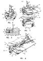
- FIGURE I is a perspective view of a first embodiment of the present invention showing first and second zipper terminals aligned just prior to engagement, the first terminal or base terminal carrying a slider adapted to fasten conventional rows of zipper teeth which are shown in phantom, the second terminal or receiving terminal being adapted to engage the slider and first terminal .in the indicated manner;
- the zipper includes interlocking elements or teeth arranged in adjacent opposing rows 12 and 14 in a conventional manner along the respective edges of flexible supporting sheets or stringers 16 and 18.
- the device 10 includes a first terminal or slider base terminal 20 and a second terminal or receiving terminal 22.
- the slider base terminal 20 is adapted to carry a slider 24, which is illustrated separately in FIGURE 3.
- the slider 24 is manually operable for fastening the zipper rows 12 and 14 by means of a handle 26 pivotally mounted atop the slider 24.
- a disc 28 is affixed to the bottom of the slider 24 as seen best in FIGURE 3.
- the purpose and function of the disc 28 will be described in detail below.
- More conventional portions of the slider 24 include top and bottom plates 30 and 32 held in spaced-apart parallel planes by a center post 34.
- the top plate 30 is provided with downwardly extending rims 36 and the bottom plate 32 is provided with upwardly extending rims 38 .
- Adjacent opposing pairs of such rims 36 and 3 8 define conventional side slots through which the stringers 16 and 18 pass as the slider 24 travels along the zipper rows 12 and 14.
- the teeth in the opposed rows 12 and 14 enter respective slider ports 40 and 42 defined between the center post 34 and the respective front edges of the rims 36 and 38.
- the individual teeth are progressively brought into interlocking engagement within the slider 24 in the conventional manner.
- the stringers 16 and 18 are ordinarily flexible, the full length of each stringer will not necessarily lie in a single plane. However, portions of the stringers 16 and 18 will lie in what will be referred to herein as the "slider working plane" as they pass through the slider 24. It will be appreciated that the slider working plane is parallel to and lies intermediate the planes defined by the top and bottom plates 30 and 32 of the slider 24.
- the terminals 20 and 22 are securely fastened to the respective zipper rows 12 and 14 by attaching the stringers 16 and 18 to respective wing plates 44 and 46 on each terminal 20 and 22
- the wings 44 and 46 lie in the same planes as their respective stringers 12, and 14 and become coplanar in the slider working plane whenever the terminals 20 and 22 are operativly engaged as seen in FIGURE 2.
- the wings 44 and 46 are sufficiently thin that they can pass through the side slots of the slider 24, which can therefore be readily moved from the position shown in FIGURE 2 to its rearmost position within the receiving terminal 22.
- the receiving terminal 22 includes a floor plate 48 lying in a plane below and parallel to the wing 46, as seen best in the view of FIGURE 1.
- a sidewall 50 extends upward from the periphery of the floor 48 to support the wing 46.
- the sidewall 50 includes a rearward portion 52 which is curved through an arc of 180 degrees so that the disc 28 can move forward out of the receiving terminal 22 as the slider 24 is pulled forward to fasten the zipper rows 12 and 14.
- the wing 46 includes a curved edge 54 which lies in the same circular arc defined by the interior surface of the curved rearward portion 52 of the sidewall 50.
- the curved edge 54 and the upper interior edge of the wall portion 52 define an aperture 56 extending through an are of about 270 degrees for receiving the disc 28 as the slider 24 is brought down into the terminal 22 from the position illustrated in FIGURE 1.
- the disc 28 includes a chamfered lower edge 58 adapted to facilitate guiding the disc 28 into the receiving aperture 56.
- the terminals 20 and 22 In order to fasten the zipper, the terminals 20 and 22 must first be brought into interlocking engagement as depicted in FIGURE 2 from a separated position as depicted in FIGURE 1. Briefly, with the slider 24 in its rearmost position on the slider base terminal 20 the assembly of the slider 24 and terminal 20 is first oriented relative to the receiving terminal 22 substantially as shown in FIGURE 1 and then brought down into the terminal 22 until a locking element 60 extending rearward from the slider base terminal 20 meets a ramp 62 formed by an upper edge of the sidewall 50.
- the assembly of the slider 24 and its base terminal 20 is then rotated relative to the receiving terminal 22 in the direction indicated by the curved arrow in FIGURE 1 until the locking element 60 moves into a notch 64 formed within the sidewall 50 at the lower rearward end of the ramp 62.
- the wings 44 and 46 will have become essentially coplanar and the bottom surface of the disc 28 will abut the top surface of the floor 48.
- the guide segments 66 and 68 will be separated transversely by a slight amount as the slider 24 begins its forward movement from its rearmost position within the terminal 22 because the center post 34 must pass between the guide segments 66 and 68.
- the degree of separation of the guide segments 66 and 68 during such initial forward movement of the slider 24 will be limited by the side rims 36 and 38 of the slider 24 engaging cooperating edges of the guide segments 66 and 68.
- the center post 34 of the slider 24 passes beyond the guide segments 66 and 68, they will be forced together within the interior passageway of the slider 24 by the side rims 36 and 38 which taper inward from front to back as will be appreciated by those skilled in the art. Any slight relative rotation of the terminals 20 and 22 during such initial forward movement of the slider 24 will not cause the locking element 60 to move entirely out of the notch 64 since the notch 64 is made long enough to compensate for such slight rotation.
- the terminals 20 and 22 will be interlocked in the position shown in FIGURE 2. Relative movement of the terminals 20 and 22 in the axial direction (i.e., the direction perpendicular to the floor 48) is prevented at the rear by the locking element 60 lodged within the notch 64 and at the front by a tongue 72 (FIGURE 1) extending transversely from the guide segment 66 into a groove 74 in the guide segment 68.
- Separation of the terminals 2o and 22 proceeds as follows.
- the slider is pulled rearward from a position such as that depicted in Figure 2 until the disc enters the terminal 22 and reaches its rearmost position therein.
- the center post 34 of the slider 24 passes between and separates the guide segments 66 and 68, which causes a slight initial rotation of the terminals 2o and 22. Since the zipper rows 12 and 14 are no longer interlocked, the terminals 2o and 22 are free to continue-their rotation relative to each other until the locking element 6o is withdrawn from. the notch 64.
- the terminals 2o and 22 can be separated by pulling axially upward on the wing 44 and axially downward on the wing 46 to return the terminals 2o and 22 to a separated position such as depicted in Figure 1. Although the terminals 2o and 22 can thus be separated, rearward movement of the slider 24 off its base terminal 2o is prevented by an end stop 78 extending upwardly from the terminal 2o to contact a rearward wall portion 8 0 of the slider 24, as seen in the sectional view of Figure 4.
- a mechanism which tends to hold the slider 24 in its rearmost position on the slider base terminal 2o to facilitate handling the slider 24 and the terminal 2o together as a unit will now be described with reference to Figure 4.
- a pointed pin 82 Housed within the thickened rearward portion of the terminal 2o is a pointed pin 82 which is biased by a spring 84 to extend the pin 82 by a predetermined amount out from the bottom of the terminal 2o .
- the pointed tip of pin 82 will lodge in an indentation 86 in the top surface of the bottom slider plate 32, thereby tending to keep the the slider 24 in the position shown.
- the handle 26 can be urged forward without great effort to cause the pin 82 to lift up as the indentation 86 moves forward beyond the pin 82.
- the pin 82 will snap back into its fully extended position when the rearward edge of the bottom slider plate 32 passes beyond the pin 82. It will be appreciated that the foregoing sequence of events occurs in reverse order when the slider 24 is returned to its rearmost position.
- the device 10 enables the connection of the ends of a seperable zipper with relative ease when compared to prior-art devices employing the conventional pin-and-socket terminals.
- the principle advantage of the present invention over such prior-art devices is the relatively large size of the disc 28 and its cooperating receiving aperture 56 which permit the terminals 20 and 22 to be brought together conveniently in the direction perpendicular to the slider working. plane and then interlocked by a slight rotational movement. It has been found that such an arrangement requires less dexterity to operate than the conventional pin-and-socket terminal arrangement.
- the device 10 can readily be adapted to permit its engagement and the fastening of the zipper rows 12 and 14 with one hand by the wearer. This is accomplished by securing gripper strips (not shown), such as the material sold under the trademark Velcro, to the back outer surface (not visible in the illustrated views) of the floor plate 48 and on a front surface of a belt buckle (not shown) or the like of the wearer. The wearer will then be able to secure the receiving terminal 22 to the belt buckle. Next, the slider disc 28 can be inserted into the aperture 56 and slider 24 and terminal 20 rotated to interlock the element 60 in the notch 64. Finally, the wearer can pull the slider 24 forward using the handle 26 to fasten the zipper rows 12 and 14. It will be appreciated that each of the foregoing steps can be performed using only one hand.
- a zipper terminal device of my invention is designated generally by reference numeral 110 in FIGURES 7-11.
- the device 110 is designed to facilitate connecting the ends of the type of separable zipper sometimes referred to in the art as a two-way slide fastener which employs a first slider for fastening the zipper rows and a second slider for at least partially unfastening the zipper rows to permit the zipper to be open at both ends and fastened in the middle.
- the device 110 includes a slider base terminal 120, which is separately illustrated in FIGURE 6, and a receiving terminal 122, which is separately illustrated in FIGURE 5.
- the terminals 120 and 122 are securely fastened at the rearmost ends of zipper rows 112 and 114 which are schematically depicted in phantom along with their supporting stringers 116 and 118 in FIGURES 5 and 6.
- the zipper rows 112 and 114 and stringers 116 and 118 are not shown in FIGURES 7-9 for ease and clarity of illustration.
- the slider base terminal 120 is adapted to carry two back-to-back sliders consisting of a leading slider 124a and a trailing slider 124b.
- the sliders 124a and 124b are manually operable by means of pivotally mounted handles 126a and 126b, respectively.
- a disc 128 is disposed in overlapping relationship on the bottom surfaces of the sliders 124a and 124b.
- the disc 128 comprises a first semicircular portion 128a affixed to the bottom of the leading slider 124a and a second semicircular portion 128b affixed to the bottom of the trailing slider 124b.
- the sliders 124a and 124b include top and bottom plates with adjoining side rims, the plates being interconnected by respective center posts 134a and 134b, all of which are essentially conventional in construction like their corresponding parts in the single-slider embodiment 10 previously described with reference to FIGURES 1-4.
- the leading slider 124a has right and left slider ports 140a and 142a on opposite sides of the center post 134a, as seen best in FIGURE 8.
- the trailing slider 124b has right and left slider ports 140b and 142b on opposite sides of the center post 134b, as seen best in FIGURE 7.
- the terminals 120 and 122 are securely fastened to their respective zipper rows 112 and 114 by attaching the stringers 116 and 118 to respective wing plates 144 and 146 in a suitable manner.
- the wings 144 and 146 lie in the same planes as their respective stringers 112 and 114 and become coplanar in the slider working plane whenever the terminals 120 and 122 are operatively engaged, such as in FIGURE 9.
- the receiving terminal 122 includes a floor 148 lying in a plane below and parallel to the wing 146, the floor 148 and wing 146 being interconnected by one side of a generally U-shaped sidewall 150.
- the sidewall 150 includes a semicircular rearward portion 152 adapted to receive the disc 128 during initial engagement of the terminals 120 and 122.
- the forward portions of the sidewalls 150 are provided with shelves 153a and 153b which extend transversely inward.
- the shelves 153a and 153b terminate rearwardly in curved edges 154a and 154b, respectively, and together with the curved wall portion 152 provide an arced receiving aperture 156 subtending an angle somewhat in excess of 180 degrees.
- the disc 128 includes a chamfered lower edge 158 (FIGURE 7) adapted to facilitate guiding the disc 128 into the receiving aperture 156 as the assembly of the sliders 124a and 124b and their base terminal 120 are brought down into engagement with the terminal 122 from the position shown in FIGURE 8.
- the disc half 128b on the trailing slider 124b includes a locking element 160 in the form of a flat tongue-like flange protruding transversely from the top left surface of the disc half 128b , as shown in FIGURE 8 and seen in dotted outline in FIGURE 11. When the terminals are initially engaged, the locking element 160 comes to rest on a shoulder 162, which is visible in FIGURE 8.
- the shoulder 162 extends rearward into a notch 164 formed within the sidewall 150 under an overhanging shelf 165.
- the locking element 160 is adapted to lodge within the notch 164 to assist in interlocking the terminals 120 and 122, as will be described more fully below.
- the slider base terminal 120 is provided with an elongated guide segment 166 which curves slightly to the right away from the rearward projection of the zipper row 112.
- the elongated guide segment 166 extends through the right side of each slider as seen best in FIGURE 7.
- the receiving terminal 122 includes a guide segement 168 cantilevered inward from the forward portion of the wing plate 146.
- the guide segment 168 is adapted to guide the center post 134a into operative proximity with the rearmost end of the zipper row 114 as will be appreciated from the view of FIGURE 9.
- the guide segment 166 includes a tongue 172 adapted to mate with a groove 174 in the guide segment 168.
- the terminal 122 is provided with an end stop 178, as shown in FIGURE 6.
- the end stop 178 extends above the adjacent top surface of the guide segment 166 so that the end stop 178 will lodge within a recessed surface 180 under the top plate of the slider 124b as seen in FIGURE 7, thereby preventing rearward movement of the slider 124b from the position shown in FIGURE 7.
- the slider base terminal 120 is provided with a circular plate 190 which is carried below the wing 144 by means of a downwardly extending rod 192.
- the plate 190 is adapted to lodge partially within a notch 194 in an upper surface portion of the disc half 128b when the slider 124b is in its rearmost p ostion on the terminal 120 as seen in FIGURE 7.
- the plate 190 extends outward from the disc half 128b so that it will come to rest on a recessed surface 196 in the curved rearward portion 152 of the sidewall 150 as depicted in FIGURE 8.
- the terminal 122 is provided with a slot 198 and an outlet 200 adapted to permit the rod 192 and plate 190 to pass laterally out the sidewall 150 in order to separate the terminals 120 and 122 as will be described more fully below with reference to FIGURE 11.
- the terminals 120 and 122 are operatively engaged by bringing them together in the axial direction (i.e., the direction perpendicular to the floor 148) so that the disc 128 nests down within the receiving aperture 156.
- the slider base terminal 120 is then rotated relative to the receiving terminal 122 in the direction indicated by the arrow in FIGURE 8 in order to bring the guide segment 168 into alignment in front of the left slider port 142a as depicted in FIGURE 9.
- the locking element 160 moves into the notch 164, which is visible in FIGURE 8, in order to prevent axial movement of the terminals 120 and 122 relative to each other.
- the outer edge of the circular plate 190 will have moved from its initial resting position on the recessed surface 196 under the rearward portions of the shelf 153b stradled by the slot 198.
- the leading slider 124a can be pulled up the zipper rows 112 and 114 to progressively fasten the teeth as depicted in FIGURE 10.
- the trailing slider 124b is left in its rearmost position, the terminals 120 and 122 will remain interlocked against separation. Relative movement in the axial direction is prevented at the rear by the floor 148 abutting the bottom of the disc half 128b, the locking element 160 lodged under the shelf 165, and the circular plate 190 lodged under the rearward portions of the shelf 153b.
- Relative movement of the terminals 120 and 122 in the axial direction is prevented at the front by the interlocked tongue 172 and groove 174, which are seen separated in FIGURE 9. Relative movement of the terminals 120 and 122 in the transverse directions is prevented by the disc half 128b nested rearwardly within the sidewall 150, the interlocking effect of the rearmost zipper teeth 112a and 114a, and the side rims of the slider 124b grasping the adjacent edges of the elongated guide segment 166.
- the shelves 153a and 153b and the adjacent portions of the wall 150 and floor 148 below the shelves 153a and 153b serve as guide chutes for the edges of the disc halves 128a and 128b which extend beyond the sides of their respective sliders 124a and 124b, thereby keeping the sliders 124a and 124b in proper alignment for engaging the rearmost ends of the zipper rows 112 and 114.
- the rearward ends of the zipper rows ll2 and 114 can be separated by pulling the trailing slider 124b forward as far as desired up to the point where it once again abuts the leading slider 124a.
- the sliders 124a and 124b are shown relatively close to the terminals 120 and 122 for ease of illustration, it will be appreciated that the leading slider 124a can be pulled any desired distance up the zipper rows 112 and 114 up to the opposite end (not shown) and that the trailing slider 124b can be positioned at any point between its rearmost position as seen in FIGURE 10 and the leading slider 124a.
- the separation of the terminals 120 and 122 is achieved as follows.
- the center post 134b (visible more clearly in FIGURE 7) progressively forces the elongated guide segment 166 to the right by bearing against a curved inner face 202 extending along the length of the guide segment 166.
- the initial forward movement of the slider 124b forces the rod 192 out through the slot 198 since the rod 192 is carried on the terminal 120 in fixed relationship to the guide segment 166.
- the tongue 172 at the forward end of the guide segment 166 pulls free from its mating groove 174 in the guide segment 168.
- the center post 134b begins to progressively disengage the individual zipper teeth in the rows 112 and 114.
- the slider 124b is shown after having just passed beyond the rearmost zipper teeth 112a and 114a.
- the terminals 120 and 122 can be brought back into interlocking relationship to close the rearward ends of the zipper rows 112 and 114 by merely pulling the trailing slider 124b back into its rearmost position within the receiving terminal 122.
- the fastening action of the slider 124b working on the zipper rows 112 and 114 pulls the guide segments 166 and 168 into proper position for passing into the respective slider ports 140b and 142b (visible in FIGURE 7).
- the guide segments 166 and 168 begin to move through the slider 124b, thereby causing the base terminal 120 to begin to swing toward the receiving terminal 122.
- the disc half 128b will have moved between the forward ends of the U-shaped sidewall 150 and under the shelves 153a and 153b, thus assuring that the slider 124b will be guided properly back into its rearmost position in terminal 122.
- the rod 192 is pulled back through the slot 198 and finally comes to rest in the notch 194 in the disc half 128b, as previously described with reference to FIGURE 7.
- leading slider 124a can then be moved rearward to unfasten the zipper rows 112 and 114 and then be pulled into abutting relationship with the trailing slider 124b to return to the position shown in FIGURE 9.
- Disconnecting the terminals 120 and 122 is then easily achieved by merely rotating the terminals in the direction opposite from the arrow shown in FIGURE 8 until the locking element 160 is withdrawn from the notch 164, whereupon pulling upward on the wing 144 and downward on the wing 146 will achieve separation.
- the device 110 enables the connection of the ends of the a two-way slide fastener with relative ease when compared to prior-art devices employing the conventional pin-and-socket terminals.
- the terminals 120 and 122 are thus engaged and interlocked, they cannot be separated by the mere forward movement of the leading slider 124a, which occurrence has been a problem with conventional pin-and-socket terminal devices.
- the disc 128 is an integral piece secured entirely to the bottom of either slider 124a or 124b and the other slider is essentially conventional in construction.
Landscapes
- Bag Frames (AREA)
Abstract
An improved device for fastening a separable zipper includes specially adapted terminals (20,22) at the respective ends of opposed rows of zipper teeth (12,14) and a specially adapted slider (24) supported by one of the terminals. The slider is provided with a disc (28) which can be inserted in a cooperating aperture of the other terminal by movement in a direction substantially perpendicular to the zipper rows. A second embodiment of the invention includes specially adapted terminals and two sliders (124a, 124b), the sliders being disposed in back-to-back relationship and supported on one (120) of the terminals, the sliders including a disc separable into semicircular halves (128a, 128b) for guiding the sliders into nesting engagement with the other terminal (122) by movement in the direction substantially perpendicular to the zipper rows.
Description
- The present invention pertains generally to slide fasteners and more particularly to the type of slide fastener commonly known as a zipper which has opposed strings or rows of interlocking elements or zipper teeth which are brought into interlocking engagement by the movement of a slider in one direction along the rows and disengaged or unfastened by movement of the slider in the opposite direction.
- The present invention addresses the problem of reducing the difficulty involved with the initial engagement of the ends of a separable zipper on a jacket or similar garment. It will be appreciated, however, that the solution provided by the present invention has useful application to the entire field of slide fasteners. The present invention permits the ends of a separable zipper to be interconnected and the zipper to be fastened with a minimum of care and dexterity.
- In accordance with a first " aspect of the invention, a device for connecting the ends of a separable zipper includes a slider having first and second ports separated by a center post at the front of the slider, the ports being adapted to receive first and second opposed rows of zipper teeth and guide the zipper teeth into a common passageway rearward from the center post within which the teeth in the opposed rows are progressively forced into interlocking engagement as the slider is pulled forward, a base terminal disposed at the rearward end of the first row of teeth and a receiving terminal disposed at the rearward end of the second row of teeth, the base terminal being adapted to carry the slider when the rows are fully disengaged and the terminals are seperated and there being on the bottom of the slider means for guiding the slider, when in its rearmost position on the base terminal, into a cooperating aperture in the receiving terminal by movement in a direction generally perpendicular to the plane through which the zipper rows move when passing through the slider.
- In accordance with a second aspect of the invention, a device for connecting the ends of a separable zipper having first and second opposed rows of zipper teeth includes a leading slider and a trailing slider adapted to progressively engage the zipper rows by the forward movement of the leading slider and progressively disengage the zipper rows by the forward movement of the trailing slider following in the path of the leading slider, a base terminal disposed at the rearward end of the first row of teeth and a receiving terminal disposed at the rearward end of the second row of teeth, the base terminal being adapted to carry the sliders when the rows of teeth are fully disengaged and the terminals are separated and there being on the bottom of at least one of the sliders a disc for guiding the sliders, when in their rearmost position on the base terminal, into a cooperating aperture in the receiving terminal by movement in a direction generally perpendicular to the plane through which the zipper rows move when passing through the sliders.
- Two examples of devices in accordance with the invention will now be described with reference to the accompanying drawings wherein:
- FIGURE I is a perspective view of a first embodiment of the present invention showing first and second zipper terminals aligned just prior to engagement, the first terminal or base terminal carrying a slider adapted to fasten conventional rows of zipper teeth which are shown in phantom, the second terminal or receiving terminal being adapted to engage the slider and first terminal .in the indicated manner;
- FIGURE 2 is a perspective view showing the terminals interlocked in operative engagement and the slider moved slightly forward up the rows of zipper teeth;
- FIGURE 3 is a perspective view of the specially adapted slider shown separately;
- FIGURE 4 is a vertial cross-section of the slider and a rearward portion of the base terminal taken along the line 4-4 of FIGURE 1 in the direction indicated;
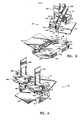
- FIGURE 5 is a top plan view of a receiving terminal in accordance with a second embodiment of the invention;
- FIGURE 6 is a top plan view of a base terminal in accordance with the second embodiment;
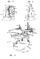
- FIGURE 7 is a perspective view from below and slighty rearward of the terminals of FIGURES 5 and 6, including first and second back-to-back sliders in their rearmost position on the base terminal, the sliders and terminals being aligned just prior to being brought into operative engagement in the indicated manner;
- FIGURE 8 is a perspective view of the sliders and terminals oriented in the same relative position as in FIGURE 7 but looking from an overhead forward point of view from which the right sides of the sliders are visible;
- FIGURE 9 is a perspective view of the sliders and terminals interlocked in operative engagement looking from an overhead forward point of view from which the left sides of the sliders are visible;
- FIGURE 10 is a perspective view from essentially the same point of view as FIGURE 9 but with the first slider pulled forward to fasten the rearmost ends of the zipper rows; and
- FIGURE 11 is a perspective view from a slightly higher elevation than FIGURE 10 but with the second slider pulled forward to disengage the terminals and the rearmost zipper teeth.
- Referring to FIGURES 1-4, a device for connecting the ends of a separable zipper is illustrated and designated generally by
reference 10. With particular reference to FIGURE 2, the zipper includes interlocking elements or teeth arranged in adjacentopposing rows stringers device 10 includes a first terminal orslider base terminal 20 and a second terminal or receivingterminal 22. As see in FIGURE 1, theslider base terminal 20 is adapted to carry aslider 24, which is illustrated separately in FIGURE 3. Theslider 24 is manually operable for fastening thezipper rows handle 26 pivotally mounted atop theslider 24. Pulling theslider 24 forward as indicated by the arrow 27 in FIGURE 2 engages thezipper rows slider 24 in the opposite or rearward direction. In as much as thezipper rows stringers - In accordance with a unique feature of the present invention, a
disc 28 is affixed to the bottom of theslider 24 as seen best in FIGURE 3. The purpose and function of thedisc 28 will be described in detail below. More conventional portions of theslider 24 include top andbottom plates center post 34. Thetop plate 30 is provided with downwardly extendingrims 36 and thebottom plate 32 is provided with upwardly extending rims 38. Adjacent opposing pairs ofsuch rims stringers slider 24 travels along thezipper rows slider 24 moves forward, the teeth in theopposed rows respective slider ports center post 34 and the respective front edges of therims zipper rows slider 24, the individual teeth are progressively brought into interlocking engagement within theslider 24 in the conventional manner. Since thestringers stringers slider 24. It will be appreciated that the slider working plane is parallel to and lies intermediate the planes defined by the top andbottom plates slider 24. - The
terminals respective zipper rows stringers respective wing plates terminal - The
wings respective stringers terminals wings slider 24, which can therefore be readily moved from the position shown in FIGURE 2 to its rearmost position within thereceiving terminal 22. - The
receiving terminal 22 includes a floor plate 48 lying in a plane below and parallel to thewing 46, as seen best in the view of FIGURE 1. Asidewall 50 extends upward from the periphery of the floor 48 to support thewing 46. Thesidewall 50 includes arearward portion 52 which is curved through an arc of 180 degrees so that thedisc 28 can move forward out of thereceiving terminal 22 as theslider 24 is pulled forward to fasten thezipper rows wing 46 includes a curved edge 54 which lies in the same circular arc defined by the interior surface of the curvedrearward portion 52 of thesidewall 50. The curved edge 54 and the upper interior edge of thewall portion 52 define an aperture 56 extending through an are of about 270 degrees for receiving thedisc 28 as theslider 24 is brought down into theterminal 22 from the position illustrated in FIGURE 1. Thedisc 28 includes a chamferedlower edge 58 adapted to facilitate guiding thedisc 28 into the receiving aperture 56. - In order to fasten the zipper, the
terminals slider 24 in its rearmost position on theslider base terminal 20 the assembly of theslider 24 andterminal 20 is first oriented relative to thereceiving terminal 22 substantially as shown in FIGURE 1 and then brought down into theterminal 22 until alocking element 60 extending rearward from theslider base terminal 20 meets aramp 62 formed by an upper edge of thesidewall 50. While forcing theterminals slider 24 and itsbase terminal 20 is then rotated relative to thereceiving terminal 22 in the direction indicated by the curved arrow in FIGURE 1 until thelocking element 60 moves into anotch 64 formed within thesidewall 50 at the lower rearward end of theramp 62. At this stage, thewings disc 28 will abut the top surface of the floor 48. Once theterminals slider 24 can be pulled forward up thezipper rows Guide segments wings slider 24 in the proper direction - Pulling the
slider 24 forward from its rearmost position to fasten thezipper rows slider base terminal 20 to move forward relative to the receiving teiminal 22 since thelocking element 60 is provided withflanged portions 70 which abut the outer vertical surface of thesidewall 50 as depicted in FIGURE 2. - It will be appreciated that the
guide segments slider 24 begins its forward movement from its rearmost position within theterminal 22 because thecenter post 34 must pass between theguide segments guide segments slider 24 will be limited by theside rims slider 24 engaging cooperating edges of theguide segments center post 34 of theslider 24 passes beyond theguide segments slider 24 by theside rims terminals slider 24 will not cause thelocking element 60 to move entirely out of thenotch 64 since thenotch 64 is made long enough to compensate for such slight rotation. - Once the
slider 24 has been pulled forward to at least partially fasten thezipper rows terminals terminals locking element 60 lodged within thenotch 64 and at the front by a tongue 72 (FIGURE 1) extending transversely from theguide segment 66 into agroove 74 in theguide segment 68. Pulling apart theterminals arrows 75 in FIGURE 2, is prevented at the rear once again by thelocking element 60 nested within thenotch 64 at the front by the interlocking effect of at least the rearmost teeth 12a and 14a of thezipper rows terminals locking element 60 from thenotch 64 is prevented by a downwardly extending post 76 (shown in dotted outline) which is secured to the underside of thewing 44 and abuts the outer edge of the sidewall 5o when theterminals 2o and 22 are interlocked as shown in Figure 2. - Separation of the
terminals 2o and 22 proceeds as follows. The slider is pulled rearward from a position such as that depicted in Figure 2 until the disc enters theterminal 22 and reaches its rearmost position therein. During this process, thecenter post 34 of theslider 24 passes between and separates theguide segments terminals 2o and 22. Since thezipper rows terminals 2o and 22 are free to continue-their rotation relative to each other until the locking element 6o is withdrawn from. thenotch 64. During such rotation, the post 76'slides rearward along the outer surface of the of the sidewall 5o. Once the locking element 6o has been withdrawn from thenotch 64, theterminals 2o and 22 can be separated by pulling axially upward on thewing 44 and axially downward on thewing 46 to return theterminals 2o and 22 to a separated position such as depicted in Figure 1. Although theterminals 2o and 22 can thus be separated, rearward movement of theslider 24 off its base terminal 2o is prevented by anend stop 78 extending upwardly from the terminal 2o to contact a rearward wall portion 80 of theslider 24, as seen in the sectional view of Figure 4. - As an optional desirable feature of the inventive device 10, a mechanism which tends to hold the
slider 24 in its rearmost position on the slider base terminal 2o to facilitate handling theslider 24 and the terminal 2o together as a unit will now be described with reference to Figure 4. Housed within the thickened rearward portion of the terminal 2o is a pointed pin 82 which is biased by aspring 84 to extend the pin 82 by a predetermined amount out from the bottom of the terminal 2o . When theslider 24 is in its rearmost position on the terminal 2o as depicted in Figure 4, the pointed tip of pin 82 will lodge in anindentation 86 in the top surface of thebottom slider plate 32, thereby tending to keep the theslider 24 in the position shown. However, when it is desired to move theslider 24 forward, thehandle 26 can be urged forward without great effort to cause the pin 82 to lift up as theindentation 86 moves forward beyond the pin 82. The pin 82 will snap back into its fully extended position when the rearward edge of thebottom slider plate 32 passes beyond the pin 82. It will be appreciated that the foregoing sequence of events occurs in reverse order when theslider 24 is returned to its rearmost position. - . It will be appreciated from the foregoing description that the
device 10 enables the connection of the ends of a seperable zipper with relative ease when compared to prior-art devices employing the conventional pin-and-socket terminals. The principle advantage of the present invention over such prior-art devices is the relatively large size of thedisc 28 and its cooperating receiving aperture 56 which permit theterminals - Another advantage which is inherent in the design of the
device 10 when employed with the zipper on a jacket or similar item of apparel is that thedevice 10 can readily be adapted to permit its engagement and the fastening of thezipper rows terminal 22 to the belt buckle. Next, theslider disc 28 can be inserted into the aperture 56 andslider 24 and terminal 20 rotated to interlock theelement 60 in thenotch 64. Finally, the wearer can pull theslider 24 forward using thehandle 26 to fasten thezipper rows - Another embodiment of my invention will now be described with reference to FIGURES 5-11. A zipper terminal device of my invention is designated generally by
reference numeral 110 in FIGURES 7-11. Thedevice 110 is designed to facilitate connecting the ends of the type of separable zipper sometimes referred to in the art as a two-way slide fastener which employs a first slider for fastening the zipper rows and a second slider for at least partially unfastening the zipper rows to permit the zipper to be open at both ends and fastened in the middle. - The
device 110 includes aslider base terminal 120, which is separately illustrated in FIGURE 6, and a receivingterminal 122, which is separately illustrated in FIGURE 5. Theterminals zipper rows stringers zipper rows stringers - As seen best in FIGURE 8, the
slider base terminal 120 is adapted to carry two back-to-back sliders consisting of a leading slider 124a and a trailingslider 124b. Thesliders 124a and 124b are manually operable by means of pivotally mountedhandles 126a and 126b, respectively. As seen in FIGURE 7, adisc 128 is disposed in overlapping relationship on the bottom surfaces of thesliders 124a and 124b. Thedisc 128 comprises a first semicircular portion 128a affixed to the bottom of the leading slider 124a and a secondsemicircular portion 128b affixed to the bottom of the trailingslider 124b. When thesliders 124a and 124b are in their rearmost abutting positions on thebase terminal 120 as seen in FIGURE 7, thedisc halves 128a and 128b are kept in longitudinal alignment by a tongue-and-groove arrangement seen in dotted outline and designated by reference numeral 129. - Referring to FIGURES 8 and 9, the
sliders 124a and 124b include top and bottom plates with adjoining side rims, the plates being interconnected byrespective center posts 134a and 134b, all of which are essentially conventional in construction like their corresponding parts in the single-slider embodiment 10 previously described with reference to FIGURES 1-4. The leading slider 124a has right and left slider ports 140a and 142a on opposite sides of the center post 134a, as seen best in FIGURE 8. Likewise, the trailingslider 124b has right and leftslider ports center post 134b, as seen best in FIGURE 7. - With reference again to FIGURES 5 and 6, the
terminals respective zipper rows stringers respective wing plates wings respective stringers terminals - Referring again to FIGURE 8, the receiving
terminal 122 includes afloor 148 lying in a plane below and parallel to thewing 146, thefloor 148 andwing 146 being interconnected by one side of a generallyU-shaped sidewall 150. Thesidewall 150 includes a semicircularrearward portion 152 adapted to receive thedisc 128 during initial engagement of theterminals sidewalls 150 are provided withshelves 153a and 153b which extend transversely inward. Theshelves 153a and 153b terminate rearwardly incurved edges 154a and 154b, respectively, and together with thecurved wall portion 152 provide an arced receivingaperture 156 subtending an angle somewhat in excess of 180 degrees. Thedisc 128 includes a chamfered lower edge 158 (FIGURE 7) adapted to facilitate guiding thedisc 128 into the receivingaperture 156 as the assembly of thesliders 124a and 124b and theirbase terminal 120 are brought down into engagement with the terminal 122 from the position shown in FIGURE 8. Thedisc half 128b on the trailingslider 124b includes alocking element 160 in the form of a flat tongue-like flange protruding transversely from the top left surface of the disc half 128b, as shown in FIGURE 8 and seen in dotted outline in FIGURE 11. When the terminals are initially engaged, the lockingelement 160 comes to rest on ashoulder 162, which is visible in FIGURE 8. Theshoulder 162 extends rearward into anotch 164 formed within thesidewall 150 under an overhangingshelf 165. The lockingelement 160 is adapted to lodge within thenotch 164 to assist in interlocking theterminals - Referring briefly again to FIGURE 6, the
slider base terminal 120 is provided with anelongated guide segment 166 which curves slightly to the right away from the rearward projection of thezipper row 112. When thesliders 124a and 124b are in their rearmost position on thebase terminal 120, theelongated guide segment 166 extends through the right side of each slider as seen best in FIGURE 7. - Referring briefly again to FIGURE 5, the receiving
terminal 122 includes aguide segement 168 cantilevered inward from the forward portion of thewing plate 146. Theguide segment 168 is adapted to guide the center post 134a into operative proximity with the rearmost end of thezipper row 114 as will be appreciated from the view of FIGURE 9. As seen in FIGURES 8 and 9, theguide segment 166 includes atongue 172 adapted to mate with agroove 174 in theguide segment 168. - In order to keep the
sliders 124a and 124b on theslider base terminal 120 when theterminals end stop 178, as shown in FIGURE 6. Theend stop 178 extends above the adjacent top surface of theguide segment 166 so that theend stop 178 will lodge within a recessedsurface 180 under the top plate of theslider 124b as seen in FIGURE 7, thereby preventing rearward movement of theslider 124b from the position shown in FIGURE 7. - Referring again to FIGURES 7 and 8, the
slider base terminal 120 is provided with acircular plate 190 which is carried below thewing 144 by means of a downwardly extendingrod 192. Theplate 190 is adapted to lodge partially within anotch 194 in an upper surface portion of thedisc half 128b when theslider 124b is in its rearmost postion on the terminal 120 as seen in FIGURE 7. Theplate 190 extends outward from thedisc half 128b so that it will come to rest on a recessedsurface 196 in the curvedrearward portion 152 of thesidewall 150 as depicted in FIGURE 8. The terminal 122 is provided with aslot 198 and anoutlet 200 adapted to permit therod 192 andplate 190 to pass laterally out thesidewall 150 in order to separate theterminals - The operation of the
device 110 will now be described. With thesliders 124a and 124b in their rearmost positions on theslider base terminal 120 and the terminal 120 oriented at a slight angle relative to the receivingterminal 122 as shown in FIGURES 7 and 8, theterminals disc 128 nests down within the receivingaperture 156. Theslider base terminal 120 is then rotated relative to the receivingterminal 122 in the direction indicated by the arrow in FIGURE 8 in order to bring theguide segment 168 into alignment in front of the left slider port 142a as depicted in FIGURE 9. Once rotated into the position seen in FIGURE 9, the lockingelement 160 moves into thenotch 164, which is visible in FIGURE 8, in order to prevent axial movement of theterminals terminals circular plate 190 will have moved from its initial resting position on the recessedsurface 196 under the rearward portions of theshelf 153b stradled by theslot 198. - Once the
terminals zipper rows slider 124b is left in its rearmost position, theterminals floor 148 abutting the bottom of thedisc half 128b, the lockingelement 160 lodged under theshelf 165, and the circular plate 190 lodged under the rearward portions of theshelf 153b. Relative movement of theterminals tongue 172 andgroove 174, which are seen separated in FIGURE 9. Relative movement of theterminals disc half 128b nested rearwardly within thesidewall 150, the interlocking effect of the rearmost zipper teeth 112a and 114a, and the side rims of theslider 124b grasping the adjacent edges of theelongated guide segment 166. During the forward movement of thesliders 124a and 124b, theshelves 153a and 153b and the adjacent portions of thewall 150 andfloor 148 below theshelves 153a and 153b serve as guide chutes for the edges of thedisc halves 128a and 128b which extend beyond the sides of theirrespective sliders 124a and 124b, thereby keeping thesliders 124a and 124b in proper alignment for engaging the rearmost ends of thezipper rows - Referring to FIGURE 11, it will be appreciated that the rearward ends of the zipper rows ll2 and 114 can be separated by pulling the trailing
slider 124b forward as far as desired up to the point where it once again abuts the leading slider 124a. Although thesliders 124a and 124b are shown relatively close to theterminals zipper rows slider 124b can be positioned at any point between its rearmost position as seen in FIGURE 10 and the leading slider 124a. - With reference to FIGURES 10 and 11, the separation of the
terminals slider 124b is pulled forward from its rearmost position as seen in FIGURE 10, thecenter post 134b (visible more clearly in FIGURE 7) progressively forces theelongated guide segment 166 to the right by bearing against a curvedinner face 202 extending along the length of theguide segment 166. The initial forward movement of theslider 124b forces therod 192 out through theslot 198 since therod 192 is carried on the terminal 120 in fixed relationship to theguide segment 166. As theslider 124b continues its forward movement, thetongue 172 at the forward end of theguide segment 166 pulls free from itsmating groove 174 in theguide segment 168. As theslider 124b exits fromterminal 122, thecenter post 134b begins to progressively disengage the individual zipper teeth in therows slider 124b is shown after having just passed beyond the rearmost zipper teeth 112a and 114a. - It will be appreciated from FIGURE 11 that the
terminals zipper rows slider 124b back into its rearmost position within the receivingterminal 122. In particular, as thecenter post 134b of theslider 124b nears theguide segments slider 124b working on thezipper rows guide segments respective slider ports slider 124b is pulled partially into the receivingterminal 122, theguide segments slider 124b, thereby causing thebase terminal 120 to begin to swing toward the receivingterminal 122. By the time theguide segment 168 passes out the forward end of theslider 124b, thedisc half 128b will have moved between the forward ends of theU-shaped sidewall 150 and under theshelves 153a and 153b, thus assuring that theslider 124b will be guided properly back into its rearmost position interminal 122. As theslider 124b approaches its rearmost position, therod 192 is pulled back through theslot 198 and finally comes to rest in thenotch 194 in thedisc half 128b, as previously described with reference to FIGURE 7. It will of course be appreciated that the leading slider 124a can then be moved rearward to unfasten thezipper rows slider 124b to return to the position shown in FIGURE 9. Disconnecting theterminals locking element 160 is withdrawn from thenotch 164, whereupon pulling upward on thewing 144 and downward on thewing 146 will achieve separation. - Those skilled in the art will appreciate from the foregoing description that the
device 110 enables the connection of the ends of the a two-way slide fastener with relative ease when compared to prior-art devices employing the conventional pin-and-socket terminals. One merely brings thedisc 128 down into the receivingaperture 156 and rotates theterminals terminals terminals - In a modification of the device 11o, the
disc 128 is an integral piece secured entirely to the bottom of eitherslider 124a or 124b and the other slider is essentially conventional in construction.
Claims (10)
1. A device for connecting the ends of a separable zipper of the type having first and second rows (12,14) of teeth disposed along the opposed edges of supporting stringers (16,18), the .device comprising:
a slider (24) having top and bottom plates (3o,32) held in spaced-apart parallel planes by a center post (34), the plates having facing side rims (36,38) defining first and second side slots through which the stringers pass, the front edges of the side rims defining first and second ports (4o,42) on opposite sides of the center post, the ports leading to a common passageway within the slider where the teeth are progressively engaged or disengaged depending on the direction of slider movement;
a base terminal (2o) disposed at the rearward end of the first row of teeth and adapted to carry the slider when the rows are fully disengaged; and
a receiving terminal (22) disposed at the rearward end of the second row of teeth, the device being characterized in that the receiving terminal includes wall portions (50,54) defining an apetture; and in that there is on the bottom of the slider first means (28) insertable into the aperture in the direction generally perpendicular to said parallel planes to permit the ports of the slider to be aligned for receiving the rearmost ends of the rows of teeth upon forward movement of the slider.
2. The device of claim 1 further comprising:
second means (60,64, 72,72) for interlocking the terminals (2o,22) against separation when the slider is pulled forward to engage the rows of teeth.
3. The device of claim 1 or claim 2 wherein said first means (28) comprises a disc of a first diameter, and the aperture of the receiving terminal (22) defines an arc in excess of 18o degress with a diameter slightly larger than.said first diameter.
4. The device of claim 2 wherein said second means includes a locking element (60) disposed on the base terminal (2o) and adapted to lodge in a..notch (64) in the receiving terminal (22) upon rotating the terminals to bring the rearmost ends of the zipper rows into operative proximity in front of their respective slider ports.
5. The device of claim 4 further comprising a sloped ramp (62) formed on the upper edge of a curved rearward wall (5o) of the receiving terminal, and wherein the looking element (60) extends from a rearward portion of the base terminal and is adapted to be guided by the ramp into the notch by a slight relative rotation of the terminals.
6. The device of any preceding claim comprising means (82) for locating the slider (24) in its rearmost position on the base terminal (20): when the terminals are separated.
7. The device of claim 1 further comprising:
a second slider (124b) similar to the first-mentioned slider (124a) and disposed rearward from the first-mentioned slider, the second slider being oriented to progressively disengage the zipper rows upon forward movement after the zipper tows have at least been partially engaged by the forward movement of the first-menioned slider.
8. The device of claim 7 wherein said first means includes first and second semicircular portions (128a, 128b) of a disc on the bottoms of the respective first and second sliders and disposed to form a single disc when the sliders are located in their rearmost positions on the base terminal (120), the disc being insertable in the aperture of the receiving terminal (122) to bring the terminals into operative engagement.
9. The device of claim 7 or the device of claim 8 further comprising third means (160, 164, 172, 174) for interlocking the terminals against separation when the terminals are rotationally positioned so that the rearmost ends of the zipper are aligned in front of the respective ports of the first-mentioned slider.
10. The device of claim 9 wherein the third means remains operative to interlock the terminals against separation whenever the second slider (124b) is nested in the receiving terminal (122) independent of the position of the first slider (124a).
Priority Applications (1)
| Application Number | Priority Date | Filing Date | Title |
|---|---|---|---|
| EP82102940A EP0090873A1 (en) | 1982-04-06 | 1982-04-06 | Slide fastener |
Applications Claiming Priority (1)
| Application Number | Priority Date | Filing Date | Title |
|---|---|---|---|
| EP82102940A EP0090873A1 (en) | 1982-04-06 | 1982-04-06 | Slide fastener |
Publications (1)
| Publication Number | Publication Date |
|---|---|
| EP0090873A1 true EP0090873A1 (en) | 1983-10-12 |
Family
ID=8188974
Family Applications (1)
| Application Number | Title | Priority Date | Filing Date |
|---|---|---|---|
| EP82102940A Withdrawn EP0090873A1 (en) | 1982-04-06 | 1982-04-06 | Slide fastener |
Country Status (1)
| Country | Link |
|---|---|
| EP (1) | EP0090873A1 (en) |
Cited By (3)
| Publication number | Priority date | Publication date | Assignee | Title |
|---|---|---|---|---|
| WO1996004813A1 (en) * | 1994-08-13 | 1996-02-22 | J. & P. Coats, Limited | Slide fasteners |
| EP0917837A2 (en) * | 1997-11-20 | 1999-05-26 | Ykk Corporation | Separable bottom stop assembly of slide fastener |
| EP2517595A1 (en) * | 2009-12-25 | 2012-10-31 | YKK Corporation | Reverse opening slide fastener |
Citations (3)
| Publication number | Priority date | Publication date | Assignee | Title |
|---|---|---|---|---|
| US4232430A (en) * | 1979-03-15 | 1980-11-11 | Friedberg Martin F | Device for connecting the ends of a separable zipper |
| US4232429A (en) * | 1978-09-07 | 1980-11-11 | Friedberg Martin F | Sliding fastener |
| US4326319A (en) * | 1979-03-15 | 1982-04-27 | Friedberg Martin F | Slide fastener with improved end connections |
-
1982
- 1982-04-06 EP EP82102940A patent/EP0090873A1/en not_active Withdrawn
Patent Citations (3)
| Publication number | Priority date | Publication date | Assignee | Title |
|---|---|---|---|---|
| US4232429A (en) * | 1978-09-07 | 1980-11-11 | Friedberg Martin F | Sliding fastener |
| US4232430A (en) * | 1979-03-15 | 1980-11-11 | Friedberg Martin F | Device for connecting the ends of a separable zipper |
| US4326319A (en) * | 1979-03-15 | 1982-04-27 | Friedberg Martin F | Slide fastener with improved end connections |
Cited By (6)
| Publication number | Priority date | Publication date | Assignee | Title |
|---|---|---|---|---|
| WO1996004813A1 (en) * | 1994-08-13 | 1996-02-22 | J. & P. Coats, Limited | Slide fasteners |
| EP0917837A2 (en) * | 1997-11-20 | 1999-05-26 | Ykk Corporation | Separable bottom stop assembly of slide fastener |
| EP0917837A3 (en) * | 1997-11-20 | 1999-09-01 | Ykk Corporation | Separable bottom stop assembly of slide fastener |
| US6088888A (en) * | 1997-11-20 | 2000-07-18 | Ykk Corporation | Separable bottom stop assembly of slide fastener |
| EP2517595A1 (en) * | 2009-12-25 | 2012-10-31 | YKK Corporation | Reverse opening slide fastener |
| EP2517595A4 (en) * | 2009-12-25 | 2013-11-13 | Ykk Corp | Reverse opening slide fastener |
Similar Documents
| Publication | Publication Date | Title |
|---|---|---|
| USRE31487E (en) | Slide fastener with improved end connections | |
| US4232430A (en) | Device for connecting the ends of a separable zipper | |
| US4232429A (en) | Sliding fastener | |
| EP2027789A2 (en) | Slider for concealed type slide fastener with separable bottom end stop | |
| US3872551A (en) | Slide fastener having separating end stop | |
| TWI355904B (en) | Slider for slide fastener | |
| US4326319A (en) | Slide fastener with improved end connections | |
| EP2604138B1 (en) | Slide fastener | |
| CA1288219C (en) | Automatic locking slider for slide fasteners | |
| US7533451B2 (en) | Slide fastener | |
| US8813318B2 (en) | Slide fastener | |
| US4942648A (en) | Separable type water-resistant slide fasteners | |
| US2681490A (en) | Emergency release slider | |
| US3945103A (en) | Apparatus for assembling sliders with fastener stringers | |
| EP0090873A1 (en) | Slide fastener | |
| US1923262A (en) | Fastening device | |
| EP0387368B1 (en) | Separable slide fastener | |
| EP0015957B1 (en) | Device for connecting the ends of a separable zipper | |
| US4441235A (en) | Slide fastener with bottom stop | |
| US2974382A (en) | Separating end connection for slide fasteners | |
| CA1277483C (en) | Slide fastener with a pair of intermeshable top end stops | |
| US4586220A (en) | Separable slide fastener | |
| GB2090326A (en) | Separable slide fastener | |
| EP0629363B1 (en) | Separable end stop for concealed slide fastener | |
| GB2177752A (en) | Process and equipment for the manufacture of sliding clasp fasteners |
Legal Events
| Date | Code | Title | Description |
|---|---|---|---|
| PUAI | Public reference made under article 153(3) epc to a published international application that has entered the european phase |
Free format text: ORIGINAL CODE: 0009012 |
|
| AK | Designated contracting states |
Designated state(s): DE FR GB |
|
| STAA | Information on the status of an ep patent application or granted ep patent |
Free format text: STATUS: THE APPLICATION IS DEEMED TO BE WITHDRAWN |
|
| 18D | Application deemed to be withdrawn |
Effective date: 19840613 |