EP0090800B1 - Well logging apparatus and method for making same - Google Patents
Well logging apparatus and method for making same Download PDFInfo
- Publication number
- EP0090800B1 EP0090800B1 EP81902874A EP81902874A EP0090800B1 EP 0090800 B1 EP0090800 B1 EP 0090800B1 EP 81902874 A EP81902874 A EP 81902874A EP 81902874 A EP81902874 A EP 81902874A EP 0090800 B1 EP0090800 B1 EP 0090800B1
- Authority
- EP
- European Patent Office
- Prior art keywords
- sleeve
- housing
- mandrel
- well
- wear ring
- Prior art date
- Legal status (The legal status is an assumption and is not a legal conclusion. Google has not performed a legal analysis and makes no representation as to the accuracy of the status listed.)
- Expired
Links
- 238000000034 method Methods 0.000 title claims description 21
- 239000004020 conductor Substances 0.000 claims description 19
- 230000015572 biosynthetic process Effects 0.000 claims description 14
- 238000005755 formation reaction Methods 0.000 claims description 14
- 229920005989 resin Polymers 0.000 claims description 9
- 239000011347 resin Substances 0.000 claims description 9
- 239000000835 fiber Substances 0.000 claims description 8
- 230000013011 mating Effects 0.000 claims description 7
- 229910052751 metal Inorganic materials 0.000 claims description 6
- 239000002184 metal Substances 0.000 claims description 6
- 239000011810 insulating material Substances 0.000 claims description 5
- 230000006835 compression Effects 0.000 claims description 4
- 238000007906 compression Methods 0.000 claims description 4
- 238000000151 deposition Methods 0.000 claims description 2
- 238000005553 drilling Methods 0.000 description 17
- 241000239290 Araneae Species 0.000 description 4
- 239000000463 material Substances 0.000 description 4
- 239000012530 fluid Substances 0.000 description 3
- 229910010271 silicon carbide Inorganic materials 0.000 description 3
- 239000013078 crystal Substances 0.000 description 2
- 239000007772 electrode material Substances 0.000 description 2
- 239000003822 epoxy resin Substances 0.000 description 2
- 239000003365 glass fiber Substances 0.000 description 2
- 239000002245 particle Substances 0.000 description 2
- 229920000647 polyepoxide Polymers 0.000 description 2
- 229910000831 Steel Inorganic materials 0.000 description 1
- 238000005299 abrasion Methods 0.000 description 1
- 238000010276 construction Methods 0.000 description 1
- 230000001934 delay Effects 0.000 description 1
- 230000000694 effects Effects 0.000 description 1
- 230000001939 inductive effect Effects 0.000 description 1
- 238000009413 insulation Methods 0.000 description 1
- 238000004519 manufacturing process Methods 0.000 description 1
- SNICXCGAKADSCV-UHFFFAOYSA-N nicotine Chemical compound CN1CCCC1C1=CC=CN=C1 SNICXCGAKADSCV-UHFFFAOYSA-N 0.000 description 1
- TWNQGVIAIRXVLR-UHFFFAOYSA-N oxo(oxoalumanyloxy)alumane Chemical compound O=[Al]O[Al]=O TWNQGVIAIRXVLR-UHFFFAOYSA-N 0.000 description 1
- 230000002035 prolonged effect Effects 0.000 description 1
- 230000000452 restraining effect Effects 0.000 description 1
- 238000007789 sealing Methods 0.000 description 1
- 230000035939 shock Effects 0.000 description 1
- 238000009718 spray deposition Methods 0.000 description 1
- 239000010959 steel Substances 0.000 description 1
- 238000007740 vapor deposition Methods 0.000 description 1
Images


Classifications
-
- E—FIXED CONSTRUCTIONS
- E21—EARTH DRILLING; MINING
- E21B—EARTH DRILLING, e.g. DEEP DRILLING; OBTAINING OIL, GAS, WATER, SOLUBLE OR MELTABLE MATERIALS OR A SLURRY OF MINERALS FROM WELLS
- E21B17/00—Drilling rods or pipes; Flexible drill strings; Kellies; Drill collars; Sucker rods; Cables; Casings; Tubings
- E21B17/003—Drilling rods or pipes; Flexible drill strings; Kellies; Drill collars; Sucker rods; Cables; Casings; Tubings with electrically conducting or insulating means
-
- G—PHYSICS
- G01—MEASURING; TESTING
- G01V—GEOPHYSICS; GRAVITATIONAL MEASUREMENTS; DETECTING MASSES OR OBJECTS; TAGS
- G01V3/00—Electric or magnetic prospecting or detecting; Measuring magnetic field characteristics of the earth, e.g. declination, deviation
- G01V3/18—Electric or magnetic prospecting or detecting; Measuring magnetic field characteristics of the earth, e.g. declination, deviation specially adapted for well-logging
-
- E—FIXED CONSTRUCTIONS
- E21—EARTH DRILLING; MINING
- E21B—EARTH DRILLING, e.g. DEEP DRILLING; OBTAINING OIL, GAS, WATER, SOLUBLE OR MELTABLE MATERIALS OR A SLURRY OF MINERALS FROM WELLS
- E21B47/00—Survey of boreholes or wells
- E21B47/12—Means for transmitting measuring-signals or control signals from the well to the surface, or from the surface to the well, e.g. for logging while drilling
Definitions
- This invention relates to apparatus for logging wells during drilling and to methods for making such apparatus.
- US-A-4 286 217 to Planche et al. discloses a well logging apparatus comprising:
- the insulating sleeve carrying the sensing means can be readily removed and replaced.
- the Planche et al. logging apparatus is not designed in such a way that the housing thereof is adapted to be secured in a drill string in a well and the only procedure disclosed by Planche et al. for using their logging apparatus is to lower it into the borehole with an electric cable; in other words, the Planche et al. apparatus is not adapted for logging while drilling.
- the insulating sleeve carrying the sensing means of the Planche et el. logging apparatus makes a loose fit around the housing and, thus, can rotate freely around the housing; the compressive forces which may be applied to the ends of the insulating sleeve are ineffective for restraining the insulating sleeve from rotation. Any such relative rotation would destroy the electrical connections to the sensors in the sleeve, and the logging apparatus disclosed in US-A-4 286 217 is not adapted for mounting in a drill string.
- This invention provides an insulating sleeve which can be easily and quickly secured around a drill string above the drill bit, and also be quickly and easily removed and replaced by another sleeve if the first sleeve should become damaged, inoperative, or inapplicable for a particular well logging problem.
- this invention provides well logging apparatus comprising:
- the housing is generally cylindrical, one end of the housing is stepped down to a reduced diameter, and the sleeve is disposed around that end.
- the shoulder where the housing changes diameter limits the longitudinal movement of the sleeve relative to the housing toward the larger-diameter end.
- the external diameter of the sleeve is about the same as that of the unreduced section of the housing.
- the preferred embodiment also includes a wear ring disposed around the housing between the shoulder and the adjacent end of the sleeve. Means are provided to prevent the wear ring from rotating relative to the housing, and yet let the sleeve slide longitudinally.
- releasable locking means are provided to restrain the ring against sliding.
- a torque tube is disposed around the reduced diameter portion of the housing adjacent the end of the sleeve remote from the housing shoulder. Suitable means on the torque tube and adjacent portion of the housing prevent the torque tube from rotating relative to the housing, yet permit longitudinal movement of the torque tube along the housing. Means independent of the sleeve are provided for preventing the torque tube from sliding along the housing toward the shoulder in case the sleeve is worn away during drilling.
- Mating grooves and splines on the wear ring, sleeve, torque tube, and housing are the presently preferred structure for preventing the wear ring, sleeve, and torque tube from rotating relative to the housing, and yet permit relative longitudinal movement of those elements along the housing.
- the sensing means on the sleeve can be any of a variety of devices, such as electrodes for measuring formation electrical resistivity, self-potential, or inductive reactance.
- the sensing means can be other devices, such as piezoelectric crystals for measuring acoustic properties of adjacent formations in the well bore, or sensors for measuring temperature, pressure, strain, or the like.
- Means are provided for supplying electrical power to generate signals and for measuring and recording the signals.
- the invention also provides a method for making an electrode assembly to be used in a well for measuring electrical resistivity of earth formation traversed by the well, the method including the steps of:
- the method according to the invention is characterized by the fact that the mandrel has an exterior surface which converges toward one end so the sleeve is formed with an internal converging surface matching the external surface of the mandrel, and the method further comprises the steps of:
- the invention also provides a method for making a logging assembly to be used in a well for measuring a downhole characteristic in the well, the method including the steps of:
- an elongated, cylindrical, hollow sleeve 20 makes a close slip-fit over a lower section 22 of an elongated, generally cylindrical housing 24 having a central longitudinal bore 26 extending through it.
- the housing includes upper section 27 of larger outside diameter than the lower section 22, so that an annular, downwardly facing (as viewed in FIG. 1) shoulder 28 is formed where the larger section 27 steps down to the smallest diameter of lower section 22.
- the housing is part of a drill string 29 disposed in a well bore 30.
- An annular wear ring 31 makes a close slip-fit around the smaller diameter section 22 of the housing so that the upper surface of the wear ring bears against shoulder 28.
- the lower surface 32 of the wear ring slopes downwardly and outwardly to rest on a matching surface at the upper end of the sleeve.
- An upper electrode ring 34 is disposed in an upper circumferential and outwardly opening groove 36 in the outer surface of the sleeve.
- a lower annular electrode 38 is disposed in a lower circumferential and outwardly opening groove 40 in the outer surface of the sleeve.
- the upper and lower electrodes are connected by separate electrical conductors 42 (one such conductor is shown in FIGS. 11-13) in a cable 44, which extends up through the insulated sleeve and a cable tunnel 46 formed through the wear ring and the wall of the housing.
- the upper end of the cable is connected to a power and instrument package 48, which includes an electrical power source (not shown) and appropriate equipment (not shown) for generating, measuring, and recording signals developed in response to various physical characteristics of the adjacent formation in the well bore.
- the power and instrument package is secured in the center of the central bore 26 of the housing by three equally spaced and radially extending spiders 50 secured at their inner ends to the power and instrument package.
- the outer ends of the spiders bear against the interior surface of the bore through the housing.
- the lower edges of the spiders rest on an annular and upwardly facing internal shoulder 52 formed within the bore 26 in the housing.
- the cable tunnel includes a horizontal section 54, which extends from the power and instrument package through one of the spiders to join the upper end of the vertical portion of the cable tunnel in the wall of the housing.
- the lower end of the insulated sleeve has a downwardly and inwardly extending annular surface, which rests on a matching surface 62 on the upper end of a torque tube 64, which makes a close slip-fit around the lower portion of the housing.
- the lower end of the torque tube rests on an upwardly facing annular shoulder 66 at the upper end of a drill collar section 68, into which the lower end of the housing is threaded.
- the upper end of the housing is threaded onto the lower end of a section of drill collar 70 in the drill string.
- the insulating sleeve includes four equally spaced, inwardly projecting, and longitudinally extending splines 72, which each fit into a respective matching outwardly opening and longitudinally extending groove 74 in the outer surface of the housing.
- the splines on the insulated sleeve extend for the full length of the sleeve.
- the grooves in the exterior surface of the housing extend from about the midpoint of the wear ring to the lower end of the torque tube, which has four equally spaced, inwardly projecting splines 76 (FIG. 4) which extend longitudinally for the length of the torque tube and fit into the housing grooves.
- the splines 72 on the sleeve form a separate longitudinally extending groove 77 between adjacent splines
- the grooves 74 in the housing form a separate longitudinally extending spline 78 between adjacent grooves.
- the bottom surfaces of the grooves and the top surfaces of the splines of the sleeve and the housing taper inwardly away from the shoulder to facilitate assembly and disassembly of the sleeve on the housing.
- the amount of taper can vary over a wide range, but we have found that a relatively slight taper, say, about 1/8" in 13 feet (i.e. about 3.2 mm in 4 m), is adequate to provide an easy, but close slip-fit of the sleeve on the housing.
- the splines 76 on the torque tube form a separate longitudinally extending groove 79 between adjacent splines.
- the grooves and splines of the sleeve and torque tube make a close slip-fit with the grooves and splines of the housing so the torque tube is firmly supported against rotation relative to the housing, but is easily moved longitudinally when necessary.
- a wire retaining ring 80 is disposed in four inwardly opening, circumferential grooves 82 formed in the lower ends of the torque splines 76, so the wire is secured under an outwardly extending and downwardly facing shoulder 84 (FIG. 6), where the o.d. of the housing is reduced for a short, vertical section 86 adjacent the upper end of the lower drill collar section 68.
- the retaining ring 80 prevents the torque tube from sliding upwardly along the housing if the insulated sleeve should be worn away during drilling operations.
- the wear ring is prevented from sliding downwardly (if the insulated sleeve should be worn away during drilling operations) by a bolt 90 threaded into the housing wall to project outwardly into the inner end of a bore 92 extending radially through the wear ring wall. More than one such bolt can be used, if desired.
- Three inwardly and longitudinally extending splines 93 (FIGS. 9 and 10) on the inner surface of the lower half of the wear ring each fit into a respective groove 74 in the outer surface of the housing to prevent the wear ring from rotating on the housing, and yet leave the wear ring free to slide longitudinally when the bolt 90 is removed.
- the upper end of the electrical cable 44 extends from the upper end of the insulating sleeve into a longitudinally extending slot 94 (FIGS. 9 and 10) in the interior surface of the wear ring.
- the slot 94 is spaced 90° from two of the wear ring splines 93, which are each spaced 90° from the third spline.
- the three wear ring splines each form a separate respective groove 95 between adjacent splines, the groove which includes slot 94 being twice as wide as the other two.
- the grooves and splines of the wear ring make a close slip-fit with all four of the splines on the housing, but with only three of the grooves in the housing because of wear ring slot 94. This is adequate support to restrain the wear ring from rotating relative to the housing.
- the upper end of the cable carries a connector plug 96, (FIG. 8), which releasably fits into a socket 98 sealed in the lower end of the vertical portion of the cable tunnel 46 in the wall of the housing to prevent incursion of drilling fluid into the power and instrument package.
- the plug 96 is provided with suitable sealing means (not shown), which may be of conventional construction, to prevent incursion of high-pressure fluids from the well bore into the electrical connections made by the plug with the socket.
- the material which forms the insulated sleeve must withstand high temperatures and shock. It must also have reasonably good wear resistance to the abrasive conditions encountered during the drilling of most wells, and it must have high electrical resistivity to avoid unacceptable leakage between the drill string and electrodes or other sensing devices on the sleeve. These requirements are met by forming the insulating sleeve from the glass fibers and epoxy resin, which includes particles of abrasion-resistant material, such as aluminum oxide sold under the registered trademark "Carborundum” of Harbison-Carborundum Corp. of Niagara Falls, New York, U.S.A. US ⁇ A ⁇ 3,072,843 to Clements et al. describes the use of such materials to form an electrode sleeve on a drill pipe.
- abrasion-resistant material such as aluminum oxide sold under the registered trademark "Carborundum” of Harbison-Carborundum Corp. of Niagara Falls, New York, U.S.A. US ⁇ A ⁇ 3,072,843 to Clements
- insulating sleeves by wrapping glass fibers coated with epoxy resin and Carborundum particles around a mandrel (not shown) which matches the surfaces of the portion of the housing around which the insulated sleeve is to fit.
- the appropriate electrical conductors are embedded in the wall of the insulating sleeve as it is formed.
- the top and bottom surfaces of the splines and grooves of the mandrel taper toward one end to match that of the housing. Accordingly, after the resin has cured, the formed sleeve can be easily slipped off the mandrel, and the internal surfaces of the sleeve are tapered to match those on the housing.
- FIGS. 11-13 The principal steps in making an electrode sleeve assembly, say, useful for electric well logging, are shown in FIGS. 11-13.
- Outwardly opening, circumferential grooves 40 are formed in the outer surface of the sleeve to reach the end of one of the conductors 42 embedded in the sleeve wall during the production of the sleeve.
- the end of the conductor is raised into the groove and stripped of insulation to expose bare metal.
- a metallic conductor material 100 is deposited in the prepared groove to invest the exposed end of the conductor.
- the deposited metal may be sprayed into place by the well-known Metco process. It may also be electrodeposited, accumulated by vapor deposition, or any combination of such processes. Spray deposition is presently preferred.
- the deposited metal is smoothed so that its outer surface is flush with the outer surface of the sleeve, leaving an annular electrode 38.
- the replaceable sleeve of this invention In using the replaceable sleeve of this invention, it is assembled as shown in FIG. 1, so that it is firmly supported on the housing and clamped between the wear ring at its upper end and the torque tube at its lower end.
- the torque tube is made of steel of sufficient strength to accept the wear and stress imposed by conventional tongs (not shown) when the housing is threaded into, or out of, a drill collar.
- the annular shoulder 66 on the drill collar holds the torque tube in a snug fit against the sleeve, which is thereby placed in slight, but firm, compression for the drilling operation.
- the torque tube accepts all of the mechanical wear and tear in connecting or disconnecting the housing in the drill string.
- the insulated sleeve can vary in length for different uses, for most well logging operations, it will be between about 2 and about 15 feet (i.e. between about 61 cm and about 4.57 m) long. If it is relatively short, say, only a foot or two (i.e. about 30 cm or 61 cm), the torque tube may be omitted, letting the lower end of the electrode sleeve bear directly against the shoulder 66 of the drill collar section 68. Under these circumstances, the tongs, normally used to make up or break apart drill string, would have to be shifted upwardly from their normal position to engage the housing above the insulating sleeve. If the sleeve is more than a few feet (i.e. a few thirties cm) long, it normally would not be feasible to raise the tongs sufficiently high to avoid contact with the sleeve. Accordingly, the torque tube is almost always required for practical operations.
- the insulating sleeve in the specific embodiment described above is built to facilitate measuring the electrical resistivity of formations traversed by the well bore
- the sleeve can be provided with other sensing devices for measuring other characteristics of the formations.
- piezoelectric crystals can be embedded in the sleeve to measure acoustical properties, or other sensors can be used to measure pressure, temperature, or borehole deviation during the drilling.
- An important advantage of this invention is that the insulating sleeve can be quickly and easily assembled on, or removed from, the primary housing. This is essential in most drilling operations where delays in handling equipment at a drilling rig are expensive and sometimes dangerous.
- the wear ring protects the annular shoulder 28 on the housing from damage.
- the retaining ring in the lower end of the torque tube prevents the tube from sliding up and down the housing, avoiding possible damage to the housing or the wear ring.
- the wear ring may eventually be so worn or damaged that it no longer protects the shoulder or holds the insulated sleeve in the desired position on the housing. The wear ring is then easily removed and replaced by a new one.
- a second wear ring of appropriate size and shape can be disposed between the torque tube and the lower end of the insulated sleeve to prevent damage to the upper end of the torque tube when the insulated sleeve is worn away.
- the insulated sleeve is easily replaced by simply slipping it off the lower end of the housing after the housing is removed from the drill collar section 68, and the torque tube is slipped off the lower end of the housing.
- the electrical plug 96 (FIG. 8) is disconnected by removing the bolt 90 (FIG. 7) from the bore 92 in the wear ring wall so the wear ring and insulating sleeve can be lowered a few inches (i.e. a few 2.54 cm) to provide access to the plug 96, which is then removed.
- a similar plug (not shown) on a replacement sleeve (not shown) is connected to the socket 98 and sealed thereto by appropriate means (not shown).
- the wear ring is then raised back to its position against shoulder 28 on the primary housing and locked in place by inserting the bolt 90, which has an internal hex socket 101 to facilitate screwing the bolt into and out of the housing wall.
- the torque tube is slipped over the lower end of the housing to the position shown in FIG. 1.
- the tongs are applied to the torque tube, and the lower end of the housing is threaded into the upper end of the drill collar section 68 until the torque tube, insulated sleeve, and wear ring are snugly fitted together as shown in FIG. 1.
- the apparatus assembled as shown in FIG. 1 it can be used to log the electrical resistivity of formations traversed as the well is drilled.
- the logging information can be either recorded with equipment (not shown) in the power and instrument package, or it can be transmitted to the surface during drilling by generating coded pressure pulses in the drilling fluid, such as described in US-A-3,964,556 to Gearhart et al. or US-A-4,078,620 to Westlake et al.
- this invention provides an insulated sleeve which can be quickly and snugly fitted around a portion of the drill string so the sleeve is not rotatable relative to the drill string, and so the sleeve can be quickly slipped off the drill string, when required.
Description
- This invention relates to apparatus for logging wells during drilling and to methods for making such apparatus.
- Although the advantages of simultaneously drilling and logging a borehole have long been recognized, such services have been developed slowly because of the lack of reliable equipment which can be quickly repaired or replaced in the field.
- Many prior art patents disclose various types of electrically insulated sleeves fitted around the drill string with instrumentation just above the drill bit in an attempt to measure while drilling such variables as formation electrical resistivity, self-potential, temperature, pressure, radioactivity, directional deviation of a drill hole, and the like. Examples of such apparatus are shown in US-A-2,568,241 to Martin, US-A-2,930,137 to Arps, US-A-3,149,683 to Clements et al., and US-A-3,293,542 to Piety.
- The disadvantages of the sleeves previously proposed for logging while drilling is that they cannot be readily removed and replaced in the field, which severely limits their utility.
- US-A-4 286 217 to Planche et al. discloses a well logging apparatus comprising:
- - an elongated housing having a longitudinal opening extending through it;
- - a replaceable insulating sleeve having a longitudinal opening through it disposed around the housing;
- - means on the housing at one end of the sleeve and engaging the said one end of the sleeve and housing to prevent the sleeve from sliding longitudinally relative to the housing in one direction;
- - removable means at the other end of the sleeve disposed and arranged to hold the sleeve in compression to make a snug fit of the sleeve on the housing and prevent the sleeve from sliding longitudinally relative to the housing while the apparatus is in the well; and
- - sensing means on the sleeve for measuring a characteristic of formations penetrated by the well.
- Thus, the insulating sleeve carrying the sensing means can be readily removed and replaced.
- However, the Planche et al. logging apparatus is not designed in such a way that the housing thereof is adapted to be secured in a drill string in a well and the only procedure disclosed by Planche et al. for using their logging apparatus is to lower it into the borehole with an electric cable; in other words, the Planche et al. apparatus is not adapted for logging while drilling.
- Furthermore, the insulating sleeve carrying the sensing means of the Planche et el. logging apparatus makes a loose fit around the housing and, thus, can rotate freely around the housing; the compressive forces which may be applied to the ends of the insulating sleeve are ineffective for restraining the insulating sleeve from rotation. Any such relative rotation would destroy the electrical connections to the sensors in the sleeve, and the logging apparatus disclosed in US-A-4 286 217 is not adapted for mounting in a drill string.
- This invention provides an insulating sleeve which can be easily and quickly secured around a drill string above the drill bit, and also be quickly and easily removed and replaced by another sleeve if the first sleeve should become damaged, inoperative, or inapplicable for a particular well logging problem.
- Briefly, this invention provides well logging apparatus comprising:
- - an elongated housing having a longitudinal opening extending through it;
- - a replaceable insulating sleeve having a longitudinal opening through it disposed around the housing;
- - means on the housing at one end of the sleeve and engaging the said one end of the sleeve and housing to prevent the sleeve from sliding longitudinally relative to the housing in one direction;
- - removable means at the other end of the sleeve disposed and arranged to hold the sleeve in compression to make a snug fit of the sleeve on the housing and prevent the sleeve from sliding longitudinally relative to the housing while the apparatus is in the well; and
- - sensing means on the sleeve for measuring a characteristic of formations penetrated by the well;
characterized by the fact that it further comprises: - - means at each end of the housing for securing it in a drill string in a well;
- -longitudinally extending mating grooves and splines on the sleeve and housing for preventing rotation of the sleeve relative to the housing and permitting the sleeve to slide longitudinally relative to the housing when the sleeve is replaced;
- - the grooves and splines on the sleeve and housing tapering inwardly toward the removable means to provide a close slip-fit of the sleeve on the housing.
- In a presently preferred embodiment, the housing is generally cylindrical, one end of the housing is stepped down to a reduced diameter, and the sleeve is disposed around that end. The shoulder where the housing changes diameter limits the longitudinal movement of the sleeve relative to the housing toward the larger-diameter end. Preferably, the external diameter of the sleeve is about the same as that of the unreduced section of the housing. The preferred embodiment also includes a wear ring disposed around the housing between the shoulder and the adjacent end of the sleeve. Means are provided to prevent the wear ring from rotating relative to the housing, and yet let the sleeve slide longitudinally. Preferably, releasable locking means are provided to restrain the ring against sliding.
- Preferably, a torque tube is disposed around the reduced diameter portion of the housing adjacent the end of the sleeve remote from the housing shoulder. Suitable means on the torque tube and adjacent portion of the housing prevent the torque tube from rotating relative to the housing, yet permit longitudinal movement of the torque tube along the housing. Means independent of the sleeve are provided for preventing the torque tube from sliding along the housing toward the shoulder in case the sleeve is worn away during drilling.
- Mating grooves and splines on the wear ring, sleeve, torque tube, and housing are the presently preferred structure for preventing the wear ring, sleeve, and torque tube from rotating relative to the housing, and yet permit relative longitudinal movement of those elements along the housing.
- The sensing means on the sleeve can be any of a variety of devices, such as electrodes for measuring formation electrical resistivity, self-potential, or inductive reactance. The sensing means can be other devices, such as piezoelectric crystals for measuring acoustic properties of adjacent formations in the well bore, or sensors for measuring temperature, pressure, strain, or the like. Means are provided for supplying electrical power to generate signals and for measuring and recording the signals.
- The invention also provides a method for making an electrode assembly to be used in a well for measuring electrical resistivity of earth formation traversed by the well, the method including the steps of:
- (a) forming a sleeve of insulating material by wrapping resin-coated fibers around an elongated and generally cylindrical mandrel;
- (b) embedding at least one electrical conductor in the sleeve;
- (e) curing the resin while the fibers are wrapped around the mandrel.
- Such a method is disclosed in US-A-3 072 843 to Clements et al., along which the sleeve of insulating material is bonded to a metal pipe adapted to be connected to a drill collar in the well.
- For making an electrode assembly adapted to slide on and off a drill string, the method according to the invention is characterized by the fact that the mandrel has an exterior surface which converges toward one end so the sleeve is formed with an internal converging surface matching the external surface of the mandrel, and the method further comprises the steps of:
- - between steps b and e:
- (c) forming a recess in the outer surface of the sleeve to expose the embedded electrical conductor in the vicinity of the recess;
- (d) depositing metal within the recess to at least partially fill it and make electrical contact with at least part of the exposed electrical conductor,
- after step e:- (f) slipping the sleeve from the mandrel and thereafter slipping the sleeve onto a drill string having an external surface matching that of the mandrel.
- The invention also provides a method for making a logging assembly to be used in a well for measuring a downhole characteristic in the well, the method including the steps of:
- (a) forming a sleeve of insulating material by wrapping resin-coated fibers around an elongated and generally cylindrical mandrel;
- (b) embedding at least one electrical conductor in the sleeve;
- (c) securing sensing means to the sleeve;
- (d) connecting the electrical conductor to the sensing means;
- (e) curing the resin while the fibers are wrapped around the mandrel;
as it is more specifically disclosed in US-A-3 072 843 and characterized by the fact that for making a logging assembly adapted to slide on and off a drill string, the mandrel has an exterior surface which converges toward one end so the sleeve is formed with an internal converging surface matching the external surface of the mandrel, and the method further comprises, after step e, the step of: - (f) slipping the sleeve from the mandrel and thereafter slipping the sleeve onto a drill string having an external surface matching that of the mandrel.
-
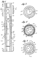
- FIG. 1 is a sectional elevation of the invention mounted in a drill string in a well bore;
- FIG. 2 is a view taken on line 2-2 of FIG. 1;
- FIG. 3 is a view taken on line 3-3 of FIG. 1;
- FIG. 4 is a view taken on line 4-4 of FIG. 1;
- FIG. 5 is an enlarged sectional elevation taken on line 5-5 of FIG. 4, and in which the housing is not shown;
- FIG. 6 is an enlarged sectional elevation taken on line 6-6 of FIG. 4;
- FIG. 7 is an enlarged view taken in the area of 7-7 of FIG. 1;
- FIG. 8 is an enlarged view taken in the area of 8-8 of FIG. 1;
- FIG. 9 is an end view of the wear ring;
- FIG. 10 is a view taken on line 10-10 of FIG. 9;
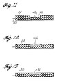
- FIG. 11 is a schematic sectional elevation of a portion of the sleeve before the application of electrode material;
- FIG. 12 is a view similar to FIG. 11 showing electrode material applied to the sleeve; and
- FIG. 13 is a view similar to FIGS. 11 and 12 showing the electrode in a finished condition.
- Referring to FIG. 1, an elongated, cylindrical,
hollow sleeve 20 makes a close slip-fit over alower section 22 of an elongated, generallycylindrical housing 24 having a centrallongitudinal bore 26 extending through it. The housing includesupper section 27 of larger outside diameter than thelower section 22, so that an annular, downwardly facing (as viewed in FIG. 1)shoulder 28 is formed where thelarger section 27 steps down to the smallest diameter oflower section 22. The housing is part of a drill string 29 disposed in a well bore 30. - An
annular wear ring 31 makes a close slip-fit around thesmaller diameter section 22 of the housing so that the upper surface of the wear ring bears againstshoulder 28. Thelower surface 32 of the wear ring slopes downwardly and outwardly to rest on a matching surface at the upper end of the sleeve. - An
upper electrode ring 34 is disposed in an upper circumferential and outwardly openinggroove 36 in the outer surface of the sleeve. A lowerannular electrode 38 is disposed in a lower circumferential and outwardly openinggroove 40 in the outer surface of the sleeve. - The upper and lower electrodes are connected by separate electrical conductors 42 (one such conductor is shown in FIGS. 11-13) in a
cable 44, which extends up through the insulated sleeve and acable tunnel 46 formed through the wear ring and the wall of the housing. - The upper end of the cable is connected to a power and
instrument package 48, which includes an electrical power source (not shown) and appropriate equipment (not shown) for generating, measuring, and recording signals developed in response to various physical characteristics of the adjacent formation in the well bore. The power and instrument package is secured in the center of thecentral bore 26 of the housing by three equally spaced and radially extendingspiders 50 secured at their inner ends to the power and instrument package. The outer ends of the spiders bear against the interior surface of the bore through the housing. The lower edges of the spiders rest on an annular and upwardly facing internal shoulder 52 formed within thebore 26 in the housing. As shown in FIGS. 1 and 2, the cable tunnel includes ahorizontal section 54, which extends from the power and instrument package through one of the spiders to join the upper end of the vertical portion of the cable tunnel in the wall of the housing. - The lower end of the insulated sleeve has a downwardly and inwardly extending annular surface, which rests on a matching
surface 62 on the upper end of atorque tube 64, which makes a close slip-fit around the lower portion of the housing. The lower end of the torque tube rests on an upwardly facingannular shoulder 66 at the upper end of adrill collar section 68, into which the lower end of the housing is threaded. The upper end of the housing is threaded onto the lower end of a section of drill collar 70 in the drill string. - As shown in FIG. 3, the insulating sleeve includes four equally spaced, inwardly projecting, and longitudinally extending
splines 72, which each fit into a respective matching outwardly opening and longitudinally extendinggroove 74 in the outer surface of the housing. The splines on the insulated sleeve extend for the full length of the sleeve. The grooves in the exterior surface of the housing extend from about the midpoint of the wear ring to the lower end of the torque tube, which has four equally spaced, inwardly projecting splines 76 (FIG. 4) which extend longitudinally for the length of the torque tube and fit into the housing grooves. - In effect, the
splines 72 on the sleeve form a separatelongitudinally extending groove 77 between adjacent splines, and thegrooves 74 in the housing form a separate longitudinally extendingspline 78 between adjacent grooves. - The bottom surfaces of the grooves and the top surfaces of the splines of the sleeve and the housing taper inwardly away from the shoulder to facilitate assembly and disassembly of the sleeve on the housing. The amount of taper can vary over a wide range, but we have found that a relatively slight taper, say, about 1/8" in 13 feet (i.e. about 3.2 mm in 4 m), is adequate to provide an easy, but close slip-fit of the sleeve on the housing.
- The
splines 76 on the torque tube form a separatelongitudinally extending groove 79 between adjacent splines. The grooves and splines of the sleeve and torque tube make a close slip-fit with the grooves and splines of the housing so the torque tube is firmly supported against rotation relative to the housing, but is easily moved longitudinally when necessary. - Referring to FIG. 5, which is a view taken on line 5-5 of FIG. 4 (with the housing not shown), a
wire retaining ring 80 is disposed in four inwardly opening,circumferential grooves 82 formed in the lower ends of the torque splines 76, so the wire is secured under an outwardly extending and downwardly facing shoulder 84 (FIG. 6), where the o.d. of the housing is reduced for a short, vertical section 86 adjacent the upper end of the lowerdrill collar section 68. The retainingring 80 prevents the torque tube from sliding upwardly along the housing if the insulated sleeve should be worn away during drilling operations. - Referring to FIG. 7, the wear ring is prevented from sliding downwardly (if the insulated sleeve should be worn away during drilling operations) by a
bolt 90 threaded into the housing wall to project outwardly into the inner end of abore 92 extending radially through the wear ring wall. More than one such bolt can be used, if desired. Three inwardly and longitudinally extending splines 93 (FIGS. 9 and 10) on the inner surface of the lower half of the wear ring each fit into arespective groove 74 in the outer surface of the housing to prevent the wear ring from rotating on the housing, and yet leave the wear ring free to slide longitudinally when thebolt 90 is removed. - As shown best in FIG. 8, the upper end of the
electrical cable 44 extends from the upper end of the insulating sleeve into a longitudinally extending slot 94 (FIGS. 9 and 10) in the interior surface of the wear ring. As shown in FIG. 9, theslot 94 is spaced 90° from two of thewear ring splines 93, which are each spaced 90° from the third spline. Thus, the three wear ring splines each form a separaterespective groove 95 between adjacent splines, the groove which includesslot 94 being twice as wide as the other two. Accordingly, the grooves and splines of the wear ring make a close slip-fit with all four of the splines on the housing, but with only three of the grooves in the housing because ofwear ring slot 94. This is adequate support to restrain the wear ring from rotating relative to the housing. - The upper end of the cable carries a
connector plug 96, (FIG. 8), which releasably fits into asocket 98 sealed in the lower end of the vertical portion of thecable tunnel 46 in the wall of the housing to prevent incursion of drilling fluid into the power and instrument package. Theplug 96 is provided with suitable sealing means (not shown), which may be of conventional construction, to prevent incursion of high-pressure fluids from the well bore into the electrical connections made by the plug with the socket. - The material which forms the insulated sleeve must withstand high temperatures and shock. It must also have reasonably good wear resistance to the abrasive conditions encountered during the drilling of most wells, and it must have high electrical resistivity to avoid unacceptable leakage between the drill string and electrodes or other sensing devices on the sleeve. These requirements are met by forming the insulating sleeve from the glass fibers and epoxy resin, which includes particles of abrasion-resistant material, such as aluminum oxide sold under the registered trademark "Carborundum" of Harbison-Carborundum Corp. of Niagara Falls, New York, U.S.A. US―A―3,072,843 to Clements et al. describes the use of such materials to form an electrode sleeve on a drill pipe.
- We have prepared suitable insulating sleeves by wrapping glass fibers coated with epoxy resin and Carborundum particles around a mandrel (not shown) which matches the surfaces of the portion of the housing around which the insulated sleeve is to fit. During the wrapping operation, the appropriate electrical conductors are embedded in the wall of the insulating sleeve as it is formed. The top and bottom surfaces of the splines and grooves of the mandrel taper toward one end to match that of the housing. Accordingly, after the resin has cured, the formed sleeve can be easily slipped off the mandrel, and the internal surfaces of the sleeve are tapered to match those on the housing.
- The principal steps in making an electrode sleeve assembly, say, useful for electric well logging, are shown in FIGS. 11-13. Outwardly opening, circumferential grooves 40 (only one groove is shown in FIGS. 11-13) are formed in the outer surface of the sleeve to reach the end of one of the
conductors 42 embedded in the sleeve wall during the production of the sleeve. The end of the conductor is raised into the groove and stripped of insulation to expose bare metal. - As shown in FIG. 12, a
metallic conductor material 100 is deposited in the prepared groove to invest the exposed end of the conductor. The deposited metal may be sprayed into place by the well-known Metco process. It may also be electrodeposited, accumulated by vapor deposition, or any combination of such processes. Spray deposition is presently preferred. As shown in FIG. 13, the deposited metal is smoothed so that its outer surface is flush with the outer surface of the sleeve, leaving anannular electrode 38. - In using the replaceable sleeve of this invention, it is assembled as shown in FIG. 1, so that it is firmly supported on the housing and clamped between the wear ring at its upper end and the torque tube at its lower end. The torque tube is made of steel of sufficient strength to accept the wear and stress imposed by conventional tongs (not shown) when the housing is threaded into, or out of, a drill collar. The
annular shoulder 66 on the drill collar holds the torque tube in a snug fit against the sleeve, which is thereby placed in slight, but firm, compression for the drilling operation. The torque tube accepts all of the mechanical wear and tear in connecting or disconnecting the housing in the drill string. - Although the insulated sleeve can vary in length for different uses, for most well logging operations, it will be between about 2 and about 15 feet (i.e. between about 61 cm and about 4.57 m) long. If it is relatively short, say, only a foot or two (i.e. about 30 cm or 61 cm), the torque tube may be omitted, letting the lower end of the electrode sleeve bear directly against the
shoulder 66 of thedrill collar section 68. Under these circumstances, the tongs, normally used to make up or break apart drill string, would have to be shifted upwardly from their normal position to engage the housing above the insulating sleeve. If the sleeve is more than a few feet (i.e. a few thirties cm) long, it normally would not be feasible to raise the tongs sufficiently high to avoid contact with the sleeve. Accordingly, the torque tube is almost always required for practical operations. - Although the insulating sleeve in the specific embodiment described above is built to facilitate measuring the electrical resistivity of formations traversed by the well bore, the sleeve can be provided with other sensing devices for measuring other characteristics of the formations. For example, piezoelectric crystals can be embedded in the sleeve to measure acoustical properties, or other sensors can be used to measure pressure, temperature, or borehole deviation during the drilling.
- An important advantage of this invention is that the insulating sleeve can be quickly and easily assembled on, or removed from, the primary housing. This is essential in most drilling operations where delays in handling equipment at a drilling rig are expensive and sometimes dangerous.
- If the insulated sleeve is damaged or worn away during drilling operations, the wear ring protects the
annular shoulder 28 on the housing from damage. The retaining ring in the lower end of the torque tube prevents the tube from sliding up and down the housing, avoiding possible damage to the housing or the wear ring. - In the course of prolonged use, the wear ring may eventually be so worn or damaged that it no longer protects the shoulder or holds the insulated sleeve in the desired position on the housing. The wear ring is then easily removed and replaced by a new one.
- If desired, a second wear ring of appropriate size and shape can be disposed between the torque tube and the lower end of the insulated sleeve to prevent damage to the upper end of the torque tube when the insulated sleeve is worn away.
- The insulated sleeve is easily replaced by simply slipping it off the lower end of the housing after the housing is removed from the
drill collar section 68, and the torque tube is slipped off the lower end of the housing. The electrical plug 96 (FIG. 8) is disconnected by removing the bolt 90 (FIG. 7) from thebore 92 in the wear ring wall so the wear ring and insulating sleeve can be lowered a few inches (i.e. a few 2.54 cm) to provide access to theplug 96, which is then removed. A similar plug (not shown) on a replacement sleeve (not shown) is connected to thesocket 98 and sealed thereto by appropriate means (not shown). The wear ring is then raised back to its position againstshoulder 28 on the primary housing and locked in place by inserting thebolt 90, which has an internal hex socket 101 to facilitate screwing the bolt into and out of the housing wall. The torque tube is slipped over the lower end of the housing to the position shown in FIG. 1. The tongs are applied to the torque tube, and the lower end of the housing is threaded into the upper end of thedrill collar section 68 until the torque tube, insulated sleeve, and wear ring are snugly fitted together as shown in FIG. 1. - With the apparatus assembled as shown in FIG. 1, it can be used to log the electrical resistivity of formations traversed as the well is drilled. The logging information can be either recorded with equipment (not shown) in the power and instrument package, or it can be transmitted to the surface during drilling by generating coded pressure pulses in the drilling fluid, such as described in US-A-3,964,556 to Gearhart et al. or US-A-4,078,620 to Westlake et al.
- From the foregoing description, it will be apparent that this invention provides an insulated sleeve which can be quickly and snugly fitted around a portion of the drill string so the sleeve is not rotatable relative to the drill string, and so the sleeve can be quickly slipped off the drill string, when required.
Claims (19)
characterized by the fact that it further comprises:
3-Apparatus according to claim 1 in which the housing (24) includes an outwardly extending shoulder (28) adjacent one end of the sleeve (20) to prevent the sleeve (20) from sliding longitudinally relative to the housing (24) in one direction.
characterized by the fact that, for making an electrode assembly adapted to slide on and off a drill-string (29), the mandrel has an exterior surface which converges toward one end so the sleeve (20) is formed with an internal converging surface matching the external surface of the mandrel, and the method further comprises the steps of:
- between steps b and e:
- after step e:
characterized by the fact that, for making a logging assembly adapted to slide on and off a drill string (29), the mandrel has an exterior surface which converges toward one end so the sleeve (20) is formed with an internal converging surface matching the external surface of the mandrel and the method further comprises, after step e, the step of:
Applications Claiming Priority (1)
| Application Number | Priority Date | Filing Date | Title |
|---|---|---|---|
| PCT/US1981/001326 WO1983001336A1 (en) | 1981-10-01 | 1981-10-01 | Well logging apparatus and method for making same |
Publications (3)
| Publication Number | Publication Date |
|---|---|
| EP0090800A1 EP0090800A1 (en) | 1983-10-12 |
| EP0090800A4 EP0090800A4 (en) | 1985-09-16 |
| EP0090800B1 true EP0090800B1 (en) | 1988-01-07 |
Family
ID=22161459
Family Applications (1)
| Application Number | Title | Priority Date | Filing Date |
|---|---|---|---|
| EP81902874A Expired EP0090800B1 (en) | 1981-10-01 | 1981-10-01 | Well logging apparatus and method for making same |
Country Status (6)
| Country | Link |
|---|---|
| EP (1) | EP0090800B1 (en) |
| AU (1) | AU7801981A (en) |
| DE (1) | DE3176602D1 (en) |
| GB (2) | GB2119521B (en) |
| NO (1) | NO831886L (en) |
| WO (1) | WO1983001336A1 (en) |
Families Citing this family (4)
| Publication number | Priority date | Publication date | Assignee | Title |
|---|---|---|---|---|
| US4483393A (en) * | 1982-09-24 | 1984-11-20 | Exploration Logging, Inc. | Well logging apparatus and method for making same |
| US4618828A (en) * | 1982-11-12 | 1986-10-21 | Teleco Oilfield Services Inc. | Insulating segment for a drill string electrode structure |
| GB2146127A (en) * | 1983-08-31 | 1985-04-11 | Exxon Production Research Co | Protective sheath in induction logging tool |
| DK165307C (en) * | 1987-06-04 | 1993-03-22 | Kurt Ingvard Soerensen | PROBLEM FOR MEASURING THE ELECTRICAL FORMATION RESISTANCE IN EARTH |
Family Cites Families (7)
| Publication number | Priority date | Publication date | Assignee | Title |
|---|---|---|---|---|
| US2096359A (en) * | 1936-01-14 | 1937-10-19 | Geophysical Res Corp | Apparatus for subsurface surveying |
| US3072843A (en) * | 1957-08-13 | 1963-01-08 | Texaco Inc | Abrasion resistant coating suitable for borehole drilling apparatus |
| US3134069A (en) * | 1959-01-30 | 1964-05-19 | Texaco Inc | Well logging apparatus having detector means in a rotatable casing mounted within a drill string for simultaneous drilling and logging |
| US3408561A (en) * | 1963-07-29 | 1968-10-29 | Arps Corp | Formation resistivity measurement while drilling, utilizing physical conditions representative of the signals from a toroidal coil located adjacent the drilling bit |
| US3377549A (en) * | 1964-12-23 | 1968-04-09 | Arps Corp | Coil assembly structure and mounting forming an annular chamber to be mounted and sealed on a drill collar |
| DE2638799C3 (en) * | 1976-08-27 | 1981-12-03 | Ibm Deutschland Gmbh, 7000 Stuttgart | Process for improving the adhesion of metallic conductor tracks to polyimide layers in integrated circuits |
| US4286217A (en) * | 1979-02-01 | 1981-08-25 | Schlumberger Technology Corporation | Device for electrode-type electrical logging tools and tool incorporating said device |
-
1981
- 1981-10-01 GB GB08311281A patent/GB2119521B/en not_active Expired
- 1981-10-01 AU AU78019/81A patent/AU7801981A/en not_active Abandoned
- 1981-10-01 EP EP81902874A patent/EP0090800B1/en not_active Expired
- 1981-10-01 WO PCT/US1981/001326 patent/WO1983001336A1/en active IP Right Grant
- 1981-10-01 DE DE8181902874T patent/DE3176602D1/en not_active Expired
- 1981-10-01 GB GB08503930A patent/GB2153088B/en not_active Expired
-
1983
- 1983-05-27 NO NO831886A patent/NO831886L/en unknown
Also Published As
| Publication number | Publication date |
|---|---|
| GB8503930D0 (en) | 1985-03-20 |
| GB8311281D0 (en) | 1983-06-02 |
| AU7801981A (en) | 1983-04-27 |
| EP0090800A1 (en) | 1983-10-12 |
| GB2119521B (en) | 1986-02-05 |
| DE3176602D1 (en) | 1988-02-11 |
| GB2153088A (en) | 1985-08-14 |
| GB2119521A (en) | 1983-11-16 |
| NO831886L (en) | 1983-05-27 |
| WO1983001336A1 (en) | 1983-04-14 |
| EP0090800A4 (en) | 1985-09-16 |
| GB2153088B (en) | 1986-03-19 |
Similar Documents
| Publication | Publication Date | Title |
|---|---|---|
| US4494072A (en) | Well logging apparatus with replaceable sensor carrying insulating sleeve disposed in rotation restrained position around a drill string | |
| US4483393A (en) | Well logging apparatus and method for making same | |
| US3807502A (en) | Method for installing an electric conductor in a drill string | |
| US3876972A (en) | Kelly | |
| US4496174A (en) | Insulated drill collar gap sub assembly for a toroidal coupled telemetry system | |
| US4348672A (en) | Insulated drill collar gap sub assembly for a toroidal coupled telemetry system | |
| US8648733B2 (en) | Electromagnetic telemetry assembly with protected antenna | |
| US4997044A (en) | Apparatus for generating hydraulic shock waves in a well | |
| US5495755A (en) | Slick line system with real-time surface display | |
| US5131464A (en) | Releasable electrical wet connect for a drill string | |
| US20040113808A1 (en) | Signal connection for a downhole tool string | |
| US4356629A (en) | Method of making well logging apparatus | |
| AU6118596A (en) | Subsurface signal transmitting apparatus | |
| CA2549541C (en) | Mass isolation joint for electrically isolating a downhole tool | |
| EP2203620B1 (en) | Structure for wired drill pipe having improved resistance to failure of communication device slot | |
| CN110397407B (en) | Double-shoulder conductive drill rod | |
| US6208265B1 (en) | Electromagnetic signal pickup apparatus and method for use of same | |
| JP2007518906A (en) | Drill column for deep well and drill pipe and bush for the drill column | |
| EP0090800B1 (en) | Well logging apparatus and method for making same | |
| CA1168572A (en) | Well logging apparatus and method for making same | |
| JPS59225500A (en) | Signal transmitter |
Legal Events
| Date | Code | Title | Description |
|---|---|---|---|
| PUAI | Public reference made under article 153(3) epc to a published international application that has entered the european phase |
Free format text: ORIGINAL CODE: 0009012 |
|
| AK | Designated contracting states |
Kind code of ref document: A1 Designated state(s): DE FR NL |
|
| 17P | Request for examination filed |
Effective date: 19830818 |
|
| 17Q | First examination report despatched |
Effective date: 19860716 |
|
| GRAA | (expected) grant |
Free format text: ORIGINAL CODE: 0009210 |
|
| AK | Designated contracting states |
Kind code of ref document: B1 Designated state(s): DE FR NL |
|
| PG25 | Lapsed in a contracting state [announced via postgrant information from national office to epo] |
Ref country code: NL Effective date: 19880107 |
|
| REF | Corresponds to: |
Ref document number: 3176602 Country of ref document: DE Date of ref document: 19880211 |
|
| ET | Fr: translation filed | ||
| NLV1 | Nl: lapsed or annulled due to failure to fulfill the requirements of art. 29p and 29m of the patents act | ||
| PGFP | Annual fee paid to national office [announced via postgrant information from national office to epo] |
Ref country code: DE Payment date: 19881018 Year of fee payment: 8 |
|
| PLBE | No opposition filed within time limit |
Free format text: ORIGINAL CODE: 0009261 |
|
| STAA | Information on the status of an ep patent application or granted ep patent |
Free format text: STATUS: NO OPPOSITION FILED WITHIN TIME LIMIT |
|
| 26N | No opposition filed | ||
| PG25 | Lapsed in a contracting state [announced via postgrant information from national office to epo] |
Ref country code: FR Effective date: 19900629 |
|
| PG25 | Lapsed in a contracting state [announced via postgrant information from national office to epo] |
Ref country code: DE Effective date: 19900703 |
|
| REG | Reference to a national code |
Ref country code: FR Ref legal event code: ST |