EP0090519A2 - Behälter - Google Patents
Behälter Download PDFInfo
- Publication number
- EP0090519A2 EP0090519A2 EP19830301230 EP83301230A EP0090519A2 EP 0090519 A2 EP0090519 A2 EP 0090519A2 EP 19830301230 EP19830301230 EP 19830301230 EP 83301230 A EP83301230 A EP 83301230A EP 0090519 A2 EP0090519 A2 EP 0090519A2
- Authority
- EP
- European Patent Office
- Prior art keywords
- divider
- storage container
- compartments
- housing
- main receptacle
- Prior art date
- Legal status (The legal status is an assumption and is not a legal conclusion. Google has not performed a legal analysis and makes no representation as to the accuracy of the status listed.)
- Withdrawn
Links
- 238000003860 storage Methods 0.000 claims abstract description 19
- 238000010586 diagram Methods 0.000 claims description 7
- 238000007789 sealing Methods 0.000 claims description 5
- 230000001419 dependent effect Effects 0.000 claims 1
- 230000000007 visual effect Effects 0.000 claims 1
- 238000004519 manufacturing process Methods 0.000 description 4
- 238000010923 batch production Methods 0.000 description 3
- 238000000034 method Methods 0.000 description 3
- 239000000463 material Substances 0.000 description 2
- 238000003908 quality control method Methods 0.000 description 2
- 229920005439 Perspex® Polymers 0.000 description 1
- 230000015556 catabolic process Effects 0.000 description 1
- 230000002708 enhancing effect Effects 0.000 description 1
- 239000006260 foam Substances 0.000 description 1
- 238000007689 inspection Methods 0.000 description 1
- 230000004048 modification Effects 0.000 description 1
- 238000012986 modification Methods 0.000 description 1
- 229920003023 plastic Polymers 0.000 description 1
- 239000004033 plastic Substances 0.000 description 1
- 239000004926 polymethyl methacrylate Substances 0.000 description 1
Images
Classifications
-
- H—ELECTRICITY
- H05—ELECTRIC TECHNIQUES NOT OTHERWISE PROVIDED FOR
- H05K—PRINTED CIRCUITS; CASINGS OR CONSTRUCTIONAL DETAILS OF ELECTRIC APPARATUS; MANUFACTURE OF ASSEMBLAGES OF ELECTRICAL COMPONENTS
- H05K13/00—Apparatus or processes specially adapted for manufacturing or adjusting assemblages of electric components
- H05K13/0053—Arrangements for assisting the manual mounting of components, e.g. special tables or light spots indicating the place for mounting
Definitions
- This invention relates to containers for storing and/or transporting articles, such as, electrical components, and is especially, but not exclusively related to such containers for controlling the work in progress (WIP) in the assembly and batch production of small electronic products, for instance, printed circuit board (PCB) modules.
- WIP work in progress
- PCB printed circuit board
- the invention provides a container for storing articles of different sizes, comprising a plurality of storage compartments, at least one adjacent pair of the compartments being separated by a divider which is moveable with respect to a main receptacle housing, whereby each of said at least one pair of adjacent compartments can be adjusted in size to accommodate articles of differing sizes.
- the receptacle housing is elongate has a generally U-shaped cross section, in which case, the cross section of each compartment divider is also semi-circular, with the dividers being adjustably moveable axially with respect to the housing.
- Each moveable divider can be fixed at any required position within the housing, once it has been moved with respect thereto to provide a suitably sized compartment on each side thereof.
- the receptacle housing is preferably provided with a lid of which at least part is pivotable with respect to the housing to provide access to each compartment therein.
- the or each divider may be provided with sealing means to prevent articles stored in each compartment from being transferred accidentally to another compartment and, in addition, the lid may also have sealing means which, when the lid is closed, retains any articles stored in the container in their respective compartments.
- the invention can provide a container having two receptacle housings which are hinged together between open and closed positions, such that, in the closed position, the respective compartments are totally enclosed with their lids confronting each other.
- This provides a very suitable container for transportation purposes and, for this reason can be provided with a carrying handle.
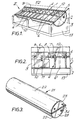
- an electronic component container 1 comprises a receptacle housing 2 of semi-circular cross-section, which is closed at each end by a correspondingly-dimensioned semi-circular end wall 3. Between each end wall 3 of the receptacle housing 2, extends a rigid rod 4 of circular cross-section, the ends of the rod being located fixedly in holes 5 in respective end walls 3.
- dividers 6 Slidably mounted upon the rod 4 is a plurality of dividers 6 which define respective compartments therebetween for receiving electronic components (not shown) to be assembled upon a printed circuit board (also not shown).
- Each of these dividers 6 can be located at a desired position along the length of the rod 4, such that adjacent pairs of dividers define therebetween a compartment of predetermined capacity for receiving a given number of electronic components of a certain size.
- the slidable adjustment of the dividers 6 with respect to the rigid rod 4 is shown clearly in Fig 2, wherein an alternative position for either of the two right hand dividers is shown in chain-dotted lines at 6'.
- Each divider 6 can be secured in the desired position upon the rod 4 by means of a locking arrangement comprising a threaded, split tube portion 7 which is fixed to the divider 6 and extends annularly and axially with respect to the rod 4 and upon which is threaded a tightening nut 8.
- a locking arrangement comprising a threaded, split tube portion 7 which is fixed to the divider 6 and extends annularly and axially with respect to the rod 4 and upon which is threaded a tightening nut 8.
- the receptacle housing 2 is provided with a transparent, perspex lid of which a first part 9 is fixed and a second part 10 is pivotable with respect thereto between open and closed positions, by means of interconnecting hinge elements 11.
- the confronting surfaces and/or edges of the receptacle housing 2, the compartment dividers 6 and the pivotable lid part 10 are sealed by means of plastics foam strip material 12 which closes any gaps between these components of the container 1 to prevent electronic components in one of the compartments from being transferred accidentally to another of the compartments during transit.
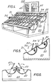
- the container 1 is mounted upon a stand 13 such that its upper flat surface is inclined towards an operative who will be able to view the components in each compartment through the transparent lid parts 9,10.
- the inner arcuate surface of the receptacle housing 2 permits ready removal of components from their respective compartments, with the pivotable lid part 10 in its open position.
- the lid can be in one part which is pivotable with respect to the receptacle housing 2, rather than in two parts 9, 10, as shown in this particular embodiment.
- this electronic component container 21 comprises 2 receptacle housings 22 of semi-circular cross-section which are hinged together by means of a pair of hinge members 34 attached to respective pairs of end walls 23.
- Each receptacle housing 22 is substantially identical to the container 1 having a single receptacle housing 2, described above with reference to Figs 1 and 2.
- each housing 22 is mounted upon a stand 33, with the upper face of each housing 22 inclined towards an operative position.
- both lid parts 30 are pivotable with respect to their associated fixed lid part 29 in the same direction, as indicated by the arrows 35, between their open and closed positions.
- the pivotable lid parts 40 are moveable in opposite directions, as indicated by the arrows 41,42, between their respective open and closed positions.
- the two receptacle housings 42 are mounted in the associated stand 43, such that the upper sides of the housings are inclined in opposite directions, whereby this arrangement can be used by two operatives in tandem, that is to say, facing each other.
- the stand 33 is provided with two assembly diagrams 45 which correspond to the circuit to be assembled from the electronic components in the respective compartments by an operative.
- a series of light emitting diodes (not shown) are housed in the stand 13 which supports the electronic component container 21 on a work bench and a further series of light emitting diodes (also not shown) are plugged in to corresponding positions on the assembly diagrams 45.
- the light emitting diode associated with each compartment is lit in turn, as is the corresponding diode on the diagram 45, the sequential operation of the light emitting diodes along the compartments being switch-operated by the operative.
- each divider could be provided with means, such as, a projecting lug slidably engaged in a corresponding groove or channel in the inner surface of the receptacle housing.
- this slidable engagement between the dividers and receptacle housing is frictional, whereby any locking arrangement, such as, the threaded, split tube portion 7 and associated tightening nut 8 can be eliminated.
- a suitable form of locking arrangement could be provided, if necessary.
- inventive container can be used for purposes other than that described above, for instance, for general storage purposes, particularly in the do-it-yourself field.
Landscapes
- Engineering & Computer Science (AREA)
- Manufacturing & Machinery (AREA)
- Microelectronics & Electronic Packaging (AREA)
- Packaging Frangible Articles (AREA)
Applications Claiming Priority (2)
| Application Number | Priority Date | Filing Date | Title |
|---|---|---|---|
| GB8209067 | 1982-03-27 | ||
| GB8209067A GB2118141A (en) | 1982-03-27 | 1982-03-27 | Partitioned storage containers |
Publications (1)
| Publication Number | Publication Date |
|---|---|
| EP0090519A2 true EP0090519A2 (de) | 1983-10-05 |
Family
ID=10529337
Family Applications (1)
| Application Number | Title | Priority Date | Filing Date |
|---|---|---|---|
| EP19830301230 Withdrawn EP0090519A2 (de) | 1982-03-27 | 1983-03-08 | Behälter |
Country Status (2)
| Country | Link |
|---|---|
| EP (1) | EP0090519A2 (de) |
| GB (1) | GB2118141A (de) |
Family Cites Families (5)
| Publication number | Priority date | Publication date | Assignee | Title |
|---|---|---|---|---|
| GB510142A (en) * | 1939-02-15 | 1939-07-27 | William Walsh | Improvements in or relating to internal fittings for hollow containers |
| GB1105801A (en) * | 1965-08-12 | 1968-03-13 | Akro Mills Inc | Plastics drawer assembly |
| FR1507180A (fr) * | 1966-07-04 | 1967-12-29 | Perfectionnement aux boîtes à compartiments variables pour le classement d'objets tels que des pièces mécaniques | |
| US3572536A (en) * | 1969-04-14 | 1971-03-30 | Cramer Ind Inc | Adjustable card file |
| AT356316B (de) * | 1976-09-17 | 1980-04-25 | Hrovat Horst Mag Pharm | Aufbewahrungskasten fuer sortiert aufzube- wahrende kleinteile |
-
1982
- 1982-03-27 GB GB8209067A patent/GB2118141A/en not_active Withdrawn
-
1983
- 1983-03-08 EP EP19830301230 patent/EP0090519A2/de not_active Withdrawn
Also Published As
| Publication number | Publication date |
|---|---|
| GB2118141A (en) | 1983-10-26 |
Similar Documents
| Publication | Publication Date | Title |
|---|---|---|
| US6068437A (en) | Automated laboratory specimen organizer and storage unit | |
| EP0961128B1 (de) | Modulare Einrichtung zur mechanischen Befestigung und automatischen Handhabung von Leiterplattenbaugruppen für eine automatische Testeinrichtung | |
| DK0732051T3 (da) | Fodringsstation til kæledyr | |
| ATE111844T1 (de) | Verwandelbarer versand- und endverbraucherkarton. | |
| EP0777202A3 (de) | Gerät zur Aufbewahrung und Ausgabe von Nahrungsmitteln | |
| JPS567834A (en) | Apparatus for accumulating tray* box or similar container loaded with goods such as eggs | |
| EP0365828A3 (de) | Probenhalterung für Probengefässe | |
| DE3562930D1 (en) | Modular apparatus for cell culture | |
| ES292970U (es) | Cassette para soportar una pluralidad de recipientes de muestra | |
| ES8304747A1 (es) | "perfeccionamientos en los dispositivos para el transporte de circuitos impresos". | |
| EP1380842A3 (de) | Probenbehälteranordnung | |
| DE69201427D1 (de) | Vorrichtung zum Laden und Entladen von Eierbehältnissen. | |
| DE60303124T2 (de) | Verfahren zur formatumstellung in einer verpackungsmaschine | |
| DE3473573D1 (en) | Device for transferring components, in particular integrated chips, from an input tray to an output tray | |
| EP0090519A2 (de) | Behälter | |
| ATE100029T1 (de) | Halter fuer getraenkedosen als teil eines in ein kraftfahrzeug einsetzbaren aufbewahrungssystems. | |
| DK216088D0 (da) | Indretning til fjernelse af beholdere fra en stabel samt et konditioneringsapparat, der er forsynet med en saadan indretning | |
| US4887717A (en) | Packaging with a gauge or tool formed from the package | |
| CA2449719C (en) | Linear conveyor system | |
| US5195641A (en) | Sorting line for processing envelopes, particularly for photographic laboratories | |
| DE3061000D1 (en) | Sorting apparatus for grading piece goods | |
| EP0138576A2 (de) | Magnetbandkassettenbehälter | |
| US6384361B1 (en) | Error free trays for bin sorting | |
| ZA816191B (en) | A tray for storing and classifying slides and a viewer for slides disposed in such trays | |
| SU1143663A1 (ru) | Многофункциональна кассета |
Legal Events
| Date | Code | Title | Description |
|---|---|---|---|
| PUAI | Public reference made under article 153(3) epc to a published international application that has entered the european phase |
Free format text: ORIGINAL CODE: 0009012 |
|
| AK | Designated contracting states |
Designated state(s): AT BE CH DE FR GB IT LI LU NL SE |
|
| STAA | Information on the status of an ep patent application or granted ep patent |
Free format text: STATUS: THE APPLICATION IS DEEMED TO BE WITHDRAWN |
|
| 18D | Application deemed to be withdrawn |
Effective date: 19851001 |
|
| RIN1 | Information on inventor provided before grant (corrected) |
Inventor name: HILSDEN, JOHN SIDNEY |