EP0090411B1 - Submerged motor pump assembly - Google Patents
Submerged motor pump assembly Download PDFInfo
- Publication number
- EP0090411B1 EP0090411B1 EP83103116A EP83103116A EP0090411B1 EP 0090411 B1 EP0090411 B1 EP 0090411B1 EP 83103116 A EP83103116 A EP 83103116A EP 83103116 A EP83103116 A EP 83103116A EP 0090411 B1 EP0090411 B1 EP 0090411B1
- Authority
- EP
- European Patent Office
- Prior art keywords
- spring
- motor
- tube
- fluid
- tank
- Prior art date
- Legal status (The legal status is an assumption and is not a legal conclusion. Google has not performed a legal analysis and makes no representation as to the accuracy of the status listed.)
- Expired
Links
Images
Classifications
-
- F—MECHANICAL ENGINEERING; LIGHTING; HEATING; WEAPONS; BLASTING
- F04—POSITIVE - DISPLACEMENT MACHINES FOR LIQUIDS; PUMPS FOR LIQUIDS OR ELASTIC FLUIDS
- F04D—NON-POSITIVE-DISPLACEMENT PUMPS
- F04D13/00—Pumping installations or systems
- F04D13/02—Units comprising pumps and their driving means
- F04D13/06—Units comprising pumps and their driving means the pump being electrically driven
- F04D13/08—Units comprising pumps and their driving means the pump being electrically driven for submerged use
- F04D13/10—Units comprising pumps and their driving means the pump being electrically driven for submerged use adapted for use in mining bore holes
-
- H—ELECTRICITY
- H02—GENERATION; CONVERSION OR DISTRIBUTION OF ELECTRIC POWER
- H02K—DYNAMO-ELECTRIC MACHINES
- H02K5/00—Casings; Enclosures; Supports
- H02K5/04—Casings or enclosures characterised by the shape, form or construction thereof
- H02K5/12—Casings or enclosures characterised by the shape, form or construction thereof specially adapted for operating in liquid or gas
- H02K5/132—Submersible electric motors
Definitions
- the present invention relates to a motor-pump unit immersed in a well in which the motor part is filled with a fluid protecting it from the outside environment and comprising a dynamic sealing system between the pump part, driven by said motor part and in contact with the external environment, and the driving part filled with said fluid, an expandable compensation reservoir, communicating with the driving part, being situated under said driving part, at its opposite end with respect to said dynamic seal, beyond the end of the drive shaft, said expansion tank being subjected to the pressure of the external medium and to the force of a spring compression device bearing, on the one hand against a fixed part, linked to the carcass of the driving part and closing it at its lower part and on the other hand against said expandable reservoir, ensuring an overpressure of the fluid inside the driving part with respect to the outside environment.
- a tdl motor-pump group is for example described in document US-A-3369137.
- the expandable overpressure tank avoids pollution of the internal environment of the drive part.
- the motor-pump unit is generally constituted by an assembly of several very long motors, for example three motors of eight to nine meters in length each, of small diameter, surmounted by several coupled pumps, one obtains during the descent, and because of the expansion of the tank, due to the rise in temperature, unacceptable overpressures which make unusable this kind of expandable tanks.
- the present invention aims to overcome this drawback and to allow valid use of an expandable tank under pressure in very deep wells at high temperature.
- the subject of the invention is therefore a motor-pump unit as specified above, which is characterized in that said spring compression device comprises a first spring and a second spring, the forces of which are added, all based on both on said expandable reservoir, said second spring comprising a release device comprising a tube, mounted on a support rod against the reservoir, said second spring pressing against a sleeve abutting against said tube and the latter being secured of the rod by means of a row of balls held in a groove in the rod and in housings of the tube by a sleeve, the compression of said second spring to a bearing stop for said sleeve allowing, by sliding of the sleeve on the tube, the release of the balls from said groove and the sliding of the tube on the rod thus discharging said second spring when its arrow reaches a predetermined value.
- said spring compression device comprises a first spring and a second spring, the forces of which are added, all based on both on said expandable reservoir
- said second spring comprising a
- the support of the two springs against said expandable reservoir is produced by means of a part bearing on the reservoir by the interposition of a ball stop making said part free to rotate.
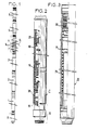
- FIG. 1 shows a motor pump assembly consisting of a number of assembled modules. As shown, this assembly comprises three motors 1, 2 and 3, a gas separator 4, two pump elements 5 and 6, an upper sealing module 7 associated with a lower module 8 comprising an expandable compensation tank and means making it possible to ensure an overpressure of the internal fluid to the motors: oil, relative to the external medium: crude oil, in the case of the application of the motor-pump assembly to pumping oil into a pumped well .
- this assembly comprises three motors 1, 2 and 3, a gas separator 4, two pump elements 5 and 6, an upper sealing module 7 associated with a lower module 8 comprising an expandable compensation tank and means making it possible to ensure an overpressure of the internal fluid to the motors: oil, relative to the external medium: crude oil, in the case of the application of the motor-pump assembly to pumping oil into a pumped well .
- the pump part composed of elements 5 and 6 is rotated by the motor shaft of the drive part composed of motors 1, 2 and 3 and the suction of the pumps takes place at the level of the gas separator 4 and is represented by the arrows 9 in Figure 1.
- This module is coupled, at its lower part, to the upper end of the motor 3 by means of a coupling 10 which is not detailed, and at its upper part, at the lower end of the gas separator 4 by non-detailed coupling means 11.
- the upper sealing module 7 is crossed by a shaft 12 coming from the motors and going towards the pumps for their drive.
- This module performs the separation between the internal fluid of the motors: oil, and the external medium in communication with the pumps: oil, at the level of the dynamic mechanical seal which includes a fixed grain 13 and a movable grain in rotation 14. It is, for example, a compensated mechanical seal with a welded metal bellows allowing free expansion of the shaft 12.
- the shaft 12 is guided in rotation by three bearings 15. 16 and 17 respectively mounted in bearings 18, 19 and 20 and is stopped in translation by a stop device composed of two stops with oscillating pads mounted in opposition on both sides. 'other of a stop collar 21.
- Each stop comprises for example six oscillating pads such as 22, mounted on their support in the form of a crown, respectively 23 and 24.
- the stop collar 21 is linked to the shaft 12, in rotation by a key 25 and in translation by two half-shells 26 serving as a lateral stop, placed in a groove in the shaft 12 and held by a nut 27 screwed onto a sleeve-shaped extension 101 of the stop collar 21.
- the two stops are positioned in an outer tube 28 by an upper spacer 29 and a lower spacer 30.
- the spacers 29 and 30 are angularly linked to the pad supports 23 and 24 by pins 31 and 32.
- the lower spacer 30 is in support on stage 18 and is immobilized in rotation relative to this bearing by means of pins 33.
- the lower bearing 18 is screwed into the outer tube 28 and the seal is ensured by an O-ring 34.
- the bearing 19 is screwed to the upper end of the outer tube 28.
- This bearing carries two pins 35 pushed by springs 36 which, when the bearing 19 is assembled, by screwing on the outer tube 28, push the pins 35 into the oil passage recesses 37 of the upper spacer 29. Once the pins have entered these recesses, the screwing of the bearing 19 causes in its rotation, the upper spacer 29 as well as the support 23 and the pads 22 of the upper stop.
- the bearing 19 carries a screw 38 closing a drain hole 39.
- the fixed grain 13 of the mechanical seal is mounted in a housing of the bearing 19, it is stopped in rotation by a pin 40 and in translation by a washer 41 fixed to the bearing by three screws 42.
- This module also includes a device for protecting the mechanical seal against solid particles which can enter the upper part of the module in communication with the outside environment.
- This device firstly comprises three fixed parts welded to each other and comprising a fixing flange 43 to the bearing 19 by screws 44, the seal being ensured by an O-ring 45, a tube 46 and a plate 47.
- a second fixed assembly, integral with the bearing 20, in the shape of a bell covers the plate 47 and the tube 46, it is composed of the parts 48, 49 and a tube 50.
- the assembly is completed by two rotary deflectors: a lower deflector 51, stopped on the shaft by a screw 52 and carrying a disc 53, acting on the solid particles by centrifugal effect and an upper deflector 54, stopped on the shaft by a screw 55, the sealing being ensured by an O-ring 56.
- a plug 57 is fixed to the upper deflector 54 with the interposition of a flat seal 58 by screws 59.
- a drain hole 63 is drilled in the bearing 20 as far as the chamber B formed by the part 48. This hole is plugged with a drain plug 65.
- the upper bearing 20 is screwed onto an outer tube 60 which is itself screwed onto the intermediate bearing 19.
- the bearings 18, 19 and 20 are stopped in rotation relative to the outer tubes 28 and 60 by pins 61.
- the shaft 12 is hollow and has, below the fixed grain 13 of the mechanical seal, communication holes 62 for all the oil passages. In order not to make the figure heavier, the dotted lines have not been shown except under the stop showing the oil passages in the lower spacer 30.
- the lower module 8 the aim of which is to ensure an oil reserve and to create an overpressure of the oil in the motors relative to the external environment, thus ensuring excellent operation of the upper sealing module 7. and in particular of the mechanical seal 13, 14 and allowing a long life of the motor-pump group.
- This reservoir consists of the assembly of one or more welded metal bellows.
- Each bellows comprises a male assembly flange 67 and a female assembly flange 68.
- the female flange 68 of the upper bellows is fixed by screws 69 to a support piece 70 centered in an outer carcass tube 71, and locked by a nut. 72 screwed into the tube.
- the nut 72 is split and has a locking screw 73.
- An O-ring 74 seals between the tube 71 and the support piece 70.
- an O-ring 75 seals between two successive bellows and at 'upper end as seen in the figure, between the last bellows and the support piece 70.
- the male flange 67 of the lower bellows is fixed to a tank bottom 76 by screws 77.
- the seal between the flange 67 and the bottom 76 is produced by an O-ring 75.
- a flat seal 78 is placed under the screw heads 77.
- the tank bottom 76 separates the tank 66 from the outside environment: crude oil, when the assembly is lowered to the bottom of the well.
- An overpressure of the internal medium is ensured by the thrust of a first spring 79, external, and of a second spring 80, internal, applied to an intermediate support piece 81 and transmitted to the bottom of the tank 76 via of a double thrust ball bearing 82.
- the intermediate support piece 81, with the stop 82 makes it possible not to constrain in torsion the reservoir 66 during the compression of the springs.
- the thrust of the internal spring 80 is transmitted to the intermediate support piece 81 by a release device allowing the spring 80 to be released when its compression force reaches a predetermined limit.
- This device comprises a rod 83 transmitting the thrust of the spring 80 to the intermediate support piece 81.
- On this rod 83 is mounted a sliding tube 84 which is secured to the rod 83, in translation, by balls 85 located in housings of the tube and held in a groove 86 of the rod 83 by a sleeve 87 abutted against a washer 88 by means of a spring 89.
- the washer 88 is stopped on the rod 83 by a circlip 90.
- the load of the internal spring 80 is transmitted to the sliding tube 84 by a sleeve 91 in abutment against the tube 84.
- a scraper seal 92 is mounted at the upper end of the tube 84.
- the outer spring 79 is guided between the carcass tube 71 and a tube 93 and is supported on a washer 94 centered on the tube 93 and stopped against a shoulder 94A of the tube 93.
- the inner spring 80 is guided between the tube 93 and a tube 95 and rests on a support block 96 which positions the tubes 93 and 95.
- This support block 96 is centered in the carcass tube 71 and it is blocked by a nut 97 split and braked by a screw 98. The whole of the module is closed by an end block 99.
- the tube 93 carries at its upper end a flange 100 serving as a guide for the rod 83.
- the upper end of the tube 95 serves as a stop for the socket 87 when the reservoir 66 lengthens, compressing the springs 79 and 80. This is how, as will be explained during operation, the stall of the internal spring 80, by sliding of the sleeve 87 on the tube 84, allowing the balls 85 to be released, thereby separating the tube 84 from the rod 83.
- This module 8 is located at the lower end of the motor-pump unit beyond the end of the motor shaft and is screwed to the neighboring module located above, for example to motor 1.
- the motors 1, 2 and 3 and the modules 7 and 8 are assembled, the drain 39 of the sealing module 7 is open. All the modules are at atmospheric pressure.
- the expandable reservoir 66 is fully compressed under the combined action of the springs 79 and 80.
- the motors and the module 8 are filled with oil which flows to the bottom 76 of the expandable reservoir 66.
- the oil is introduced by the module d sealing 7 at the top of its hollow shaft 12 in the hole of the shaft.
- the oil rises to the level of the seal 13, 14 filling the motors and all the cavities and channels of the module 7 up to the drain 39.
- the pressure P1 in the expandable reservoir 66 depends on the density d of the oil and the height of the oil column from the bottom 76 of the reservoir 66 to the seal 13-14.
- the pressure P2 is atmospheric pressure.
- the pressure P1 on the bottom 76 of the reservoir 66 compresses the springs 79 and 80 and the reservoir extends until the balance is achieved between the load of the springs and the force exerted on the bottom 76 by the pressure P1 .
- the purge 39 is then closed with its plug 38.
- the cavities marked A, B, C are also filled by the hole 63.
- the plug 65 being removed, it is allowed to degas and closed.
- the pumps are then assembled.
- This assembly is then lowered into the well, the air which enveloped the expandable reservoir 66 is then replaced by the external fluid encountered, the external pressure is therefore increasing and transmitted to the internal medium by the expandable reservoir 66 as well as the temperature which increases at as the descent expands the oil contained in the engines and causes the expansion tank 66 to lengthen.
- the internal pressure in the reservoir 66 is equal to the external pressure, due to the column of fluid above the bottom 76 of the reservoir, plus the pressure due to the thrust of the springs.
- the internal overpressure with respect to the external environment is therefore equal to the pressure due to the thrust of the springs. This thrust is proportional to the crushing of the springs.
- the release system described above makes it possible to limit the overpressure to a predetermined value.
- This dropout works as follows.
- the reservoir 66 expands under the effect of the increase in temperature, there comes a time when the sleeve 87 comes to bear against the upper end of the tube 95, this sleeve then slides on the tube 84 by compressing the spring 89 which allows the balls 85 to come out of the groove 86 separating the tube 84 from the rod 83 and allowing the internal spring 80 to be released by sliding the sliding tube 84 on the rod 83.
- the overpressure is then given only by the external spring 79 calculated so that the admissible limit overpressure is never reached.
- the device described thus makes it possible to absorb any variation in volume of the internal medium without risk of penetration of the external medium, allowing a very large number of cycles, stops-starts.
- the overpressure also ensures excellent operation of the mechanical seal 13, 14 of the sealing module 7.
- the second internal spring 80 allows, while the external pressure is still the atmosphere, to support the column of internal oil, while maintaining the expandable reservoir 66 in a limited expansion then allowing its expansion thereafter during the descent; during the stall, the weight of the oil column is compensated for by the external pressure due to the height of fluid above the bottom of the tank 76 and which is approximately equal on the internal and external side of this bottom, unlike close, due to the difference in density of the internal oil compared to the density of the internal fluid.
- the stiffness of the external spring 79 is much lower than that of the internal spring 80 and makes it possible, during operation, to ensure the desired overpressure within a limit lower than the admissible limit for the bellows.
- the tank is completely compressed by the springs which have a preload of 151 mm for the external spring and 110 mm for the internal spring.
- the engines are started and for operation at 150 ° the 71 liters of oil expand up to 78 liters and there is therefore 8 liters of oil in the bellows which can expand up to 10 liters. With 8 liters, and a leak of 0.5 cm 3 / h at the seal of module 7, we have an oil reserve of 1600 hours.
Abstract
Description
La présente invention concerne un groupe moto-pompe immergé dans un puits dans lequel la partie motrice est remplie d'un fluide la protégeant du milieu extérieur et comportant un système d'étanchéité dynamique entre la partie pompe, entraînée par ladite partie motrice et en contact avec le milieu extérieur, et la partie motrice remplie dudit fluide, un réservoir de compensation expansible, communiquant avec la partie motrice, étant situé sous ladite partie motrice, à son extrémité opposée par rapport à ladite étanchéité dynamique, au-delà de l'extrémité de l'arbre moteur, ledit réservoir d'expansion étant soumis à la pression du milieu extérieur et à l'effort d'un dispositif de compression à ressort prenant appui, d'une part contre une partie fixe, liée à la carcasse de la partie motrice et l'obturant à sa partie inférieure et d'autre part contre ledit réservoir expansible, assurant une surpression du fluide intérieur à la partie motrice par rapport au milieu extérieur.The present invention relates to a motor-pump unit immersed in a well in which the motor part is filled with a fluid protecting it from the outside environment and comprising a dynamic sealing system between the pump part, driven by said motor part and in contact with the external environment, and the driving part filled with said fluid, an expandable compensation reservoir, communicating with the driving part, being situated under said driving part, at its opposite end with respect to said dynamic seal, beyond the end of the drive shaft, said expansion tank being subjected to the pressure of the external medium and to the force of a spring compression device bearing, on the one hand against a fixed part, linked to the carcass of the driving part and closing it at its lower part and on the other hand against said expandable reservoir, ensuring an overpressure of the fluid inside the driving part with respect to the outside environment.
Un tdl groupe moto-pompe est par exemple décrit dans le document US-A-3369137. Le réservoir expansible en surpression permet d'éviter la pollution du milieu interne à la partie motrice. Cependant, pour des puits très profonds et à haute température, pour lesquels le groupe moto-pompe est généralement constitué par un assemblage de plusieurs moteurs très longs, par exemple trois moteurs de huit à neuf mètres de longueur chacun, de faible diamètre, surmontés de plusieurs pompes accouplées, on obtient au cours de la descente, et à cause de la dilatation du réservoir, due à l'élévation de température, des surpressions inadmissibles qui rendent inutilisables ce genre de réservoirs expansibles.A tdl motor-pump group is for example described in document US-A-3369137. The expandable overpressure tank avoids pollution of the internal environment of the drive part. However, for very deep wells at high temperature, for which the motor-pump unit is generally constituted by an assembly of several very long motors, for example three motors of eight to nine meters in length each, of small diameter, surmounted by several coupled pumps, one obtains during the descent, and because of the expansion of the tank, due to the rise in temperature, unacceptable overpressures which make unusable this kind of expandable tanks.
La présente invention a pour but de pallier cet inconvénient et de permettre d'utiliser valablement un réservoir expansible en surpression dans des puits très profonds et à haute température.The present invention aims to overcome this drawback and to allow valid use of an expandable tank under pressure in very deep wells at high temperature.
L'invention a ainsi pour objet un groupe moto-pompe tel que spécifié ci-dessus, qui est caractérisé en ce que ledit dispositif de compression à ressort comporte un premier ressort et un second ressort dont les efforts s'ajoutent, s'appuyant tous les deux sur ledit réservoir expansible, ledit second ressort comprenant un dispositif de décrochage comportant un tube, monté sur une tige d'appui contre le réservoir, ledit second ressort s'appuyant contre un manchon en butée contre ledit tube et celui-ci étant solidarisé de la tige par l'intermédiaire d'une rangée de billes maintenues dans une gorge de la tige et dans des logements du tube par une douille, la compression dudit second ressort jusqu'à une butée d'appui de ladite douille permettant, par coulissement de la douille sur le tube, la libération des billes de ladite gorge et le coulissement du tube sur la tige débandant ainsi ledit second ressort lorsque sa flèche atteint une valeur prédéterminée.The subject of the invention is therefore a motor-pump unit as specified above, which is characterized in that said spring compression device comprises a first spring and a second spring, the forces of which are added, all based on both on said expandable reservoir, said second spring comprising a release device comprising a tube, mounted on a support rod against the reservoir, said second spring pressing against a sleeve abutting against said tube and the latter being secured of the rod by means of a row of balls held in a groove in the rod and in housings of the tube by a sleeve, the compression of said second spring to a bearing stop for said sleeve allowing, by sliding of the sleeve on the tube, the release of the balls from said groove and the sliding of the tube on the rod thus discharging said second spring when its arrow reaches a predetermined value.
De préférence, l'appui des deux ressorts contre ledit réservoir expansible est réalisé par l'intermédiaire d'une pièce prenant appui sur le réservoir par l'interposition d'une butée à billes rendant ladite pièce libre en rotation.Preferably, the support of the two springs against said expandable reservoir is produced by means of a part bearing on the reservoir by the interposition of a ball stop making said part free to rotate.
L'invention sera bien comprise à la lumière de la description d'un exemple de réalisation de l'invention faite ci-après en regard du dessin annexé dans lequel :
- La figure 1 montre un groupe moto-pompe selon l'invention.
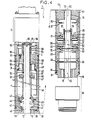
- La figure 2 montre une vue agrandie, partiellement écorchée, d'une partie de la figure 1 consistant en un module d'étanchéité.
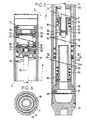
- La figure 3 montre une vue agrandie, partiellement écorchée, d'une autre partie de la figure 1 consistant en un module comportant un réservoir d'expansion et des moyens pour assurer une surpression du fluide dans les moteurs.
- La figure 4 montre le module de la figure 2 en vue plus agrandie et détaillée.
- La figure 5 montre le module de la figure 3 en vue plus agrandie et détaillée.
- La figure 6 est une coupe selon VI-VI de la figure 5.
- Figure 1 shows a motor pump group according to the invention.
- Figure 2 shows an enlarged view, partially broken away, of a part of Figure 1 consisting of a sealing module.
- FIG. 3 shows an enlarged view, partially cut away, of another part of FIG. 1 consisting of a module comprising an expansion tank and means for ensuring an overpressure of the fluid in the engines.
- Figure 4 shows the module of Figure 2 in a more enlarged and detailed view.
- Figure 5 shows the module of Figure 3 in a more enlarged and detailed view.
- Figure 6 is a section on VI-VI of Figure 5.
La figure 1 montre un ensemble moto-pompe constitué par un certain nombre de modules assemblés. Tel que représenté, cet ensemble comporte trois moteurs 1, 2 et 3, un séparateur de gaz 4, deux éléments de pompe 5 et 6, un module d'étanchéité supérieur 7 associé à un module inférieur 8 comportant un réservoir de compensation expansible et des moyens permettant d'assurer une surpression du fluide intérieur aux moteurs : de l'huile, par rapport au milieu extérieur : du pétrole brut, dans le cas de l'application de l'ensemble moto-pompe au pompage de pétrole dans un puits pompé.Figure 1 shows a motor pump assembly consisting of a number of assembled modules. As shown, this assembly comprises three
La partie pompe composée des éléments 5 et 6 est entraînée en rotation par l'arbre moteur de la partie motrice composée des moteurs 1, 2 et 3 et l'aspiration des pompes a lieu au niveau du séparateur de gaz 4 et est représentée par les flèches 9 sur la figure 1.The pump part composed of elements 5 and 6 is rotated by the motor shaft of the drive part composed of
En se reportant maintenant à la figure 4 on va décrire le module supérieur d'étanchéité 7. Ce module est accouplé, à sa partie inférieure, à l'extrémité supérieure du moteur 3 au moyen d'un accouplement 10 non détaillé, et à sa partie supérieure, à l'extrémité inférieure du séparateur de gaz 4 par des moyens d'accouplement non détaillés 11.Referring now to FIG. 4, the
Le module supérieur d'étanchéité 7 est traversé par un arbre 12 provenant des moteurs et allant vers les pompes pour leur entraînement.The
Ce module réalise la séparation entre le fluide interne aux moteurs : de l'huile, et le milieu extérieur en communication avec les pompes : du pétrole, au niveau de la garniture mécanique d'étanchéité dynamique qui comporte un grain fixe 13 et un grain mobile en rotation 14. Il s'agit par exemple d'une garniture mécanique compensée à soufflet métallique soudé permettant une libre dilatation de l'arbre 12.This module performs the separation between the internal fluid of the motors: oil, and the external medium in communication with the pumps: oil, at the level of the dynamic mechanical seal which includes a
L'arbre 12 est guidé en rotation par trois coussinets 15. 16 et 17 respectivement montés dans des paliers 18, 19 et 20 et est arrêté en translation par un dispositif de butée composé de deux butées à patins oscillants montés en opposition de part et d'autre d'un collet de butée 21. Chaque butée comprend par exemple six patins oscillants tels que 22, montés sur leur support en forme de couronne, respectivement 23 et 24. Le collet de butée 21 est lié à l'arbre 12, en rotation par une clavette 25 et en translation par deux demi- coquilles 26 servant de butée latérale, placées dans une gorge de l'arbre 12 et maintenues par un écrou 27 vissé sur un prolongement en forme de manchon 101 du collet de butée 21. Les deux butées sont positionnées dans un tube extérieur 28 par une entretoise supérieure 29 et une entretoise inférieure 30. Les entretoises 29 et 30 sont liées angulairement aux supports de patins 23 et 24 par des pions 31 et 32. L'entretoise inférieure 30 est en appui sur le palier 18 et est immobilisée en rotation par rapport à ce palier au moyen de pions 33. Le palier inférieur 18 est vissé dans le tube extérieur 28 et l'étanchéité est assuré par un joint torique 34.The shaft 12 is guided in rotation by three
Le palier 19 est vissé à l'extrémité supérieure du tube extérieur 28. Ce palier porte deux pions 35 poussés par des ressorts 36 qui, au moment du montage du palier 19, par vissage sur le tube extérieur 28, poussent les pions 35 dans les évidements de passage d'huile 37 de l'entretoise supérieure 29. Une fois que les pions sont rentrés dans ces évidements, le vissage du palier 19 entraîne dans sa rotation, l'entretoise supérieure 29 ainsi que le support 23 et les patins 22 de la butée supérieure.The
Le palier 19 porte une vis 38 obturant un trou de purge 39.The bearing 19 carries a
Le grain fixe 13 de la garniture mécanique d'étanchéité est monté dans un logement du palier 19, il est arrêté en rotation par un pion 40 et en translation par une rondelle 41 fixée sur le palier par trois vis 42.The
Ce module comporte en outre un dispositif de protection de la garniture mécanique d'étanchéité contre les particules solides qui peuvent s'introduire dans la partie supérieure du module en communication avec le milieu extérieur. Ce dispositif comporte d'abord trois pièces fixes soudées les unes aux autres et comprenant une bride de fixation 43 au palier 19 par des vis 44, l'étanchéité étant assuré par un joint torique 45, un tube 46 et un plateau 47. Un deuxième ensemble fixe, solidaire du palier 20, en forme de cloche vient coiffer le plateau 47 et le tube 46, il est composé des pièces 48, 49 et d'un tube 50. L'ensemble est complété par deux déflecteurs rotatifs : un déflecteur inférieur 51, arrêté sur l'arbre par une vis 52 et portant un disque 53, agissant sur les particules solides par effet centrifuge et un déflecteur supérieur 54, arrêté sur l'arbre par une vis 55, l'étanchéité étant assuré par un joint torique 56. Un bouchon 57 est fixé sur le déflecteur supérieur 54 avec l'interposition d'un joint plat 58 par des vis 59. Un trou de purge 63 est percé dans le palier 20 jusque dans la chambre B formée par la pièce 48. Ce trou est bouché par un bouchon de purge 65.This module also includes a device for protecting the mechanical seal against solid particles which can enter the upper part of the module in communication with the outside environment. This device firstly comprises three fixed parts welded to each other and comprising a
Le palier supérieur 20 est vissé sur un tube extérieur 60 lui-même vissé sur le palier intermédiaire 19. Les paliers 18, 19 et 20 sont arrêtés en rotation par rapport aux tubes extérieurs 28 et 60 par des goupilles 61.The upper bearing 20 is screwed onto an
L'arbre 12 est creux et possède au-dessous du grain fixe 13 de la garniture mécanique d'étanchéité des trous de communications 62 pour tous les passages d'huile. Pour ne pas alourdir la figure, les pointillés n'ont pas été représentés sauf sous la butée montrant les passages d'huile dans l'entretoise inférieure 30.The shaft 12 is hollow and has, below the fixed
On va maintenant décrire le module inférieur 8 dont le but est d'assurer une réserve d'huile et de créer une surpression de l'huile dans les moteurs par rapport au milieu extérieur, assurant ainsi un excellent fonctionnement du module d'étanchéité supérieur 7 et en particulier de la garniture mécanique d'étanchéité 13, 14 et permettant une longue durée de vie du groupe moto-pompe.We will now describe the
Les variations volumiques de l'huile dans les moteurs sont compensées par la dilatation ou la contraction d'un réservoir expansible 66. Ce réservoir est constitué par l'assemblage d'un ou plusieurs soufflets métalliques soudés. Chaque soufflet comporte une bride d'assemblage mâle 67 et une bride d'assemblage femelle 68. La bride femelle 68 du soufflet supérieur est fixé par des vis 69 à une pièce support 70 centré dans un tube carcasse extérieur 71, et bloqué par un écrou 72 vissé dans le tube. L'écrou 72 est fendu et comporte une vis de freinage 73. Un joint torique 74 assure l'étanchéité entre le tube 71 et la pièce support 70. De même, un joint torique 75 assure l'étanchéité entre deux soufflets successifs et à l'extrémité supérieure comme on le voit sur la figure, entre le dernier soufflet et la pièce support 70.The variations in volume of the oil in the engines are compensated for by the expansion or contraction of an
La bride mâle 67 du soufflet inférieur est fixée à un fond de réservoir 76 par des vis 77. L'étanchéité entre la bride 67 et le fond 76 est réalisée par un joint torique 75. Un joint plat 78 est placé sous les têtes de vis 77.The
Le fond de réservoir 76 réalise la séparation entre le réservoir 66 et le milieu extérieur : du pétrole brut, lorsque l'ensemble est descendu au fond du puits.The
Une surpression du milieu interne est assurée grâce à la poussée d'un premier ressort 79, extérieur, et d'un second ressort 80, intérieur, appliquée sur une pièce d'appui intermédiaire 81 et transmise au fond du réservoir 76 par l'intermédiaire d'une butée double à billes 82.An overpressure of the internal medium is ensured by the thrust of a
La pièce d'appui intermédiaire 81, avec la butée 82 permettent de ne pas contraindre en torsion le réservoir 66 lors de la compression des ressorts.The
La poussée du ressort intérieur 80 est transmise à la pièce d'appui intermédiaire 81 par un dispositif de décrochage permettant de débander le ressort 80 lorsque son effort de compression atteint une limite prédéterminée. Ce dispositif compend une tige 83 transmettant la poussée du ressort 80 à la pièce d'appui intermédiaire 81. Sur cette tige 83 est montée un tube coulissant 84 qui est solidarisée de la tige 83, en translation, par des billes 85 situées dans des logements du tube et maintenues dans une gorge 86 de la tige 83 par une douille 87 mise en butée contre une rondelle 88 grâce à un ressort 89. La rondelle 88 est arrêtée sur la tige 83 par un circlip 90. La charge du ressort intérieur 80 est transmise au tube coulissant 84 par un manchon 91 en butée contre le tube 84. Un joint racleur 92 est monté à l'extrémité supérieure du tube 84.The thrust of the
Le ressort extérieur 79 est guidé entre le tube carcasse 71 et un tube 93 et s'appuie sur une rondelle 94 centrée sur le tube 93 et arrêtée contre un épaulement 94A du tube 93. Le ressort intérieur 80 est guidé entre le tube 93 et un tube 95 et s'appuie sur un bloc support 96 qui positionne les tubes 93 et 95. Ce bloc support 96 est centré dans le tube carcasse 71 et il est bloqué par un écrou 97 fendu et freiné par une vis 98. L'ensemble du module est fermé par un bloc d'extrémité 99.The
Le tube 93 porte à son extrémité haute un flasque 100 servant de guide pour la tige 83.The
L'extrémité supérieure du tube 95 sert de butée pour la douille 87 lorsque le réservoir 66 s'allonge, comprimant les ressorts 79 et 80. C'est ainsi que s'opère, comme on va l'expliquer lors du fonctionnement, le décrochage du ressort intérieur 80, par coulissement de la douille 87 sur le tube 84, permettant la libération des billes 85 désolidarisant ainsi le tube 84 de la tige 83.The upper end of the
Ce module 8 est situé à l'extrémité inférieure du groupe moto-pompe au-delà de l'extrémité de l'arbre moteur et est vissé au module voisin situé au-dessus, par exemple au moteur 1.This
Le remplissage et la descente dans le puits se font de la manière suivante : les moteurs 1, 2 et 3 et les modules 7 et 8 sont assemblés, la purge 39 du module d'étanchéité 7 est ouverte. L'ensemble des modules est à la pression atmosphérique. Le réservoir expansible 66 est entièrement comprimé sous l'action combinée des ressorts 79 et 80. On remplit les moteurs et le module 8 d'huile qui coule jusqu'au fond 76 du réservoir expansible 66. L'huile est introduite par le module d'étanchéité 7 à la partie supérieure de son arbre creux 12 dans le trou de l'arbre. L'huile monte jusqu'au niveau de la garniture d'étanchéité 13, 14 remplissant les moteurs et toutes les cavités et canaux du module 7 jusqu'à la purge 39. La pression P1 dans le réservoir expansible 66 dépend de la densité d de l'huile et de la hauteur de la colonne d'huile depuis le fond 76 du réservoir 66 jusqu'à la garniture d'étanchéité 13-14. Au niveau de la garniture d'étanchéité, la pression P2 est la pression atmosphérique.Filling and lowering into the well is done as follows: the
La pression P1 sur le fond 76 du réservoir 66 comprime les ressorts 79 et 80 et le réservoir s'étend jusqu'à ce que l'équilibre soit réalisé entre la charge des ressorts et l'effort exercé sur le fond 76 par la pression P1.The pressure P1 on the bottom 76 of the
On ferme alors la purge 39 avec son bouchon 38. On remplit également les cavités repérées A. B, C, par le trou 63. le bouchon 65 étant ôté, on laisse dégazer et on referme. On assemble alors les pompes.The
On descend ensuite cet ensemble dans le puits, l'air qui enveloppait le réservoir expansible 66 est alors remplacé par le fluide extérieur rencontré, la pression extérieure est donc croissante et transmise au milieu interne par le réservoir expansible 66 ainsi que la température qui croît au fur et à mesure de la descente dilatant l'huile contenu dans les moteurs et provoquant l'allongement du réservoir expansible 66.This assembly is then lowered into the well, the air which enveloped the
La pression interne au réservoir 66 est égale à la pression extérieure, due à la colonne de fluide au-dessus du fond 76 du réservoir, plus à la pression due à la poussée des ressorts. La surpression interne par rapport au milieu externe est donc égale à la pression due à la poussée des ressorts. Cette poussée est proportionnelle à l'écrasement des ressorts.The internal pressure in the
Le système de décrochage décrit plus haut permet de limiter à une valeur prédéterminée la surpression. Ce décrochage fonctionne de la façon suivante. Le réservoir 66 se dilatant sous l'effet de l'accroissement de la température, il arrive un moment où la douille 87 vient prendre appui contre l'extrémité haute du tube 95, cette douille coulisse alors sur le tube 84 en comprimant le ressort 89 ce qui permet aux billes 85 de sortir de la gorge 86 désolidarisant le tube 84 de la tige 83 et permettant au ressort intérieur 80 de se débander par coulissement du tube coulissant 84 sur la tige 83. La surpression est alors donnée uniquement par le ressort extérieur 79 calculée pour que la surpression limite admissible ne soit jamais atteinte.The release system described above makes it possible to limit the overpressure to a predetermined value. This dropout works as follows. The
Le dispositif décrit permet ainsi d'absorber toute variation volumique du milieu interne sans risque de pénétration du milieu externe, autorisant un nombre de cycles, arrêts-démarrages, très importants. La surpression assure en outre un excellent fonctionnement de la garniture mécanique 13, 14 du module d'étanchéité 7. Le deuxième ressort interne 80 permet, alors que la pression extérieure est encore l'atmosphère de soutenir la colonne d'huile intérieure, tout en maintenant le réservoir expansible 66 dans une expansion limitée puis de permettre sa dilatation par la suite au cours de la descente ; lors du décrochage, le poids de la colonne d'huile est compensée par la pression extérieure due à la hauteur de fluide au-dessus du fond de réservoir 76 et qui est à peu près égale du côté interne et externe de ce fond à la différence près, due à la différence de densité de l'huile interne par rapport à la densité du fluide interne. La raideur du ressort extérieur 79 est beaucoup plus faible que celle du ressort intérieur 80 et permet, au cours du fonctionnement, d'assurer la surpression désirée dans une limite inférieure à la limite admissible pour les soufflets.The device described thus makes it possible to absorb any variation in volume of the internal medium without risk of penetration of the external medium, allowing a very large number of cycles, stops-starts. The overpressure also ensures excellent operation of the
A titre non limitatif, on donne ci-après un exemple chiffré :
- ressort intérieur 80 : charge maximale 320 kg pour une flèche de 550 mm
- ressort extérieur 79 : charge maximale 300 kg pour une flèche de 1 130 mm
- surface du fond 76 de soufflet: 102 cm2
- densité de l'huile d : 0,873 à 20 °C
- coefficient de dilatation de l'huile : pour un ΔT de 130° : 9,5 %.
- inner spring 80: maximum load 320 kg for a boom of 550 mm
- outer spring 79: maximum load 300 kg for a boom of 1130 mm
- bellows bottom 76 surface: 102 cm 2
- oil density d: 0.873 at 20 ° C
- coefficient of expansion of the oil: for a ΔT of 130 °: 9.5%.
Au départ, avant de remplir les moteurs d'huile, le réservoir est complètement comprimé par les ressorts qui ont une précontrainte de 151 mm pour le ressort extérieur et 110 mm pour le ressort intérieur.At the start, before filling the engines with oil, the tank is completely compressed by the springs which have a preload of 151 mm for the external spring and 110 mm for the internal spring.
On verse alors 71 litres d'huile ce qui provoque une expansion du réservoir 66 de 1 dm3. La colonne d'huile est alors de 28 m, ce qui donne une pression sur le fond de 2,44 bars soit 245 kg.71 liters of oil are then poured which causes the
Au cours de la descente, la température croît, le réservoir se dilate et la pression augmente. Par le système de décrochage, on limite cette pression à 4,5 bars soit 450 kg ; le ressort extérieur supportant alors ces 450 kg moins les 320 kg de charge maximale du ressort intérieur soit 130 kg. Une fois le décrochage, la pression est donc de 1,3 bars, et le réservoir contient 3,5 dm3 d'huile, il s'est allongé de 340 mm. On continu la descente jusqu'au fond.During the descent, the temperature increases, the tank expands and the pressure increases. By the release system, this pressure is limited to 4.5 bars, ie 450 kg; the external spring then supporting these 450 kg minus the 320 kg of maximum load of the internal spring, ie 130 kg. Once the stall, the pressure is therefore 1.3 bars, and the reservoir contains 3.5 dm 3 of oil, it has lengthened by 340 mm. We continue the descent to the bottom.
On met en route les moteurs et pour un fonctionnement à 150° les 71 litres d'huile se dilatent jusqu'à 78 litres et il y a donc 8 litres d'huile dans le soufflet qui peut se dilater jusqu'à 10 litres. Avec 8 litres, et une fuite de 0,5 cm3/h à la garniture d'étanchéité du module 7, on a une réserve d'huile de 1 600 heures.The engines are started and for operation at 150 ° the 71 liters of oil expand up to 78 liters and there is therefore 8 liters of oil in the bellows which can expand up to 10 liters. With 8 liters, and a leak of 0.5 cm 3 / h at the seal of
Claims (2)
Priority Applications (1)
| Application Number | Priority Date | Filing Date | Title |
|---|---|---|---|
| AT83103116T ATE22598T1 (en) | 1982-03-31 | 1983-03-29 | SUBMERSIBLE PUMP COMPOSITION. |
Applications Claiming Priority (2)
| Application Number | Priority Date | Filing Date | Title |
|---|---|---|---|
| FR8205500A FR2524576B1 (en) | 1982-03-31 | 1982-03-31 | MOTOR PUMP UNDERWATER GROUP |
| FR8205500 | 1982-03-31 |
Publications (2)
| Publication Number | Publication Date |
|---|---|
| EP0090411A1 EP0090411A1 (en) | 1983-10-05 |
| EP0090411B1 true EP0090411B1 (en) | 1986-10-01 |
Family
ID=9272585
Family Applications (1)
| Application Number | Title | Priority Date | Filing Date |
|---|---|---|---|
| EP83103116A Expired EP0090411B1 (en) | 1982-03-31 | 1983-03-29 | Submerged motor pump assembly |
Country Status (9)
| Country | Link |
|---|---|
| US (1) | US4477235A (en) |
| EP (1) | EP0090411B1 (en) |
| JP (1) | JPS58182450A (en) |
| AT (1) | ATE22598T1 (en) |
| BR (1) | BR8301650A (en) |
| DE (1) | DE3366525D1 (en) |
| FR (1) | FR2524576B1 (en) |
| NO (1) | NO153744C (en) |
| ZA (1) | ZA832271B (en) |
Families Citing this family (19)
| Publication number | Priority date | Publication date | Assignee | Title |
|---|---|---|---|---|
| US4583923A (en) * | 1984-02-10 | 1986-04-22 | Hughes Tool Company | Bellows latching mechanism for a submersible pump |
| US4768888A (en) * | 1987-04-29 | 1988-09-06 | Mcneil (Ohio) Corporation | Unitary bearing member and motor incorporating the same |
| US5320182A (en) * | 1989-04-28 | 1994-06-14 | Baker Hughes Incorporated | Downhole pump |
| US4940911A (en) * | 1989-06-21 | 1990-07-10 | Oil Dynamics, Inc. | Submersible pump equalizer with multiple expanding chambers |
| US5049046A (en) * | 1990-01-10 | 1991-09-17 | Escue Research And Development Company | Pump control system for a downhole motor-pump assembly and method of using same |
| US5193985A (en) * | 1990-01-10 | 1993-03-16 | Uniflo Oilcorp, Ltd. | Pump control system for a downhole motor-pump assembly and method of using same |
| US5178233A (en) * | 1991-05-10 | 1993-01-12 | Nth, Inc. | Continuous lubrication method and apparatus |
| EP0518371B1 (en) * | 1991-06-14 | 1998-09-09 | Baker Hughes Incorporated | Fluid-actuated wellbore tool system |
| US5765950A (en) * | 1996-11-29 | 1998-06-16 | Goulds Pumps, Incorporated | Thrust bearing assembly |
| US6688860B2 (en) | 2001-06-18 | 2004-02-10 | Schlumberger Technology Corporation | Protector for electrical submersible pumps |
| US7182584B2 (en) * | 2003-09-17 | 2007-02-27 | Schlumberger Technology Corporation | Motor protector |
| US7654315B2 (en) * | 2005-09-30 | 2010-02-02 | Schlumberger Technology Corporation | Apparatus, pumping system incorporating same, and methods of protecting pump components |
| US7708534B2 (en) * | 2007-07-06 | 2010-05-04 | Baker Hughes Incorporated | Pressure equalizer in thrust chamber electrical submersible pump assembly having dual pressure barriers |
| NO333696B1 (en) | 2010-12-17 | 2013-08-26 | Vetco Gray Scandinavia As | System and method for instantaneous hydrostatic operation of hydrodynamic axial bearings in a vertical fluid set-off module |
| CN102297124B (en) * | 2011-07-28 | 2015-08-12 | 天津市百成油田采油设备制造有限公司 | Module type support seat for parallel connection of electric submersible pump protector capsule |
| WO2016089426A1 (en) * | 2014-12-05 | 2016-06-09 | Ge Oil & Gas Esp, Inc. | Mechanical seal protector for esp seal sections |
| WO2017066032A1 (en) * | 2015-10-11 | 2017-04-20 | Schlumberger Technology Corporation | Submersible pumping system thrust bearing gas venting |
| CA3041312A1 (en) | 2016-10-23 | 2018-04-26 | Schlumberger Canada Limited | Gas purging for electric submersible pumping system |
| EP3555482A4 (en) * | 2016-12-16 | 2020-08-12 | Baker Hughes, a GE company, LLC | Electrically powered motor lubricant pressure compensator for submersible pump motor |
Family Cites Families (10)
| Publication number | Priority date | Publication date | Assignee | Title |
|---|---|---|---|---|
| US2011616A (en) * | 1932-11-25 | 1935-08-20 | Automatic Lubrication Ltd | Grease-cup |
| US2236887A (en) * | 1938-03-28 | 1941-04-01 | Reda Pump Company | Submergible deep well pump |
| US2740058A (en) * | 1950-11-30 | 1956-03-27 | Schaefer Edward John | Submergible motor |
| US2682229A (en) * | 1950-12-26 | 1954-06-29 | Us Electrical Motors Inc | Pressure system for submersible structures |
| US2740059A (en) * | 1952-08-13 | 1956-03-27 | F E Myers & Bro Co | Submersible motor |
| US2739252A (en) * | 1953-02-11 | 1956-03-20 | Red Jacket Mfg Co | Immersible electric motor |
| US2962612A (en) * | 1957-03-18 | 1960-11-29 | Tait Mfg Co The | Submersible motor construction |
| US3052804A (en) * | 1959-07-06 | 1962-09-04 | Us Electrical Motors Inc | Fluid filled submersible motor |
| US3255367A (en) * | 1961-06-26 | 1966-06-07 | Franklin Electric Co Inc | Multiple section motor |
| US3369137A (en) * | 1965-08-06 | 1968-02-13 | Smith Corp A O | Expansion bag unit for liquid filled submersible motors |
-
1982
- 1982-03-31 FR FR8205500A patent/FR2524576B1/en not_active Expired
-
1983
- 1983-03-25 NO NO831080A patent/NO153744C/en unknown
- 1983-03-28 JP JP58052286A patent/JPS58182450A/en active Pending
- 1983-03-29 DE DE8383103116T patent/DE3366525D1/en not_active Expired
- 1983-03-29 AT AT83103116T patent/ATE22598T1/en active
- 1983-03-29 EP EP83103116A patent/EP0090411B1/en not_active Expired
- 1983-03-30 US US06/480,616 patent/US4477235A/en not_active Expired - Fee Related
- 1983-03-30 ZA ZA832271A patent/ZA832271B/en unknown
- 1983-03-30 BR BR8301650A patent/BR8301650A/en unknown
Also Published As
| Publication number | Publication date |
|---|---|
| US4477235A (en) | 1984-10-16 |
| JPS58182450A (en) | 1983-10-25 |
| NO153744C (en) | 1986-05-21 |
| EP0090411A1 (en) | 1983-10-05 |
| NO153744B (en) | 1986-02-03 |
| NO831080L (en) | 1983-10-03 |
| BR8301650A (en) | 1983-12-13 |
| FR2524576B1 (en) | 1986-05-09 |
| FR2524576A1 (en) | 1983-10-07 |
| DE3366525D1 (en) | 1986-11-06 |
| ATE22598T1 (en) | 1986-10-15 |
| ZA832271B (en) | 1983-12-28 |
Similar Documents
| Publication | Publication Date | Title |
|---|---|---|
| EP0090411B1 (en) | Submerged motor pump assembly | |
| FR2519688A1 (en) | SEALING SYSTEM FOR DRILLING WELLS IN WHICH CIRCULATES A HOT FLUID | |
| EP0335786B1 (en) | Elastic strut with an integrated hydro-mechanic resonator, in particilar for the suspension of a gear box on a rotorplane, and a suspension device comprising such an application | |
| WO1991000410A1 (en) | Device for guiding a drilling tool into a well and for exerting thereon a hydraulic force | |
| FR2485678A1 (en) | METHOD AND MECHANISM FOR CONTROLLING PRESSURE TO PARTS SECURING A TREE OF A DEVICE AND A FLUID TRANSPORT PUMP USING THE SAME | |
| FR2486996A1 (en) | VALVE DEVICE | |
| FR2479892A1 (en) | DIRECT DRIVE DEVICE FOR DRILL BIT | |
| CA2885071A1 (en) | Rotation lock torque anchor for a well production column, pump and rotation lock system, and pumping facility equipped with such a torque anchor | |
| CA1066586A (en) | Jack stand specially adapted to the toolholder base of a machine, namely a polisher | |
| CA2033367A1 (en) | Device for separating free gas mixed with a liquid at the inlet of a pump in a bored tube-well | |
| EP0063062B1 (en) | Seal for a rotary engine with hydraulic fluid | |
| EP0060181A1 (en) | Prestressed hydropneumatic accumulator with pressure relief | |
| FR2841954A1 (en) | PNEUMATIC SUSPENSION AND VALVE ASSEMBLY FOR A PNEUMATIC SUSPENSION SYSTEM COMBINED WITH A SHOCK ABSORBER | |
| EP0198733A1 (en) | Hydro-elastic device for self-lifting mobile drilling platforms | |
| EP0228929B1 (en) | Device for the antiseismic connection between the lower pump shaft and the sphere of a nuclear reactor | |
| FR2704068A1 (en) | Improved pick-up string | |
| EP1939457A1 (en) | Pump with an elastic device on a bearing | |
| EP1140628A1 (en) | Device for suspending a payload in a launch vehicle | |
| EP1022487A1 (en) | Tensioner comprising hydraulic damping means and method of manufacturing the same | |
| EP0054502B1 (en) | Bearing arrangement for a centrifuge | |
| CA2822038C (en) | Pumping facility for a deep well | |
| EP0242290B1 (en) | Hydraulic ejection device for charges carried by an aircraft | |
| FR2478055A1 (en) | BRAKE ASSEMBLY WITH INTEGRATED LUBRICANT PUMP, PARTICULARLY FOR WELL INSTALLATION WELL | |
| FR3069571B1 (en) | FLUID FILM COMPRESSION SYSTEM AND ROTATING MACHINE COMPRISING SUCH A SYSTEM | |
| EP0130494B1 (en) | Method of protecting a mechanical system with limited movement in an aggressive environment |
Legal Events
| Date | Code | Title | Description |
|---|---|---|---|
| PUAI | Public reference made under article 153(3) epc to a published international application that has entered the european phase |
Free format text: ORIGINAL CODE: 0009012 |
|
| AK | Designated contracting states |
Designated state(s): AT DE FR GB IT SE |
|
| 17P | Request for examination filed |
Effective date: 19840405 |
|
| RAP1 | Party data changed (applicant data changed or rights of an application transferred) |
Owner name: ALSTHOM |
|
| GRAA | (expected) grant |
Free format text: ORIGINAL CODE: 0009210 |
|
| AK | Designated contracting states |
Kind code of ref document: B1 Designated state(s): AT DE FR GB IT SE |
|
| REF | Corresponds to: |
Ref document number: 22598 Country of ref document: AT Date of ref document: 19861015 Kind code of ref document: T |
|
| REF | Corresponds to: |
Ref document number: 3366525 Country of ref document: DE Date of ref document: 19861106 |
|
| ITF | It: translation for a ep patent filed |
Owner name: JACOBACCI & PERANI S.P.A. |
|
| PGFP | Annual fee paid to national office [announced via postgrant information from national office to epo] |
Ref country code: AT Payment date: 19870317 Year of fee payment: 5 |
|
| PLBE | No opposition filed within time limit |
Free format text: ORIGINAL CODE: 0009261 |
|
| STAA | Information on the status of an ep patent application or granted ep patent |
Free format text: STATUS: NO OPPOSITION FILED WITHIN TIME LIMIT |
|
| 26N | No opposition filed | ||
| PG25 | Lapsed in a contracting state [announced via postgrant information from national office to epo] |
Ref country code: GB Effective date: 19890329 Ref country code: AT Effective date: 19890329 |
|
| PG25 | Lapsed in a contracting state [announced via postgrant information from national office to epo] |
Ref country code: SE Effective date: 19890330 |
|
| GBPC | Gb: european patent ceased through non-payment of renewal fee | ||
| PG25 | Lapsed in a contracting state [announced via postgrant information from national office to epo] |
Ref country code: FR Free format text: LAPSE BECAUSE OF NON-PAYMENT OF DUE FEES Effective date: 19891130 |
|
| PG25 | Lapsed in a contracting state [announced via postgrant information from national office to epo] |
Ref country code: DE Effective date: 19891201 |
|
| REG | Reference to a national code |
Ref country code: FR Ref legal event code: ST |
|
| EUG | Se: european patent has lapsed |
Ref document number: 83103116.6 Effective date: 19900124 |