EP0090170B1 - Kapazitiver Schaltungsfilter - Google Patents
Kapazitiver Schaltungsfilter Download PDFInfo
- Publication number
- EP0090170B1 EP0090170B1 EP19830101575 EP83101575A EP0090170B1 EP 0090170 B1 EP0090170 B1 EP 0090170B1 EP 19830101575 EP19830101575 EP 19830101575 EP 83101575 A EP83101575 A EP 83101575A EP 0090170 B1 EP0090170 B1 EP 0090170B1
- Authority
- EP
- European Patent Office
- Prior art keywords
- web
- incision
- coil
- face
- capacitive circuit
- Prior art date
- Legal status (The legal status is an assumption and is not a legal conclusion. Google has not performed a legal analysis and makes no representation as to the accuracy of the status listed.)
- Expired
Links
- 238000000576 coating method Methods 0.000 claims description 37
- 239000002184 metal Substances 0.000 claims description 28
- 239000011248 coating agent Substances 0.000 claims description 17
- 238000000926 separation method Methods 0.000 claims description 10
- 239000003989 dielectric material Substances 0.000 claims description 4
- 239000003990 capacitor Substances 0.000 description 7
- 238000010586 diagram Methods 0.000 description 5
- 238000009413 insulation Methods 0.000 description 4
- 238000003801 milling Methods 0.000 description 4
- 238000012986 modification Methods 0.000 description 4
- 230000004048 modification Effects 0.000 description 4
- 238000004519 manufacturing process Methods 0.000 description 2
- 230000015572 biosynthetic process Effects 0.000 description 1
- 238000007796 conventional method Methods 0.000 description 1
- 238000005538 encapsulation Methods 0.000 description 1
- 230000001788 irregular Effects 0.000 description 1
- 238000000034 method Methods 0.000 description 1
- 239000011347 resin Substances 0.000 description 1
- 229920005989 resin Polymers 0.000 description 1
- 238000004804 winding Methods 0.000 description 1
Images


Classifications
-
- H—ELECTRICITY
- H01—ELECTRIC ELEMENTS
- H01G—CAPACITORS; CAPACITORS, RECTIFIERS, DETECTORS, SWITCHING DEVICES, LIGHT-SENSITIVE OR TEMPERATURE-SENSITIVE DEVICES OF THE ELECTROLYTIC TYPE
- H01G4/00—Fixed capacitors; Processes of their manufacture
- H01G4/38—Multiple capacitors, i.e. structural combinations of fixed capacitors
- H01G4/385—Single unit multiple capacitors, e.g. dual capacitor in one coil
Definitions
- This invention relates to a capacitive circuit filter, particularly of the T configuration type, adapted for example to be employed for eliminating disturbances occurring during operation of electrical apparatus with the danger of repercussion into the electric power supply network.
- a filter of this type comprises at least two Y-type capacities connected between the respective phases of the electric power supply and ground, and at least two X-type capacities connected between the phases of the electric power supply.
- An arrangement of this type requires specialized and highly complicated machinery for forming the discontinuous metallic layer, particularly if it is intended to obtain a greater number of capacitors for establishing a more sophisticated circuit.
- capacitive circuit filters comprising a combination of capacitors formed by providing the coatings with suitable incisions so as to obtain a capacitive circuit of the desired configuration.
- These filters are normally formed by winding a metallized dielectric web onto a disk or a drum having a large diameter for forming a parent capacitor which is then subdivided into the required capacities, with the incisions being formed contemporaneously or subsequently for obtaining individual capacitive circuit filters.
- this object is attained by a capacitive circuit filter formed by coiling at least one first web of a dielectric material provided with at least one continuous metallic coating leaving the lateral borders of the web uncovered, and at least one second web of a dielectric material provided with at least two continuous metallic coatings extending up to the lateral borders of the web and separated from one another by a zone which is free of metallic coating.
- a filter of this type is principally characterized in that there is provided at least one first incision extending from one end face of the coil at least into the separation zone between the metallic coatings of the second web.
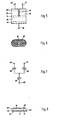
- the filter according to the invention is formed by coiling a first dielectric web 10 provided with a continuous metal coating 11 on one of its surfaces, and a second dielectric web 12 provided on one of its surfaces with two continuous metal coatings 13, 14 separated from one another.
- the metallic coating 11 extends over the surface of web 10 so as to leave two lateral border zones 15, 16 thereof uncovered, whereas the metallic coatings 13, 14 on web 12 extend up to the lateral borders thereof, being separated from one another by a non-coated separation zone 17.
- the body of the capacitor thus obtained is provided with at least two incisions 18, 19 extending parallel to the axis of the filter coil.
- the incision 18 is formed, preferably by milling, between two terminals 20 and 21 provided for connection to the phases of the electric supply circuit, and extends downwards from the respective end face of the coil into the separation zone 17 between the coatings 13 and 14 of web
- the incision 19 is formed between terminals 20, 21 on the one hand, and a terminal 22 on the other, provided for connection to ground, and extends to the level of the opposite non-coated border zone 16 of web 10.
- the two end faces of the coil are provided with a metal coating 23 (Fig. 3), and the terminals 20, 21 and 22 are attached to one of said end faces so as to be connected to one and the same metal coating 13 or 14 of web 12.
- the filter comprises two X-type capacities 24, 25 connected in series between the two terminals 20 and 21 for connection to the electric supply source, and three Y-type capacities 26, 27 and 28 connected in series with one another and the respective one of capacities 24 or 25 between terminals 20, 21 and ground terminal 22.
- a simplified practical embodiment of the filter according to the invention may be obtained in the form of the modification shown in Figs. 5 and 6, comprising a single coil formed of the metal-coated webs 10 and 12 of Fig. 1.
- incision 18 In the body of the coil thus obtained, only a single incision 18 is formed between the terminals 20 and 21.
- the incision 18 extends parallel to the axis of the coil from one end face thereof into the separation zone 17 between the metal coatings 13 and 14 of web 12.
- Fig. 7 shows the circuit diagram of this modification, comprising two X-type capacities connected in series between terminals 20 and 21 for connection to the electric power supply.
- a Y-type capacity 26 is connected between terminals 20, 21 and ground terminal 22 in series with the respective capacity 24 or 25.
- the values of the individual capacities may be varied independently of the characteristics of the single incision 18 by varying the widths of the metallic coatings 11 and 13, 14, respectively, on webs 10 and 12.
- the coil of the filter may of course be formed of dielectric webs having different numbers of metal coatings.
- web 10 may be provided with a second continuous metal coating 29 adjacent to but separate from coating 11.
- web 12 may be provided with a third metal coating 30 adjacent to but separate from coating 14, extending up to the respective edge of web 12 for connection to ground terminal 22.
- the incision 18 extends into the coil from the end face thereof adajcent metal coating 13 of web 12 and into the separation zone 17, so as not to exert any influence on the Y-type capacities 26, 27 and 28.
- the metal coatings of the webs are cleanly severed at the location of the respective incisions, which are preferably formed by milling, as already explained. This results in the creation of numerous short circuit points between the metal coatings at these locations.
- the autoregeneration current is substantially increased due to the presence of the numerous short circuit points, which may lead to the dielectric webs being burnt, resulting in undesirable changes of the.parameters of the entire filter.
- the capacitive filter is obtained for instance by coiling the metal-coated webs 10 and 12 of Fig. 1 and by practicing the at least one incision 18 in a direction substantially oblique with respect to the axis of the coil.
- the incision is preferably formed by the traditional milling technique, with the oblique orientation of the plane of the milling tool with respect to the axis of the coil resulting in the metal coatings of the webs being severed in an irregular manner adjacent the location of the incision.
- the filter according to the invention is completed by providing both end faces of the coil with a short-circuiting metal coating and attaching the terminals 20 and 21 to the end face formed with the incision 18, while the ground terminal 22 is attached to the opposite end face.
- the coil of this filter may of course be formed by employing dielectric webs having a different number and/or arrangement of metal coatings.
- the filter according to the invention may be formed with numerous different circuit arrangements, possibly by combining the various embodiments described, without leaving the scope of the invention as defined in the appended claims.
Landscapes
- Engineering & Computer Science (AREA)
- Power Engineering (AREA)
- Manufacturing & Machinery (AREA)
- Microelectronics & Electronic Packaging (AREA)
- Coils Or Transformers For Communication (AREA)
- Filters And Equalizers (AREA)
Claims (5)
Priority Applications (1)
| Application Number | Priority Date | Filing Date | Title |
|---|---|---|---|
| AT83101575T ATE23930T1 (de) | 1982-03-30 | 1983-02-18 | Kapazitiver schaltungsfilter. |
Applications Claiming Priority (4)
| Application Number | Priority Date | Filing Date | Title |
|---|---|---|---|
| IT4571582 | 1982-03-30 | ||
| IT45715/82A IT1159758B (it) | 1982-03-30 | 1982-03-30 | Filtro a rete capacitiva |
| IT45722/82A IT1159762B (it) | 1982-07-07 | 1982-07-07 | Filtro a rete capacitiva |
| IT4572282 | 1982-07-07 |
Publications (3)
| Publication Number | Publication Date |
|---|---|
| EP0090170A2 EP0090170A2 (de) | 1983-10-05 |
| EP0090170A3 EP0090170A3 (en) | 1984-09-12 |
| EP0090170B1 true EP0090170B1 (de) | 1986-11-26 |
Family
ID=26329170
Family Applications (1)
| Application Number | Title | Priority Date | Filing Date |
|---|---|---|---|
| EP19830101575 Expired EP0090170B1 (de) | 1982-03-30 | 1983-02-18 | Kapazitiver Schaltungsfilter |
Country Status (2)
| Country | Link |
|---|---|
| EP (1) | EP0090170B1 (de) |
| DE (1) | DE3367988D1 (de) |
Cited By (1)
| Publication number | Priority date | Publication date | Assignee | Title |
|---|---|---|---|---|
| DE19510624C1 (de) * | 1995-03-23 | 1996-08-29 | Eichhoff Werke | Wickelkondensator mit X-Y-Mehrfachkapazität |
Families Citing this family (3)
| Publication number | Priority date | Publication date | Assignee | Title |
|---|---|---|---|---|
| IT1187291B (it) * | 1985-09-06 | 1987-12-23 | Zanussi Elettromecc | Filtro a rete capacitiva ad avvolgimento unico |
| SE452524B (sv) * | 1985-09-13 | 1987-11-30 | Ericsson Telefon Ab L M | Kondensatorenhet med minst tre kondensatorer |
| DE102019103832A1 (de) * | 2019-02-15 | 2020-08-20 | Webasto SE | Vorrichtung zur Unterdrückung von EMV-Gleichtaktstörungen in Kfz- Hochvoltanwendungen |
Family Cites Families (3)
| Publication number | Priority date | Publication date | Assignee | Title |
|---|---|---|---|---|
| DE1764861C3 (de) * | 1968-08-20 | 1974-03-21 | Siemens Ag, 1000 Berlin U. 8000 Muenchen | Kapazitives Netzwerk |
| BE754515R (fr) * | 1969-08-06 | 1971-02-08 | Siemens Ag | Reseau |
| DE2830961C3 (de) * | 1978-07-14 | 1981-07-09 | Standard Elektrik Lorenz Ag, 7000 Stuttgart | Funk-Entstörkondensator |
-
1983
- 1983-02-18 EP EP19830101575 patent/EP0090170B1/de not_active Expired
- 1983-02-18 DE DE8383101575T patent/DE3367988D1/de not_active Expired
Cited By (1)
| Publication number | Priority date | Publication date | Assignee | Title |
|---|---|---|---|---|
| DE19510624C1 (de) * | 1995-03-23 | 1996-08-29 | Eichhoff Werke | Wickelkondensator mit X-Y-Mehrfachkapazität |
Also Published As
| Publication number | Publication date |
|---|---|
| DE3367988D1 (en) | 1987-01-15 |
| EP0090170A2 (de) | 1983-10-05 |
| EP0090170A3 (en) | 1984-09-12 |
Similar Documents
| Publication | Publication Date | Title |
|---|---|---|
| US4352145A (en) | Multiple element cylindrical metallized film capacitors and method of making the same | |
| US4028595A (en) | Multi-voltage capacitor section | |
| US4263638A (en) | Dial wound capacitor and method of making same | |
| US3921041A (en) | Dual capacitor | |
| US5313360A (en) | Dual Capacitor | |
| US3617834A (en) | Monolithic capacitor components and process for producing same | |
| EP0090170B1 (de) | Kapazitiver Schaltungsfilter | |
| US4622620A (en) | Electric capacitor with polyethylene terephthalate as a dielectric for use as a solderable chip component | |
| US5644468A (en) | Metallized wound-dielectricalization condenser X-Y multiple capacitances | |
| FI77338C (fi) | Framstaellningsfoerfarande av en sjaelvregenererande kondensator. | |
| US2070435A (en) | Electric condenser | |
| US2683792A (en) | Means for making metalized electrical condensers | |
| US4470097A (en) | Dual film metallized capacitor | |
| US2503418A (en) | Electrical resistor and method of making the same | |
| US4356608A (en) | Method for the manufacture of layer capacitors | |
| EP0109090B1 (de) | Mehrfachkondensatorwicklung mittels eines metallisierten Bandmaterials | |
| DE3463314D1 (en) | Electrical capacitor consisting of an integral pile of stacked metallized dielectric sheets, and process for making it | |
| US4639832A (en) | Consolidated winding electrical capacitor and method for the manufacture thereof | |
| US4127891A (en) | Pleated metallized film capacitor with sprayed edge terminations | |
| US5043612A (en) | Epoxy coated motor with shading band having tapered edges | |
| US4128857A (en) | Pleated metallized film capacitor wound about its center | |
| EP0133290B1 (de) | Verfahren zur Herstellung von einstückigen kapazitiven Schaltungen | |
| US2736677A (en) | Metallized insulators | |
| US5012565A (en) | Method for the manufacture of layered capacitors having a thickness of inactive layers | |
| EP0215361B1 (de) | Mit einer einzigen Wicklung hergestelltes kapazitives Netzwerkfilter |
Legal Events
| Date | Code | Title | Description |
|---|---|---|---|
| PUAI | Public reference made under article 153(3) epc to a published international application that has entered the european phase |
Free format text: ORIGINAL CODE: 0009012 |
|
| AK | Designated contracting states |
Designated state(s): AT BE CH DE FR GB IT LI NL SE |
|
| PUAL | Search report despatched |
Free format text: ORIGINAL CODE: 0009013 |
|
| RAP1 | Party data changed (applicant data changed or rights of an application transferred) |
Owner name: ZANUSSI ELETTROMECCANICA S.P.A. |
|
| AK | Designated contracting states |
Designated state(s): AT BE CH DE FR GB IT LI NL SE |
|
| 17P | Request for examination filed |
Effective date: 19841122 |
|
| 17Q | First examination report despatched |
Effective date: 19860213 |
|
| GRAA | (expected) grant |
Free format text: ORIGINAL CODE: 0009210 |
|
| AK | Designated contracting states |
Kind code of ref document: B1 Designated state(s): AT BE CH DE FR GB IT LI NL SE |
|
| REF | Corresponds to: |
Ref document number: 23930 Country of ref document: AT Date of ref document: 19861215 Kind code of ref document: T |
|
| REF | Corresponds to: |
Ref document number: 3367988 Country of ref document: DE Date of ref document: 19870115 |
|
| ITF | It: translation for a ep patent filed | ||
| ET | Fr: translation filed | ||
| PLBE | No opposition filed within time limit |
Free format text: ORIGINAL CODE: 0009261 |
|
| STAA | Information on the status of an ep patent application or granted ep patent |
Free format text: STATUS: NO OPPOSITION FILED WITHIN TIME LIMIT |
|
| 26N | No opposition filed | ||
| ITPR | It: changes in ownership of a european patent |
Owner name: CESSIONE;PROCOND ELETTRONICA S.P.A. |
|
| ITTA | It: last paid annual fee | ||
| REG | Reference to a national code |
Ref country code: GB Ref legal event code: 732 |
|
| REG | Reference to a national code |
Ref country code: CH Ref legal event code: PUE Owner name: PROCOND ELETTRONICA S.P.A. |
|
| REG | Reference to a national code |
Ref country code: FR Ref legal event code: TP |
|
| NLS | Nl: assignments of ep-patents |
Owner name: PROCOND ELETTRONICA S.P.A. TE PORDENONE, ITALIE. |
|
| EAL | Se: european patent in force in sweden |
Ref document number: 83101575.5 |
|
| REG | Reference to a national code |
Ref country code: GB Ref legal event code: IF02 |
|
| PGFP | Annual fee paid to national office [announced via postgrant information from national office to epo] |
Ref country code: AT Payment date: 20020110 Year of fee payment: 20 |
|
| PGFP | Annual fee paid to national office [announced via postgrant information from national office to epo] |
Ref country code: FR Payment date: 20020114 Year of fee payment: 20 |
|
| PGFP | Annual fee paid to national office [announced via postgrant information from national office to epo] |
Ref country code: GB Payment date: 20020117 Year of fee payment: 20 |
|
| PGFP | Annual fee paid to national office [announced via postgrant information from national office to epo] |
Ref country code: CH Payment date: 20020118 Year of fee payment: 20 |
|
| PGFP | Annual fee paid to national office [announced via postgrant information from national office to epo] |
Ref country code: NL Payment date: 20020121 Year of fee payment: 20 Ref country code: DE Payment date: 20020121 Year of fee payment: 20 |
|
| PGFP | Annual fee paid to national office [announced via postgrant information from national office to epo] |
Ref country code: SE Payment date: 20020122 Year of fee payment: 20 |
|
| PGFP | Annual fee paid to national office [announced via postgrant information from national office to epo] |
Ref country code: BE Payment date: 20020213 Year of fee payment: 20 |
|
| PG25 | Lapsed in a contracting state [announced via postgrant information from national office to epo] |
Ref country code: LI Free format text: LAPSE BECAUSE OF EXPIRATION OF PROTECTION Effective date: 20030217 Ref country code: GB Free format text: LAPSE BECAUSE OF EXPIRATION OF PROTECTION Effective date: 20030217 Ref country code: CH Free format text: LAPSE BECAUSE OF EXPIRATION OF PROTECTION Effective date: 20030217 |
|
| PG25 | Lapsed in a contracting state [announced via postgrant information from national office to epo] |
Ref country code: NL Free format text: LAPSE BECAUSE OF EXPIRATION OF PROTECTION Effective date: 20030218 Ref country code: AT Free format text: LAPSE BECAUSE OF EXPIRATION OF PROTECTION Effective date: 20030218 |
|
| BE20 | Be: patent expired |
Owner name: *PROCOND ELETTRONICA S.P.A. Effective date: 20030218 |
|
| REG | Reference to a national code |
Ref country code: GB Ref legal event code: PE20 Effective date: 20030217 |
|
| REG | Reference to a national code |
Ref country code: CH Ref legal event code: PL |
|
| EUG | Se: european patent has lapsed | ||
| NLV7 | Nl: ceased due to reaching the maximum lifetime of a patent |
Effective date: 20030218 |