EP0090141A2 - Fused carbonate fuel cell - Google Patents
Fused carbonate fuel cell Download PDFInfo
- Publication number
- EP0090141A2 EP0090141A2 EP83100824A EP83100824A EP0090141A2 EP 0090141 A2 EP0090141 A2 EP 0090141A2 EP 83100824 A EP83100824 A EP 83100824A EP 83100824 A EP83100824 A EP 83100824A EP 0090141 A2 EP0090141 A2 EP 0090141A2
- Authority
- EP
- European Patent Office
- Prior art keywords
- electrolyte
- fuel cell
- binder
- fused carbonate
- fuel
- Prior art date
- Legal status (The legal status is an assumption and is not a legal conclusion. Google has not performed a legal analysis and makes no representation as to the accuracy of the status listed.)
- Withdrawn
Links
Images
Classifications
-
- H—ELECTRICITY
- H01—ELECTRIC ELEMENTS
- H01M—PROCESSES OR MEANS, e.g. BATTERIES, FOR THE DIRECT CONVERSION OF CHEMICAL ENERGY INTO ELECTRICAL ENERGY
- H01M8/00—Fuel cells; Manufacture thereof
- H01M8/14—Fuel cells with fused electrolytes
- H01M8/141—Fuel cells with fused electrolytes the anode and the cathode being gas-permeable electrodes or electrode layers
- H01M8/142—Fuel cells with fused electrolytes the anode and the cathode being gas-permeable electrodes or electrode layers with matrix-supported or semi-solid matrix-reinforced electrolyte
-
- H—ELECTRICITY
- H01—ELECTRIC ELEMENTS
- H01M—PROCESSES OR MEANS, e.g. BATTERIES, FOR THE DIRECT CONVERSION OF CHEMICAL ENERGY INTO ELECTRICAL ENERGY
- H01M8/00—Fuel cells; Manufacture thereof
- H01M8/02—Details
- H01M8/0289—Means for holding the electrolyte
- H01M8/0295—Matrices for immobilising electrolyte melts
-
- H—ELECTRICITY
- H01—ELECTRIC ELEMENTS
- H01M—PROCESSES OR MEANS, e.g. BATTERIES, FOR THE DIRECT CONVERSION OF CHEMICAL ENERGY INTO ELECTRICAL ENERGY
- H01M8/00—Fuel cells; Manufacture thereof
- H01M8/14—Fuel cells with fused electrolytes
- H01M2008/147—Fuel cells with molten carbonates
-
- H—ELECTRICITY
- H01—ELECTRIC ELEMENTS
- H01M—PROCESSES OR MEANS, e.g. BATTERIES, FOR THE DIRECT CONVERSION OF CHEMICAL ENERGY INTO ELECTRICAL ENERGY
- H01M2300/00—Electrolytes
- H01M2300/0017—Non-aqueous electrolytes
- H01M2300/0048—Molten electrolytes used at high temperature
- H01M2300/0051—Carbonates
-
- Y—GENERAL TAGGING OF NEW TECHNOLOGICAL DEVELOPMENTS; GENERAL TAGGING OF CROSS-SECTIONAL TECHNOLOGIES SPANNING OVER SEVERAL SECTIONS OF THE IPC; TECHNICAL SUBJECTS COVERED BY FORMER USPC CROSS-REFERENCE ART COLLECTIONS [XRACs] AND DIGESTS
- Y02—TECHNOLOGIES OR APPLICATIONS FOR MITIGATION OR ADAPTATION AGAINST CLIMATE CHANGE
- Y02E—REDUCTION OF GREENHOUSE GAS [GHG] EMISSIONS, RELATED TO ENERGY GENERATION, TRANSMISSION OR DISTRIBUTION
- Y02E60/00—Enabling technologies; Technologies with a potential or indirect contribution to GHG emissions mitigation
- Y02E60/30—Hydrogen technology
- Y02E60/50—Fuel cells
Definitions
- the present invention relates to a fused carbonate type of fuel cell. More particularly, the present invention relates to a fuel cell comprising an electrolytic body retaining an electrolyte therein.
- electrolytic body There are two types of electrolytic body, one type is an electrolytic body comprising an electrolyte retained in a porous ceramic sintered body (hereinafter called a “matrix type of electrolytic body” ) and the other type is a molded body of a mixture of non-electroconductive fine particles and an electrolyte (hereinafter called a "paste type of electrolytic body”).
- matrix type of electrolytic body a porous ceramic sintered body
- the conventional electrolytic bodies are not satisfactory in the following points.
- a fuel cell of the fused carbonate type comprising an electrolytic body retaining an electrolyte therein, which is arranged between an anode and a cathode, in which electricity is electrochemically generated by feeding fuel gas to a fuel chamber arranged on the anode side and feeding an oxidant to an oxidant chamber arranged on the cathode side, said fuel cell being characterized in that the electrolytic body comprises the electrolyte, an electrolyte-retaining member for retaining the electrolyte and an inorganic binder.
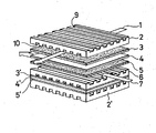
- the figure shows a perspective view of an important part of a fused carbonate fuel cell assembly to which the present invention is applied.
- the present invention has been completed as the result of research made with a view to solve the following two problems simultaneously. Namely, with a matrix type of electrolytic body, deformation such as warping readily occurs in the molded body during high-temperature sintering, and with a paste type of electrolytic body, the mechanical strength is low.
- a fused carbonate fuel cell shown in Figure is constituted by a separater 2, 2' made of an electrically conductive, heat resistant material, such as stainless steel (SUS 316), a cathode plate 3, 3' made of a catalytic material such as sintered nickel compact, an electrolytic body 4, 4' made of a porous ceramic tile which is impregnated with an electrolytic composition such as K 2 CO 3 , Li 2 CO 3 , and or Na 2 C0 3 an anode plate 5, 5' made of the catalytic material, and a separater 6 made of an electrically conductive, heat resistant material (SUS 316).
- SUS 316 electrically conductive, heat resistant material
- the separator 2, 2' has a plurality of grooves 9 or 10 on each end face thereof; one group of grooves 9 on one face constitutes a gas passage for fuel gas such as hydrogen gas 7, and the other group of grooves 10 on the other face constitutes a gas passage for oxidant gas such as air 1 .
- the gas passage 10 is used for carrying carbon dioxide gas which is produced by fuel reaction into of the fuel cell together with air .
- the assemblies are generally stacked as shown in Figure by a compressive force to assure an electrical connection between the separators and electrodes .
- a metal salt of a polyacid is used as the inorganic binder.
- a polyacid is an oxyacid which forms a poly-nuclear complex salt having at least two nuclei by the condensation of acid groups .
- Polyacids are often observed with respect to elements of groups III and VI of the Periodic Table, especially boron, silicon, phosphorus, sulfur, vanadium, niobium, tantalum, chromium, molybdenum and tungsten.
- isopolyacids comprising one central ion, such as tripolyphosphate (H 5 P 3 O 10 ), and heteropolyacids comprising at least two central ions, such as silicontungstic acid (H 3 HSiW 12 O 40 ).
- the inventors have found that when a metal salt of such an inorganic polymeric substance is used as the binder, the binding properties of the electrolyte-retaining member are increased and an electrolytic body having an increased electrolyte capacity can be obtained.
- a salt of a polyphosphoric acid is particularily excellent as the binder.
- a phosphate for example, an alkali metal dihydrogenphosphate
- an alkali metal metaphosphate which is a white vitreous substance, as given by the following formula:
- this polyacid salt acts as a strong binder and binds the electrolyte-retaining member tightly.
- alkali metal salts but also alkaline earth metal salts and other salts such as salts of titanium, zirconium or tin can be used as the metal salt.
- the electrolyte is an alkali metal carbonate, in view of its affinity to alkali metal carbonates, an alkali metal salt of polyphosphoric acid is most preferred.
- salts of other polyacids for example borates or sodium silicates
- a similar effect can be attained, and a salt of a heteropolyacid such as a phosphomolybdate shows a certain effect.
- the electrolyte-retaining member is mixed with the precursor of the polyacid salt at a predetermined ratio, the mixture is formed into a molded body and the molded body is heat-treated, whereby the precursor is converted to the polyacid salt and simultaneously the polyacid salt binds the electrolyte-retaining member.
- An alkali metal carbonate used as the electrolyte is fused and the resultant heated molded body is impregnated with the fused alkali metal carbonate.
- the electrolyte-retaining member, the polyacid salt or its precursor, and the electrolyte are mixed together at a predetermined ratio, the mixture is formed into a molded body and the molded body is sintered at the lowest temperature necessary for obtaining the binding effect, whereby a paste type of electrolytic body is obtained.
- lithium aluminate having an average particle size of 0.5 microns was mixed with 34 g of top grade reagent lithium dihydrogenphosphate (LiH 2 PO 4 ), water was added to the mixture and the resulting mixture was kneaded sufficiently.
- the mixture was dried at 140°C for 2 hours, pulverized to 100 mesh by a pulverizer and graded.
- the pulverized mixture was formed into a molded body having a length of 200 mm, a width of 200 mm and a thickness of 1 .5 mm by using a cold press.
- the molded body was heated to 700°C with the temperature increasing at 100 C/h while being degassed, and the molded body was maintained at this temperature for about 2 hours .
- the temperature was then lowered to 550°C .
- a mixed electrolyte of lithium carbonate and potassium carbonate (at a molar ratio of 62/38) was fused and the molded body comprising the electrolyte-retaining member and the binder (about 30% by weight) was impregnated with the fused electrolyte.
- the impregnated molded body was then cooled to obtain the electrolytic body.
- Sintered bodies of porous nickel and of lithium containing nickel oxide were used as the anode and cathode respectively.
- a single cell was made by using these electrodes and the electrolytic body obtained by the above method, putting the latter between both said electrodes, then the cell performance was measured.
- a mixed gas comprising 50% hydrogen and 50% nitrogen was supplied to a fuel chamber on the anode side, and a mixed gas comprising 15% oxygen, 30% carbon dioxide, and 55% nitrogen was supplied to an oxidant chamber on the cathode side, and the cell was operated at 650 C.
- the cell was discharged at a current density of 100 mA/cm2 and the cell voltage was measured, it was found that the initial value was 0.80 V and the value after the lapse of 100 hours was 0.81 V, and the capacity was not reduced even by 100 hours of operation. No substantial leakage of gas from a wet seal was observed during the operation. Furthermore, when shut-down (650°C ⁇ 300°C) was repeated (three times), no gas-cross phenomenon was observed.
- magnesia powder having a mean particle size of 1 .0 ⁇ m was mixed with 10g. of sodium silicate; then the mixture was admixed with water, and the aqueous mixture was thoroughly kneeded .
- the composition was dried at 140°C for 2 hours.
- the resulting mixture was ground with a ball milling machine .to produce powder which passes a 100 mesh sieve (Taylor).
- the resulting powder was cold-pressed to form a plate of 1 .5 mm thick and 100 mm wide X 100 mm long.
- the green plate was heated by elevating a temperature at a rate of 100°C/h to 900°C and calcined at 900 0 C for 3 hours, then the temperature was lowered to 550°C.
- the resulting plate (electrolyte retaining member) which consists of about 90% by weight of magnesia and about 10% by weight of the binder (sodium silicate) was impregnated with a mixed electrolyte composition consisting of 62 mole % of lithium carbonate and 38 mole % of pottasium carbonate by fusing the composition.
- Cell voltages at a discharge of 1 00mA/cm 2 were 0.79V (initial) and 0 .8V (after 100 hours).
- H 5 P 3 O 10 was used to prepare an electrolytic body .
- This body also exhibited substantially the same characteristics as the body of Example 1 .
Landscapes
- Life Sciences & Earth Sciences (AREA)
- Engineering & Computer Science (AREA)
- Manufacturing & Machinery (AREA)
- Sustainable Development (AREA)
- Sustainable Energy (AREA)
- Chemical & Material Sciences (AREA)
- Chemical Kinetics & Catalysis (AREA)
- Electrochemistry (AREA)
- General Chemical & Material Sciences (AREA)
- Fuel Cell (AREA)
Abstract
Description
- The present invention relates to a fused carbonate type of fuel cell. More particularly, the present invention relates to a fuel cell comprising an electrolytic body retaining an electrolyte therein.
- There are two types of electrolytic body, one type is an electrolytic body comprising an electrolyte retained in a porous ceramic sintered body (hereinafter called a "matrix type of electrolytic body" ) and the other type is a molded body of a mixture of non-electroconductive fine particles and an electrolyte (hereinafter called a "paste type of electrolytic body").
- The conventional electrolytic bodies are not satisfactory in the following points.
- (1) Warping or formation of cracks can occur in the electrolytic body during the preparation process.
- (2) Cracks can be formed during the operation of the cell.
- (3) Thermal deformation can occur during the operation of the cell.
- (4) The electrolyte capacity is low.
- It is a primary object of the present invention to provide a fuel cell comprising an electrolytic body in which the above defects of conventional fuel cells are eliminated, with good molding properties and a high mechanical strength, an excellent electrolyte capacity, and in which a high cell capacity is stably exerted.
- In accordance with the present invention, a fuel cell of the fused carbonate type is provided comprising an electrolytic body retaining an electrolyte therein, which is arranged between an anode and a cathode, in which electricity is electrochemically generated by feeding fuel gas to a fuel chamber arranged on the anode side and feeding an oxidant to an oxidant chamber arranged on the cathode side, said fuel cell being characterized in that the electrolytic body comprises the electrolyte, an electrolyte-retaining member for retaining the electrolyte and an inorganic binder.
- The figure shows a perspective view of an important part of a fused carbonate fuel cell assembly to which the present invention is applied.
- In the following the invention is described in detail by means of preferred embodiments.
- The present invention has been completed as the result of research made with a view to solve the following two problems simultaneously. Namely, with a matrix type of electrolytic body, deformation such as warping readily occurs in the molded body during high-temperature sintering, and with a paste type of electrolytic body, the mechanical strength is low.
- A fused carbonate fuel cell shown in Figure is constituted by a separater 2, 2' made of an electrically conductive, heat resistant material, such as stainless steel (SUS 316), a
cathode plate 3, 3' made of a catalytic material such as sintered nickel compact, an electrolytic body 4, 4' made of a porous ceramic tile which is impregnated with an electrolytic composition such as K2CO3, Li2CO3, and or Na2C03 an anode plate 5, 5' made of the catalytic material, and a separater 6 made of an electrically conductive, heat resistant material (SUS 316). - The separator 2, 2' has a plurality of
grooves 9 or 10 on each end face thereof; one group of grooves 9 on one face constitutes a gas passage for fuel gas such as hydrogen gas 7, and the other group ofgrooves 10 on the other face constitutes a gas passage for oxidant gas such as air 1 . Thegas passage 10 is used for carrying carbon dioxide gas which is produced by fuel reaction into of the fuel cell together with air . - The assemblies are generally stacked as shown in Figure by a compressive force to assure an electrical connection between the separators and electrodes .
- According to a preferred embodiment, a metal salt of a polyacid is used as the inorganic binder.
- A polyacid is an oxyacid which forms a poly-nuclear complex salt having at least two nuclei by the condensation of acid groups . Polyacids are often observed with respect to elements of groups III and VI of the Periodic Table, especially boron, silicon, phosphorus, sulfur, vanadium, niobium, tantalum, chromium, molybdenum and tungsten. Among these polyacids, there are isopolyacids comprising one central ion, such as tripolyphosphate (H5P3O10), and heteropolyacids comprising at least two central ions, such as silicontungstic acid (H3 HSiW12O40).
- The inventors have found that when a metal salt of such an inorganic polymeric substance is used as the binder, the binding properties of the electrolyte-retaining member are increased and an electrolytic body having an increased electrolyte capacity can be obtained.
- Of such inorganic polymeric substances, a salt of a polyphosphoric acid is particularily excellent as the binder.
- As is well-known, when orthophosphoric acid is heated, dehydration occurs to form a viscous syrup, and when the dehydration is further advanced, the syrup becomes a white vitreous substance, that is, metaphosphoric acid. This conversion is shown by the following formula :

- Similarly, a phosphate, for example, an alkali metal dihydrogenphosphate, is finally converted by dehydration to an alkali metal metaphosphate which is a white vitreous substance, as given by the following formula:

- It has been found that when this reaction is carried·out in the presence of an electrolyte-retaining member, this polyacid salt acts as a strong binder and binds the electrolyte-retaining member tightly.
- Not only alkali metal salts but also alkaline earth metal salts and other salts such as salts of titanium, zirconium or tin can be used as the metal salt. However, in the fused carbonate type of fuel cell, since the electrolyte is an alkali metal carbonate, in view of its affinity to alkali metal carbonates, an alkali metal salt of polyphosphoric acid is most preferred.
- When salts of other polyacids, for example borates or sodium silicates, are used as the binder, a similar effect can be attained, and a salt of a heteropolyacid such as a phosphomolybdate shows a certain effect.
- According to one method for obtaining the electrolytic body of the present invention, the electrolyte-retaining member is mixed with the precursor of the polyacid salt at a predetermined ratio, the mixture is formed into a molded body and the molded body is heat-treated, whereby the precursor is converted to the polyacid salt and simultaneously the polyacid salt binds the electrolyte-retaining member. An alkali metal carbonate used as the electrolyte is fused and the resultant heated molded body is impregnated with the fused alkali metal carbonate. There is also a method in which, before the step of impregnation with the electrolyte, the temperature is raised to sinter the molded body comprising the electrolyte-retaining member and the binder, and the sintered body is then impregnated with the electrolyte. In this method, it is necessary that the operation should be controlled so that warping does not occur during the sintering step.
- In another method, the electrolyte-retaining member, the polyacid salt or its precursor, and the electrolyte are mixed together at a predetermined ratio, the mixture is formed into a molded body and the molded body is sintered at the lowest temperature necessary for obtaining the binding effect, whereby a paste type of electrolytic body is obtained.
- The present invention will now be described in detail with reference to the following example.
- 66 g of lithium aluminate having an average particle size of 0.5 microns was mixed with 34 g of top grade reagent lithium dihydrogenphosphate (LiH2PO4), water was added to the mixture and the resulting mixture was kneaded sufficiently. The mixture was dried at 140°C for 2 hours, pulverized to 100 mesh by a pulverizer and graded. The pulverized mixture was formed into a molded body having a length of 200 mm, a width of 200 mm and a thickness of 1 .5 mm by using a cold press. The molded body was heated to 700°C with the temperature increasing at 100 C/h while being degassed, and the molded body was maintained at this temperature for about 2 hours . The temperature was then lowered to 550°C . A mixed electrolyte of lithium carbonate and potassium carbonate (at a molar ratio of 62/38) was fused and the molded body comprising the electrolyte-retaining member and the binder (about 30% by weight) was impregnated with the fused electrolyte. The impregnated molded body was then cooled to obtain the electrolytic body.
- Sintered bodies of porous nickel and of lithium containing nickel oxide were used as the anode and cathode respectively. A single cell was made by using these electrodes and the electrolytic body obtained by the above method, putting the latter between both said electrodes, then the cell performance was measured.
- A mixed gas comprising 50% hydrogen and 50% nitrogen was supplied to a fuel chamber on the anode side, and a mixed gas comprising 15% oxygen, 30% carbon dioxide, and 55% nitrogen was supplied to an oxidant chamber on the cathode side, and the cell was operated at 650 C. When the cell was discharged at a current density of 100 mA/cm2 and the cell voltage was measured, it was found that the initial value was 0.80 V and the value after the lapse of 100 hours was 0.81 V, and the capacity was not reduced even by 100 hours of operation. No substantial leakage of gas from a wet seal was observed during the operation. Furthermore, when shut-down (650°C → 300°C) was repeated (three times), no gas-cross phenomenon was observed.
- 90g. of magnesia powder having a mean particle size of 1 .0µm was mixed with 10g. of sodium silicate; then the mixture was admixed with water, and the aqueous mixture was thoroughly kneeded . The composition was dried at 140°C for 2 hours. The resulting mixture was ground with a ball milling machine .to produce powder which passes a 100 mesh sieve (Taylor).
- The resulting powder was cold-pressed to form a plate of 1 .5 mm thick and 100 mm wide X 100 mm long. The green plate was heated by elevating a temperature at a rate of 100°C/h to 900°C and calcined at 9000C for 3 hours, then the temperature was lowered to 550°C.
- The resulting plate (electrolyte retaining member) which consists of about 90% by weight of magnesia and about 10% by weight of the binder (sodium silicate) was impregnated with a mixed electrolyte composition consisting of 62 mole % of lithium carbonate and 38 mole % of pottasium carbonate by fusing the composition.
- Using the resulting electrolytic body, cell characteristics were measured in the same manner as in Example 1 .
- Cell voltages at a discharge of 1 00mA/cm2 were 0.79V (initial) and 0 .8V (after 100 hours).
- After the 3 repetitions of shut-downs of the fuel cell no gas cross over was observed.
- In place of LiH2PO4 used in Example 1, H5P3O10 was used to prepare an electrolytic body .
- This body also exhibited substantially the same characteristics as the body of Example 1 .
Claims (4)
characterized in that the electrolytic body comprises an electrolyte, an electrolyte-retaining member for retaining the electrolyte and an inorganic binder.
Applications Claiming Priority (2)
| Application Number | Priority Date | Filing Date | Title |
|---|---|---|---|
| JP57011516A JPS58129782A (en) | 1982-01-29 | 1982-01-29 | Fused carbonate type fuel cell |
| JP11516/82 | 1982-01-29 |
Publications (2)
| Publication Number | Publication Date |
|---|---|
| EP0090141A2 true EP0090141A2 (en) | 1983-10-05 |
| EP0090141A3 EP0090141A3 (en) | 1984-09-05 |
Family
ID=11780160
Family Applications (1)
| Application Number | Title | Priority Date | Filing Date |
|---|---|---|---|
| EP83100824A Withdrawn EP0090141A3 (en) | 1982-01-29 | 1983-01-28 | Fused carbonate fuel cell |
Country Status (4)
| Country | Link |
|---|---|
| US (1) | US4476199A (en) |
| EP (1) | EP0090141A3 (en) |
| JP (1) | JPS58129782A (en) |
| CA (1) | CA1191888A (en) |
Families Citing this family (6)
| Publication number | Priority date | Publication date | Assignee | Title |
|---|---|---|---|---|
| EP0124262B1 (en) * | 1983-03-31 | 1987-11-11 | Kabushiki Kaisha Toshiba | Molten carbonate fuel cell |
| JPS6132361A (en) * | 1984-07-23 | 1986-02-15 | Hitachi Ltd | Fuel cell |
| US5292599A (en) * | 1991-09-27 | 1994-03-08 | Ngk Insulators, Ltd. | Cell units for solid oxide fuel cells and power generators using such cell units |
| US5468573A (en) * | 1994-06-23 | 1995-11-21 | International Fuel Cells Corporation | Electrolyte paste for molten carbonate fuel cells |
| US6066408A (en) * | 1997-08-07 | 2000-05-23 | Plug Power Inc. | Fuel cell cooler-humidifier plate |
| EP1941575A1 (en) * | 2005-09-30 | 2008-07-09 | Battelle Memorial Institute | Fuel cell components including immobilized heteropolyacids |
Family Cites Families (7)
| Publication number | Priority date | Publication date | Assignee | Title |
|---|---|---|---|---|
| US3658597A (en) * | 1969-03-13 | 1972-04-25 | Texas Instruments Inc | Method of making fuel cell electrolyte matrix |
| US4111968A (en) * | 1976-06-04 | 1978-09-05 | The Upjohn Company | Process |
| US4086396A (en) * | 1977-02-23 | 1978-04-25 | The United States Of America As Represented By The United States Department Of Energy | Electrochemical cell with powdered electrically insulative material as a separator |
| US4057678A (en) * | 1977-03-16 | 1977-11-08 | The United States Of America As Represented By The United States Energy Research And Development Administration | Molten salt battery having inorganic paper separator |
| JPS5485350A (en) * | 1977-12-19 | 1979-07-06 | Sanyo Electric Co | Fuel cell |
| DE2847464A1 (en) * | 1978-11-02 | 1980-05-14 | Varta Batterie | SEPARATOR FOR ELECTROCHEMICAL HIGH TEMPERATURE CELLS |
| US4317865A (en) * | 1980-09-24 | 1982-03-02 | United Technologies Corporation | Ceria matrix material for molten carbonate fuel cell |
-
1982
- 1982-01-29 JP JP57011516A patent/JPS58129782A/en active Granted
-
1983
- 1983-01-26 US US06/461,255 patent/US4476199A/en not_active Expired - Lifetime
- 1983-01-28 EP EP83100824A patent/EP0090141A3/en not_active Withdrawn
- 1983-01-28 CA CA000420526A patent/CA1191888A/en not_active Expired
Also Published As
| Publication number | Publication date |
|---|---|
| US4476199A (en) | 1984-10-09 |
| EP0090141A3 (en) | 1984-09-05 |
| JPH0449751B2 (en) | 1992-08-12 |
| CA1191888A (en) | 1985-08-13 |
| JPS58129782A (en) | 1983-08-02 |
Similar Documents
| Publication | Publication Date | Title |
|---|---|---|
| US3404035A (en) | Secondary battery employing molten alkali metal reactant | |
| US4895774A (en) | Molten carbonate fuel cell | |
| KR20170129238A (en) | Doped conductive oxide and improved electrochemical energy storage device polar plate based on same | |
| CA1187135A (en) | Fuel cell | |
| CA1278031C (en) | Molten carbonate cathodes and method of fabricating | |
| KR101410605B1 (en) | HIGH LITHIUM ELECTROLYTE FOR MOLECULAR CARBONATE FUEL CELL AND METHOD FOR MANUFACTURING THE SAME | |
| US4476199A (en) | Fused carbonate fuel cell | |
| KR102063688B1 (en) | Fuel cell matrix composition and method of manufacturing same | |
| US4581303A (en) | Process for making structure for a MCFC | |
| CA1174271A (en) | Fuel cell provided with electrolyte plate made of electrical insulating long fibers | |
| EP1883986B1 (en) | Electrolyte matrix for molten carbonate fuel cells with improved pore size and method of manufacturing same | |
| KR100224546B1 (en) | Cathode for molten carbonate fuel cell to which alkali earth metal oxide is added and a process for preparing thereof | |
| US5510210A (en) | Solid electrolyte for sodium-sulfur secondary cell and process for preparing the same | |
| US4939111A (en) | Cathode for molten carbonate fuel cell | |
| KR100368561B1 (en) | Method for Manufacturing Electrolyte Plate of Molten Carbonate Fuel Cells | |
| JPH0412591B2 (en) | ||
| KR100779741B1 (en) | Reinforcing Matrix for Molten Carbonate Fuel Cell with Sintering Aid | |
| KR20250076560A (en) | Method for manufacturing materials or components for solid-state batteries | |
| JPH01120774A (en) | Manufacture of electrolyte tile of molten carbonate fuel cell | |
| JP3219220B2 (en) | Air electrode precursor green sheet and molten carbonate fuel cell using the same | |
| JPH0626130B2 (en) | Method for manufacturing electrolyte plate for molten carbonate fuel cell | |
| KR100331081B1 (en) | A method for making anode of molten carbonate fuel cell | |
| JPH0350387B2 (en) | ||
| Kaun et al. | Cathode for molten carbonate fuel cell | |
| Arons et al. | Porous electrode preparation method |
Legal Events
| Date | Code | Title | Description |
|---|---|---|---|
| PUAI | Public reference made under article 153(3) epc to a published international application that has entered the european phase |
Free format text: ORIGINAL CODE: 0009012 |
|
| AK | Designated contracting states |
Designated state(s): DE FR GB IT |
|
| PUAL | Search report despatched |
Free format text: ORIGINAL CODE: 0009013 |
|
| AK | Designated contracting states |
Designated state(s): DE FR GB IT |
|
| 17P | Request for examination filed |
Effective date: 19840928 |
|
| STAA | Information on the status of an ep patent application or granted ep patent |
Free format text: STATUS: THE APPLICATION IS DEEMED TO BE WITHDRAWN |
|
| 18D | Application deemed to be withdrawn |
Effective date: 19851214 |
|
| RIN1 | Information on inventor provided before grant (corrected) |
Inventor name: OKABE, SHIGERU Inventor name: TAKEUCHI, MASATO Inventor name: OKADA, HIDEO Inventor name: TOBITA, HIROSHI Inventor name: TONAMI, MUNEHIKO |