EP0090070A2 - Fixation device for motor bicycles - Google Patents
Fixation device for motor bicycles Download PDFInfo
- Publication number
- EP0090070A2 EP0090070A2 EP82105250A EP82105250A EP0090070A2 EP 0090070 A2 EP0090070 A2 EP 0090070A2 EP 82105250 A EP82105250 A EP 82105250A EP 82105250 A EP82105250 A EP 82105250A EP 0090070 A2 EP0090070 A2 EP 0090070A2
- Authority
- EP
- European Patent Office
- Prior art keywords
- frame parts
- pannier
- holders
- luggage rack
- mounting device
- Prior art date
- Legal status (The legal status is an assumption and is not a legal conclusion. Google has not performed a legal analysis and makes no representation as to the accuracy of the status listed.)
- Granted
Links
Images


Classifications
-
- B—PERFORMING OPERATIONS; TRANSPORTING
- B62—LAND VEHICLES FOR TRAVELLING OTHERWISE THAN ON RAILS
- B62J—CYCLE SADDLES OR SEATS; AUXILIARY DEVICES OR ACCESSORIES SPECIALLY ADAPTED TO CYCLES AND NOT OTHERWISE PROVIDED FOR, e.g. ARTICLE CARRIERS OR CYCLE PROTECTORS
- B62J7/00—Luggage carriers
Definitions
- the invention relates to a mounting device for motorcycles, for attaching panniers and luggage, as well as indicators, cat eyes and the like. according to the preamble of claim 1.
- Such a mounting device made of die casting is described and shown in German utility model 77 07 615.
- This known mounting device has a right and left side pannier holder, two frame parts attached to it, a luggage rack connecting the frame parts and attached to them, and an adjustable cross strut attached to the pannier holders.
- the luggage rack attached between the frame parts is firmly connected to the frame parts. If this known mounting device is attached to a motorcycle, in most cases a seat which is provided on the motorcycles and is designed to be foldable can practically not be folded up at all in most cases, or at most it can only be lifted up a little.
- the seat since the tool and in many cases the battery are housed under the seat in general, in order to have unhindered access to these parts, the seat must be folded up.
- the luggage rack attached between the frame parts of the mounting device must be unscrewed, which is extremely annoying, tedious and time-consuming.
- the luggage rack must be screwed back to the frame parts of the mounting device, which is just as annoying and time-consuming as removing the luggage rack.
- the object of the invention is therefore to provide a stable, unbreakable mounting device with luggage rack for motorcycles of different widths, in which the luggage rack does not have to be removed to fold up a motorcycle seat. According to the invention, this is achieved in a mounting device for motorcycles according to the preamble of claim 1 by the features in the characterizing part of claim 1. Advantageous developments of the invention are specified in the subclaims.
- the mounting device according to the invention is made of a resistant, unbreakable plastic, such as polyamide 6, which is reinforced with 30 to 33% glass fibers.
- the frame parts attached to the pannier holder as well as the pannier holders themselves are designed in the embodiment of a holding device according to the invention in such a way that when one looks in the usual direction of travel of a motorcycle, which one the mounting device according to the invention is attached, the frame parts of which are guided to the rear and can be folded back together with the luggage rack connecting them.
- guides are formed at the rear upper end in the pannier holders, in which loosened fastening screws can slide; these guides are designed in such a way that the frame parts and the luggage rack connected to them can first be moved backwards against the direction of travel and can then be folded down by about 90 ° to the rear.
- an elastically deformable securing part is attached to each pannier holder, which after folding up the luggage rack and after advancing the frame parts behind one at the front end of each lower extension part of the frame part formed projection and between the bottom of the lower connecting part of each frame part and the top of the upper connecting part of each pannier holder is to be inserted. Due to the resilient design of the securing part, it is securely accommodated and held at the point described above. If motorcycle cases are attached to and in the pannier holders, the safety parts are prevented from falling out by the attached and fastened case.
- pannier holder according to the invention can also be used with as many motorbikes of different widths
- slot-shaped recesses are provided on the underside of the luggage rack, into which locking nuts can be inserted from the outside, so that the width of the holding device is thereby in one Range between 27cm and 34cm is changeable.
- the width of the mounting device can be varied again between 34cm to 41cm by inserting, moving and appropriately securing extension plates in the slots (s) provided on the long sides of the luggage rack for the locking nuts; ie
- the width of the holder device according to the invention can be changed to 41cm total of cm in a range of 2. 7
- FIGS. 1 to 5 identical or corresponding parts are designated with the same reference symbols.
- express reference is made to the drawings because of its great clarity and clarity.
- the holding device designated in its entirety by 1, has two lateral pannier holders 2, two frame parts attached to it and a luggage rack 4 connecting the frame parts and attached to them.
- a cross strut (not shown in detail) that can be adjusted to the width of the respective motorcycle type is fastened by means of screws in bores 27 in the rear connecting part 24 of each pannier holder 2.
- mounting tongue are attached, which are inserted into the lock attached to a motorcycle case in order to hold and secure suitcases suspended in the pannier holder 2.
- the pannier holders 2 have approximately the shape of a parallelogram both in the perspective view of FIG. 1 and in the top view of FIG. 2, the upper and lower connecting parts 21 and 22 being approximately horizontal and front and rear connecting parts 23 and 24 being light run obliquely, approximately at an angle of the order of 10 ° to the vertical. Furthermore, 25 holes 26 are provided at the front rounded corners for attachment to parts leading to a motorcycle frame.
- the approximately horizontal connecting parts 21 and 22 and the rear, slightly oblique connecting part 24 of the pannier holders 2 are formed approximately in a double T-shape, while the front, slightly oblique connecting part 23 is T-shaped in cross section.
- the connecting part of the pannier holder 2 At the upper, rear end of the upper, as seen in the direction of travel Guides 6 and 7 and a receiving area 221 are formed in the connecting part of the pannier holder 2, which is shown in more detail in FIG.
- the frame parts 3 are, as can be seen from the perspective illustration in FIG. 1 and the top view in FIG. 2, essentially in the form of a parallelogram, the upper and lower connecting parts 33 and 34 being approximately horizontal and front and rear connecting parts 31 or 32 run at an angle to the vertical in the order of about 40 °.
- the lower connecting part 34 of the frame parts 3 has at its rear end viewed in the direction of travel an extension 35 with square cutouts 37 (see FIG. 4) for receiving fastening screws 38 and with a bore 36 for fastening a turn signal.
- a longitudinally slotted and conically tapering extension 342 is formed, which is slightly lower than the lower connecting part 34.
- the luggage rack 4 as can be seen from the perspective illustration in FIG. 1, is approximately rectangular in plan view and has a plurality of openings 41 and on its longitudinal sides a plurality, preferably four slot-shaped recesses 42, into which square locknuts can be inserted, into which screws guided from below through holes 39 in the upper connecting part 33 of the frame part. Since only three bores or guides 39 are formed in the upper connecting part 33, but preferably four slot-shaped recesses 42 in the luggage rack 4, the position of the luggage rack 4 with respect to the frame parts 3 can be fastened in two different positions by the distance between two slot-shaped recesses 42 be so that the luggage rack to the dimensions can be adapted to a certain extent against the rear of a motorcycle.
- a plastic filament 51 and a not shown in detail there g t ell t there E i nkl ip s t e i l is mounted in a recess formed at the upper connecting portion 22 of bore 52nd
- this securing part 5 is to be inserted between the lower connecting part 34 of each frame part 3 and the upper connecting part 22 of each pannier holder, viewed in the direction of travel, before the attachment with the bore 52. In this way, an unintentional displacement of the frame parts and thus a folding down of the luggage rack 4 is reliably prevented.
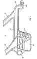
- FIG. 3 shows the rear, viewed in the direction of travel, of a pannier holder 2 which, at the connection point between the upper connection part 22 and the rear, slightly inclined connection part 24, has a projection with the two guides 6 and 7 projecting backwards as viewed in the direction of travel .
- the upper guide 6 has a part 61 which extends approximately horizontally in the extension of the upper connecting part 22 and which merges into a quarter circle 62 oriented downwards.
- the lower guide 7 is arranged at a predetermined distance from the horizontal part 61 of the upper guide and has only one horizontal part corresponding to this horizontal part 61.
- a pivot point 71 is indicated in FIG.
- the length of the lower guide 7 is dimensioned such that the conically tapering extension 342 at the front end 341 of the lower connecting part 34 of the frame parts 3 is sufficient for folding over the luggage rack 4 can be moved far (as seen in the direction of travel) to the rear.
- the receiving area 221 for the slotted and tapered extension 341 at the front end of the connecting part 34 of each frame part 3 is shown in plan view and in Figure 3a in a sectional view along the line A-A in Figure 3 in detail.
- the receiving area 221 has, as can be seen in particular from FIG. Seen in the direction of travel, an attachment with a bore 52 is shown behind the receiving area 221, into which a clip-in part is clipped, which is connected to the securing part by the plastic thread 51 (see FIG. 1).
- FIG. 4 shows an enlarged representation of the lower connecting part 34 of a frame part 3.
- an extension 342 which is slit in the longitudinal direction and tapered towards the front (as seen in the direction of travel) is formed, which is offset with respect to the lower connecting part 34 and is arranged somewhat lower than the connecting part 34.
- the extension 35 is formed, which has an extension at its rear end with a bore 36, where a turn signal is fastened by means of a screw.
- two square holes 37 are formed, through which the fastening screws 38 are inserted, by means of which the frame part 3 is fastened to the respective pannier holder 2.
- a folded-up frame part 3 with the luggage rack 4 attached to it is pulled out in plan view shown. Furthermore, the folded-down frame part 3 with the luggage rack 4 is shown in broken lines in FIG. 2, the pivoting range of approximately 90 ° being indicated by a dashed quarter circle.
- the slotted, tapered extension 342 of each frame part 3 sits in the correspondingly designed recess 323 of the upper connecting part 22 of the respective pannier holder 2
- the conical design of the extension 342 and the recess 232 ensure good guiding and securing.
- the frame parts 3 can then be folded back together with the luggage rack 4 about the pivot point 71, in which case the shoulder 342 disengages from the insertion part 222 and the upper fastening screw 38 slides in the quarter circle 62 of the upper guide 6.
- the above-described processes and movements are carried out in the reverse order, so that after the insertion of the extension 342 into the insertion part 222 and after insertion of the extension 342 into the recess 223, only the four fastening screws 38 are now tightened firmly and that Security part 5 is to be introduced in the manner described.
- FIG. 5 schematically shows a part of a luggage rack 4 and the upper end of a frame part 3 with its connecting parts 31 to 33.
- three extension plates 43 are shown, each of which has two threaded holes 44. So that in a particularly wide rear section of a motorcycle, the mounting device 1 can be adapted accordingly, instead of the locking nuts used otherwise for fastening the frame parts, the extension plates 43 are inserted into the corresponding slots 42 and according to the required width of the mounting device by means of screws, not shown, in the luggage rack 4 secured.
- the frame parts 3 are then at the outer end of the connecting plate 43 fastened by inserting screws, not shown, through the guides 39 in the upper connecting part 33 and screwing them into the outer, threaded bores 44.
- the width of the mounting device 1 can additionally be varied in a range from 34 cm to 41 cm, as mentioned at the beginning.
Abstract
Description
Die Erfindung betrifft eine Halterungseinrichtung für Motorräder, zum Anbringen von Packtaschen und Gepäckstükken sowie von Blinkern, Katzenaugen u.ä. nach dem Oberbegriff des Anspruchs 1.The invention relates to a mounting device for motorcycles, for attaching panniers and luggage, as well as indicators, cat eyes and the like. according to the preamble of
Eine derartige,aus Druckguß hergestellte Halterungseinrichtung ist in dem deutschen Gebrauchsmuster 77 07 615 beschrieben und dargestellt. Diese bekannte Halterungseinrichtung weist je eine rechte und linke seitliche Packtaschenhalterung, zwei daran befestigte Rahmenteile, eine die Rahmenteile verbindende und an diesen angebrachte Gepäckbrücke sowie eine verstellbare, an den Packtaschenhalterungen angebrachte Querverstrebung auf. Bei dieser bekannten Halterungseinrichtung ist die zwischen den Rahmenteilen angebrachte Gepäckbrücke fest mit den Rahmenteilen verbunden. Wenn diese bekannte Halterungseinrichtung an einem Motorrad angebracht ist, kann bei den meisten Ausführungen eine an den Motorrädern vorgesehene, hochklappbar ausgebildete Sitzbank in vielen Fällen praktisch überhaupt nicht hochgeklappt werden oder sie kann allenfalls nur etwas angehoben werden. Da jedoch unter der Sitzbank im allgemeinen das Werkzeug und in vielen Fällen auch die Batterie untergebracht ist, muß, um ungehinderten Zugang zu diesen Teilen zu haben, die Sitzbank hochgeklappt werden können. Bei der bekannten Halterungseinrichtung muß dann jedoch, um die Sitzbank vollständig aufklappen zu können, die zwischen den Rahmenteilen der Halterungseinrichtung angebrachte Gepäckbrücke abgeschraubt werden, was ausgesprochen lästig, mühsam und zeitaufwendig ist. Sobald dann das Werkzeug und/oder die Batterie und andere Teile, wie beispielsweise Handschuhe u.ä. wieder unter der Sitzbank verstaut und diese wieder heruntergeklappt ist, muß die Gepäckbrücke wieder mit den Rahmenteilen der Halterungseinrichtung verschraubt werden, was genauso lästig und zeitaufwendig wie das Abnehmen der Gepäckbrücke ist.Such a mounting device made of die casting is described and shown in German utility model 77 07 615. This known mounting device has a right and left side pannier holder, two frame parts attached to it, a luggage rack connecting the frame parts and attached to them, and an adjustable cross strut attached to the pannier holders. In this known mounting device, the luggage rack attached between the frame parts is firmly connected to the frame parts. If this known mounting device is attached to a motorcycle, in most cases a seat which is provided on the motorcycles and is designed to be foldable can practically not be folded up at all in most cases, or at most it can only be lifted up a little. However, since the tool and in many cases the battery are housed under the seat in general, in order to have unhindered access to these parts, the seat must be folded up. In the known mounting device, however, in order to be able to open the seat completely, the luggage rack attached between the frame parts of the mounting device must be unscrewed, which is extremely annoying, tedious and time-consuming. As soon as the tool and / or the Battery and other parts, such as gloves and the like. Stowed again under the seat and this is folded down again, the luggage rack must be screwed back to the frame parts of the mounting device, which is just as annoying and time-consuming as removing the luggage rack.
Aufgabe der Erfindung ist es daher, eine stabile, bruchsichere Halterungseinrichtung mit Gepäckbrücke für Motorräder unterschiedlicher Breite zu schaffen, bei welcher zum Hochklappen einer Motorrad-Sitzbank die Gepäckbrücke nicht abgenommen zu werden braucht. Gemäß der Erfindung ist dies bei einer Halterungseinrichtung für Motorräder nach dem Oberbegriff des Anspruchs 1 durch die Merkmale im kennzeichnenden Teil des Anspruchs 1 erreicht. Vorteilhafte Weiterbildungen der Erfindung sind in den Unteransprüchen angegeben.The object of the invention is therefore to provide a stable, unbreakable mounting device with luggage rack for motorcycles of different widths, in which the luggage rack does not have to be removed to fold up a motorcycle seat. According to the invention, this is achieved in a mounting device for motorcycles according to the preamble of
Zur Schaffung einer stabilen, hochfesten Halterungseinrichtung ist die erfindungsgemäße Halterungseinrichtung aus einem widerstandsfähigen, bruchfesten Kunststoff, wie beispielsweise Polyamid 6 hergestellt, das mit 30 bis 33% Glasfasern verstärkt ist.To create a stable, high-strength mounting device, the mounting device according to the invention is made of a resistant, unbreakable plastic, such as
Um zum Hochklappen einer Motorrad-Sitzbank die Gepäckbrücke der Halterungseinrichtung nicht abnehmen zu müssen, sind bei der erfindungsgemäßen Ausführung einer Halterungseinrichtung die an deren Packtaschenhalterung angebrachten Rahmenteile sowie die Packtaschenhalterungen selbst so ausgebildet, daß, wenn in der üblichen Fahrtrichtung eines Motorrades gesehen wird, an welchem die erfindungsgemäße Halterungseinrichtung angebracht ist, deren Rahmenteile geführt nach hinten verschiebbar sind und zusammen mit der sie verbindenden Gepäckbrücke nach hinten umklappbar sind. Hierzu sind (in Fahrtrichtung gesehen) am hinteren oberen Ende Führungen in den Packtaschenhalterungen ausgebildet, in welchen gelockerte Befestigungsschrauben gleiten können; diese Führungen sind so ausgebildet, daß die Rahmenteile und die damit verbundene Gepäckbrücke zuerst entgegen der Fahrtrichtung nach hinten verschiebbar sind und dann um etwa 90° nach hinten heruntergeklappt werden können.In order not to have to remove the luggage rack of the holding device to fold up a motorcycle seat, the frame parts attached to the pannier holder as well as the pannier holders themselves are designed in the embodiment of a holding device according to the invention in such a way that when one looks in the usual direction of travel of a motorcycle, which one the mounting device according to the invention is attached, the frame parts of which are guided to the rear and can be folded back together with the luggage rack connecting them. For this purpose (seen in the direction of travel) guides are formed at the rear upper end in the pannier holders, in which loosened fastening screws can slide; these guides are designed in such a way that the frame parts and the luggage rack connected to them can first be moved backwards against the direction of travel and can then be folded down by about 90 ° to the rear.
Wenn somit der Motorradfahrer die Motorrad-Sitzbank aus irgendeinem Grund hochklappen will, braucht er bei der erfindungsgemäßen Halterungseinrichtung nur die Befestigungsschrauben zu lockern, dann die beiden Rahmenteile nach hinten zu verschieben und sie zusammen mit der sie verbindenden Brücke nach hinten unten umzuklappen, worauf er dann schon einen ungehinderten freien Zugang zu der Sitzbank und nach deren Hochklappen einen ungehinderten Zugang zu beispielsweise unter der Sitzbank untergebrachtem Werkzeug, unter Umständen zu der unter der Sitzbank untergebrachten Batterie oder auch zu unter der Sitzbank angeordneten Teilen, wie Handschuhen u.ä., hat. Wenn dann der Motorradfahrer die dem Raum unter der Sitzbank entnommenen Teile nicht mehr benötitgt und wieder unter der Sitzbank verstaut hat, braucht er die Sitzbank nur wieder herunterzuklappen, die Rahmenteile mit der Gepäckbrücke hochzuklappen und nach vorne zu schieben und dann die Befestigungsschrauben wieder anzuziehen. Im Vergleich zu der herkömmlichen Halterungseinrichtung ist somit das Hochklappen der Sitzbank und damit ein freier ungehinderter Zugang zu den unter der Sitzbank untergebrachten Teile sehr viel leichter möglich und bei weitem nicht mehr so mühsam und zeitaufwendig wie bei der herkömmlichen Halterungseinrichtung, bei welcher die Gepäckbrücke vollkommen abgenommen werden mußte, während im Unterschied hierzu bei der erfindungsgemäßen Einrichtung nur vier Befestigungsschrauben gelockert zu werden brauchen, um die Rahmenteile mit der Gepäckbrücke nach hinten verschieben und umklappen zu können.Thus, when the motorcyclists will fold up the motorcycle seat for any reason, he needs with the inventive H aging device only the fixing screws to loosen, then move the two frame parts backwards and they to fold together with the associated bridge back down, whereupon he then already has unhindered free access to the seat and, after folding it up, unhindered access to, for example, tools located under the seat, possibly to the battery housed under the seat or also to parts arranged under the seat, such as gloves, etc. . Then when the motorcyclist no longer needs the parts removed from the room under the seat and stowed them under the seat again, he only needs to fold the seat down again, fold up the frame parts with the luggage rack and slide them forward and then tighten the fastening screws again. Compared to the conventional mounting device, the folding up of the seat and thus free unhindered access to the parts housed under the seat is much easier and far less tedious and time-consuming than with the conventional mounting device, which completely removed the luggage rack had to be, whereas in contrast to this, only four fastening screws need to be loosened in the device according to the invention in order to be able to move the frame parts with the luggage rack to the rear and fold them over.
Wenn ein Motorradfahrer nach dem Hochklappen der Rahmenteile und der Gepäckbrücke vergessen hat, die Befestigungsschrauben wieder anzuziehen, oder wenn er sie nicht fest genug angezogen hat, könnte es während einer anschließenden Fahrt zu einem unbeabsichtigten Herunterklappen der Rahmenteile und der Gepäckbrücke sowie der auf dieser angebrachten Teile kommen. Um ein solches unbeabsichtigtes und nicht ungefährliches Herunterklappen der Rahmenteile und der Gepäckbrücke zu verhindern, ist gemäß einer bevorzugten Ausführungsform der Erfindung an jeder Packtaschenhalterung ein elastisch verformbares Sicherungsteil angebracht, welches nach dem Hochklappen der Gepäckbrücke und nach dem Vorschieben der Rahmenteile hinter einem am vorderen Ende jedes unteren Verlängerungsteils des Rahmenteils ausgebildeten Ansatzes und zwischen der Unterseite des unteren Verbindungsteils jedes Rahmenteils und der Oberseite des oberen Verbindungsteils jeder Packtaschenhalterung einzuschieben ist. Durch die elastisch federnde Ausbildung des Sicherungsteils ist es sicher an der vorstehend beschriebenen Stelle untergebracht und gehaltert. Falls an und in den Packtaschenhalterungen Motorradkoffer angebracht sind, ist ein Herausfallen der Sicherungsteile zusätzlich durch den eingehängten und befestigten Koffer verhindert.If a motorcyclist after folding up the frame parts and the luggage rack has forgotten to tighten the fastening screws again, or if he has not tightened them sufficiently, the frame parts and the luggage rack and the parts attached to them could accidentally fold down during a subsequent journey. In order to prevent such an unintentional and not harmless folding down of the frame parts and the luggage rack, according to a preferred embodiment of the invention, an elastically deformable securing part is attached to each pannier holder, which after folding up the luggage rack and after advancing the frame parts behind one at the front end of each lower extension part of the frame part formed projection and between the bottom of the lower connecting part of each frame part and the top of the upper connecting part of each pannier holder is to be inserted. Due to the resilient design of the securing part, it is securely accommodated and held at the point described above. If motorcycle cases are attached to and in the pannier holders, the safety parts are prevented from falling out by the attached and fastened case.
Damit die erfindungsgemäße Packtaschenhalterung auch bei möglichst vielen, unterschiedlich breiten Motorrädern verwendet werden kann, sind gemäß einer weiteren vorteilhaften Ausbildung der Erfindung auf der Unterseite der Gepäckbrücke schlitzförmige Ausnehmungen vorgesehen, in welche von außen Sicherungsmuttern einschiebbar sind, so daß dadurch die Breite der Halterungseinrichtung in einem Bereich zwischen 27cm und 34cm veränderbar ist. Durch Einlegen, Verschieben und entsprechendes Sichern von Verlängerungsplättchen in die bzw. den für die Sicherungsmuttern vorgesehen Schlitze(n) auf den Längsseiten der Gepäckbrücke kann die Breite der Halterungseinrichtung nochmals zwischen 34cm bis 41cm variiert werden; d.h. durch Vorsehen der schlitzförmigen Ausnehmungen an der Gepäckbrücken-Unterseite und durch Einführen und Verschieben der Sicherungsmuttern bzw. der Verlängerungsplättchen kann somit die Breite der erfindungsgemäßen Halterungseinrichtung insgesamt in einem Bereich von 27cm bis 41cm verändert werden.So that the pannier holder according to the invention can also be used with as many motorbikes of different widths, according to a further advantageous embodiment of the invention, slot-shaped recesses are provided on the underside of the luggage rack, into which locking nuts can be inserted from the outside, so that the width of the holding device is thereby in one Range between 27cm and 34cm is changeable. The width of the mounting device can be varied again between 34cm to 41cm by inserting, moving and appropriately securing extension plates in the slots (s) provided on the long sides of the luggage rack for the locking nuts; ie Thus, by providing the slit-shaped recesses on the top racks underside and by inserting and sliding the lock nuts and the extension plates, the width of the holder device according to the invention can be changed to 41cm total of cm in a range of 2. 7
Die Erfindung wird nunmehr anhand von bevorzugten Ausführungsformen unter Bezugnahme auf die anliegenden Zeichnungen im einzelnen erläutert. Es zeigen:
- Fig.1 eine perspektivische Ansicht einer zusammengebauten Halterungseinrichtung gemäß der Erfindung;
- Fig.2 eine schematische Seitenansicht der Halterungseinrichtung der Fig.1, wobei der heruntergeklappte Zustand von Rahmenteilen und einer Gepäckbrücke strichpunktiert wiedergegeben ist;
- Fig.3 eine vergrößerte Darstellung von Führungen und eines Aufnahmebereichs am oberen hinteren Teil einer Packtaschenhalterung der Halterungseinrichtung nach Fig.1;
- Fig.3a eine Schnittansicht durch den Aufnahmebereich der Fig.3 entlang einer A-A;
- Fig.4 eine vergrößerte Darstellung des unteren Teils eines Rahmenteils der Halterungseinrichtung nach Fig.1, und
- Fig.5 eine schematische perspektivische Darstellung einer Verbreiterung einer Halterungseinrichtung.
- 1 shows a perspective view of an assembled mounting device according to the invention;
- 2 shows a schematic side view of the mounting device of FIG. 1, the folded-down state of frame parts and a luggage rack being shown in broken lines;
- 3 shows an enlarged illustration of guides and a receiving area on the upper rear part of a pannier holder of the holding device according to FIG. 1;
- 3a shows a sectional view through the receiving area of FIG. 3 along an AA;
- 4 shows an enlarged view of the lower part of a frame part of the mounting device according to FIG. 1, and
- 5 shows a schematic perspective illustration of a widening of a mounting device.
In den Figuren 1 bis 5 sind gleiche bzw. einander entsprechende Teile mit denselben Bezugszeichen bezeichnet. Bezüglich der Offenbarung der Erfindung wird wegen deren großen Klarheit und Anschaulichkeit ausdrücklich auf die Zeichnungen bezug genommen.In FIGS. 1 to 5, identical or corresponding parts are designated with the same reference symbols. With regard to the disclosure of the invention, express reference is made to the drawings because of its great clarity and clarity.
Die in ihrer Gesamtheit mit 1 bezeichnete Halterungseinrichtung weist jeweils zwei seitliche Packtaschenhalterungen 2, zwei daran befestigte Rahmenteile und eine die Rahmenteile verbindende und an ihnen angebrachte Gepäckbrücke 4 auf. Eine nicht näher dargestellte, verstellbare, und der Breite des jeweiligen Motorradtyps anpaßbare Querverstrebung ist mittels Schrauben in Bohrungen 27 im hinteren Verbindungsteil 24 jeder Packtaschenhalterung 2 befestigt. Mittels dieser Schrauben sind auch nach außen vorstehende, ebenfalls nicht dargestellte Halterungszunge befestigt, die in das an einem Motorradkoffer angebrachte Schloß eingeführt werden, um in die Packtaschenhalterung 2 eingehängte Koffer in diesen zu halten und zu sichern.The holding device, designated in its entirety by 1, has two
Die Packtaschenhalterungen 2 haben sowohl in dar perspektivischen Darstellung der Fig.1 als auch in der Draufsicht der Fig.2 im wesentlichen in etwa die Form eines Parallelogrammes, wobei obere und untere Verbindungsteile 21 und 22 etwa waagrecht und vordere sowie hintere Verbindungsteile 23 und 24 leicht schräg, etwa unter einem Winkel in der Größenordnung von 10° zur Senkrechten verlaufen. Ferner sind an den vorderen abgerundeten Ecken 25 Bohrungen 26 für eine Befestigung an zu einem Motorradrahmen führenden Teilen vorgesehen. Hierbei sind die etwa waagrecht verlaufenden Verbindungsteile 21 und 22 sowie das hintere, leicht schräge Verbindungsteil 24 der Packtaschenhalterungen 2 etwa in einer doppelten T-Form ausgebildet, während das vordere, leicht schräge Verbindungsteil 23 im Querschnitt T-förmig ist. Am in Fahrtrichtung gesehenen oberen, hinteren Ende des oberen Verbindungsteils der Packtaschenhalterung 2 sind Führungen 6 und 7 sowie ein Aufnahmebereich 221 ausgebildet, was im einzelnen genauer in Fig.3 dargestellt ist.The
Die Rahmenteile 3 sind, wie aus der perspektivischen Darstellung der Fig.1 bzw. der Draufsicht der Fig.2 zu ersehen ist, im wesentlichen in Form eines Parallelogrammes ausgebildet, wobei obere und untere Verbindungsteile 33 bzw. 34 etwa waagrecht und vordere und hintere Verbindungsteile 31 bzw. 32 unter einem Winkel zur Senkrechten in der Größenordnung von etwa 40° verlaufen. Das untere Verbindungsteil 34 der Rahmenteile 3 hat an seinem in Fahrtrichtung gesehenen hinteren Ende einen Ansatz 35 mit Vierkantausschnitten 37 (siehe Fig.4) zur Aufnahme von Befestigungsschrauben 38 und mit einer Bohrung 36 zum Befestigen eines Blinkers. Am in Fahrtrichtung gesehenen vorderen Ende 341 des unteren Verbindungsteils 34 jedes Rahmenteils 3 ist, wie im einzelnen in Fig.3 dargestellt ist, ein in Längsrichtung geschlitzter und nach vorne konisch zulaufender Ansatz 342 ausgebildet, der etwas tiefer liegt als das untere Verbindungsteil 34.The
Die Gepäckbrücke 4 ist, wie aus der perspektivischen Darstellung der Fig.1 zu ersehen ist, in Draufsicht etwa rechtwinklig ausgebildet und weist eine Vielzahl Durchbrüche 41 sowie an ihren Längsseiten mehrere, vorzugsweise vier schlitzförmige Ausnehmungen 42 auf, in welche quadratische Sicherungsmutterneinschiebbar sind, in welche von unten durch Bohrungen 39 im oberen Verbindungsteil 33 des Rahmenteils geführte Schrauben befestigt werden. Da in dem oberen Verbindungsteil 33 nur drei Bohrungen bzw. Führungen 39, aber in der Gepäckbrücke 4 vorzugsweise vier schlitzförmige Ausnehmungen 42 ausgebildet sind, kann die Lage der Gepäckbrücke 4 bezüglich der Rahmenteile 3 um den Abstand zwischen zwei schlitzförmigen Ausnehmungen 42 in zwei unterschiedlichen Lagen befestigt werden, so daß die Gepäckbrücke an die Abmessungen der Heckpartie eines Motorrades in gewissem Umfang angepaßt werden kann.The luggage rack 4, as can be seen from the perspective illustration in FIG. 1, is approximately rectangular in plan view and has a plurality of
Ferner ist in Fig.1 noch ein Sicherungsteil 5 dargestellt, das über einen Kunststoffaden 51 und ein nicht näher dar- gestelltes Einklipsteil in einer am oberen Verbindungsteil 22 ausgebildeten Bohrung 52 gehaltert ist. Zur Sicherung der Rahmenteile 3 an den Packtaschenhalterungen 2 ist dieses Sicherungsteil 5 zwischen das untere Verbindungsteil 34 jedes Rahmenteils 3 und das obere Verbindungsteil 22 jeder Packtaschenhalterung in Fahrtrichtung gesehen vor dem Ansatz mit der Bohrung 52 einzuführen. Hierdurch ist dann ein unbeabsichtigtes Verschieben der Rahmenteile und damit ein Herunterklappen der Gepäckbrücke 4 sicher verhindert.Further, in Figure 1 or a
In Fig.3 ist das in Fahrtrichtung gesehen hintere, obere Ende einer Packtaschenhalterung 2 dargestellt, das an der Verbindungsstelle zwischen dem oberen Verbindungsteil 22 und dem hinteren leicht schrägen Verbindungsteil 24 einen in Fahrtrichtung gesehen nach hinten vorstehenden Ansatz mit den zwei Führungen 6 und 7 aufweist. Hierbei weist die obere Führung 6 einen in Verlängerung des oberen Verbindungsteils 22 etwa waagrecht verlaufenden Teil 61 auf, der in einen nach unten ausgerichteten Viertelkreis 62 übergeht. Die untere Führung 7 ist in einem vorgegebenen Abstand von dem waagrechten Teil 61 der oberen Führung angeordnet und weist nureinen diesem waagrechten Teil 61 entsprechenden waagrechten Teil auf. An dem in Fahrtrichtung gesehenen hinteren Ende ist in Fig.3 durch ein Kreuz ein Drehpunkt 71 angedeutet, um welchen die Rahmenteile 3 mit der sie verbindenden und an ihnen angebrachten Gepäckbrücke 4 bei einem Herunterklappen dieser Teile verschwenkt werden. Die Länge der unteren Führung 7 ist so bemessen, daß zum Umklappen der Gepäckbrücke 4 der konisch zulaufende Ansatz 342 am vorderen Ende 341 des unteren Verbindungsteils 34 der Rahmenteile 3 ausreichend weit (in Fahrtrichtung gesehen) nach hinten verschoben werden kann.3 shows the rear, viewed in the direction of travel, of a
In Fig.3 ist der Aufnahmebereich 221 für den geschlitzten und konisch zulaufenden Ansatz 341 am vorderen Ende des Verbindungsteils 34 jedes Rahmenteils 3 in Draufsicht und in Fig.3a in einer Schnittansicht entlang der Linie A-A in Fig.3 im einzelnen dargestellt. Der Aufnahmebereich221 weist, wie insbesondere aus Fig.3a zu ersehen ist, einen nach oben offenen Einführteil 222 und eine daran anschließende,zur Aufnahme des konisch zulaufenden Ansatzes 342 entsprechend ausgebildete, nach oben abgeschlossene Vertiefung 223 auf. In Fahrtrichtung gesehen hinter dem Aufnahmebereich 221 ist ein Ansatz mit einer Bohrung 52 dargestellt, in welche ein Einklipsteil eingeklipst wird, welcher durch den Kunststoffaden 51 mit dem Sicherungsteil verbunden ist (siehe Fig.1).In Figure 3, the
IN Fig.4 ist in einer vergrößerten Darstellung der untere Verbindungsteil 34 eines Rahmenteils 3 wiedergegeben. Am in Fahrtrichtung gesehen vorderen Ende 341 dieses Verbindungsteils 34 ist ein in Längsrichtung geschlitzter und (in Fahrtrichtung gesehen) nach vorne konisch zulaufender Ansatz 342 ausgebildet, welcher bezüglich des unteren Verbindungsteils 34 abgesetzt und etwas tiefer als der Verbindungsteil 34 angeordnet ist. Am in Fahrtrichtung gesehen hinteren Ende des Verbindungsteils 34 ist der Ansatz 35 ausgebildet, der an seinem hinteren Ende eine Verlängerung mit einer Bohrung 36 aufweist, wo mittels einer Schraube ein Blinker befestigt wird. Im vorderen Teil des Ansatzes 34 sind zwei Vierkantlöcher 37 ausgebildet, durch welche die Befestigungsschrauben 38 gesteckt werden, mittels welchen der Rahmenteil 3 an der jeweiligen Packtaschenhalterung 2 befestigt wird.FIG. 4 shows an enlarged representation of the lower connecting
In Fig.2 ist in Draufsicht ein hochgeklappter Rahmenteil 3 mit der daran befestigten Gepäckbrücke 4 ausgezogen dargestellt. Ferner ist in Fig.2 strichpunktiert der heruntergeklappte Rahmenteil 3 mit der Gepäckbrücke 4 dargestellt, wobei der Schwenkbereich von etwa 90° durch einen gestrichelten Viertelkreis angedeutet ist. Wenn die Rahmenteile 3 mit der sie verbindenden Gepäckbrücke 4 hochgeklappt sind, wie in der perspektivischen Darstellung der Fig.1 gezeigt ist, sitzt der geschlitzte, konisch zulaufende Ansatz 342 jedes Rahmenteils 3 in der entsprechend ausgebildeten Vertiefung 323 des oberen Verbindungsteils 22 der jeweiligen Packtaschenhalterung 2. Hierbei ist durch die konische Ausbildung des Ansatzes 342 sowie der Vertiefung 232 eine gute Führung und Sicherung gewährleistet. Gleichzeitig kann ein gewisser Verschleiß an dem Ansatz 342 bzw. in der Vertiefung 223 ausgeglichen werden, indem der Ansatz 324 etwas weiter in die Vertiefung 223 hineingeschoben wird. Bei dem in Fig.1 dargestellten Zustand der Rahmenteile 3 bezüglich der Packtaschenhalterungen 2 sind die Befestigungsschrauben 38 fest angezogen. Als zusätzliche Sicherung wird noch das elastisch federnde Sicherungsteil 5 hinter dem Ansatz 342 zwischen die Unterseite des unteren Verbindungsteils 34 jedes Rahmenteils 3 und der Oberseite jedes oberen Verbindungsteils 22 jeder Packtaschenhalterung 2 einzuführen. Durch das Einführen und Einrasten des Sicherungsteils 5 an der vorstehend beschriebenen Stelle ist sichergestellt, daß die Rahmenteile 3 mit der an ihnen befestigten Gepäckbrücke 4 sich auch dann nicht nach hinten verschiebenkönnen, wenn sich die Befestigungsschrauben 38 lockern sollten bzw. wenn die Befestigungsschrauben 38 nach dem Hochklappen der Gepäckbrücke nicht fest genug angezogen worden sind.2, a folded-up
Wenn nun beispielsweise die Sitzbank eines Motorrades hochgeklappt werden soll, an welchem die Halterungseinrichtung nach Fig.1 angebracht ist, brauchen nur die vier Befestigungsschrauben 38 gelockert zu werden. Wenn die Befestigungsschrauben 38 gelockert sind, können die Rahmenteile 3 zusammen mit der sie verbindenden Gepäckbrücke nach hinten verschoben werden. Hierbei gleiten dann die gelockerten Befestigungsschrauben 38 in den entsprechenden Führungen 6 und 7,und der Ansatz 342 am vorderen Ende 341 jedes Rahmenteils 3 wird aus der Vertiefung 223 heraus so weit nach hinten verschoben, daß der Ansatz 342 im Bereich des nach oben offenen Einführteils liegt.If, for example, the seat of a motorcycle is now to be folded up, to which the mounting device according to FIG. 1 is attached, only the four
Nunmehr können dann die Rahmenteile 3 zusammen mit der Gepäckbrücke 4 um den Drehpunkt 71 nach hinten umgeklappt werden, wobei dann der Ansatz 342 außer Eingriff von dem Einführteil 222 kommt und die obere Befestigungsschraube 38 in dem Viertelkreis 62 der oberen Führung 6 gleitet. Nach einem Herunterklappen der Motorradsitzbank werden die vorbeschriebenen Vorgänge und Bewegungen in umgekehrter Reihenfolge durchgeführt, so daß nach dem Einführen des Ansatzes 342 in den Einführteil 222 und nach einem Vorschieben des Ansatzes 342 in die Vertiefung 223 nunmehr nur noch die vier Befestigungsschrauben 38 fest angezogen und das Sicherungsteil 5 in der beschriebenen Weise einzuführen ist.The
In Fig.5 sind schematisch ein Teil einer Gepäckbrücke 4 sowie das obere Ende eines Rahmenteils 3 mit dessen Verbindungsteilen 31 bis 33 dargestellt. Vor den schlitzförmigen Ausnehmungen 42 in.der Längsseite der Gepäckbrücke 4 sind drei Verlängerungsplättchen 43 dargestellt, die jeweils zwei mit Gewinde versehene Bohrungen 44 aufweisen. Damit bei einer besonders breiten Heckpartie eines Motorrades die Halterungseinrichtung 1 entsprechend angepaßt werden kann, werden statt der sonst zur Befestigung der Rahmenteile verwendeten Sicherungsmuttern die Verlängerungsplättchen 43 in die entsprechenden Schlitze 42 eingeschoben und entsprechend der geforderten Breite der Halterungseinrichtung mittels nicht näher dargestellten Schrauben in der Gepäckbrücke 4 gesichert. Die Rahmenteile 3 werden dann am äußeren Ende der Verbindungsplättchen 43 befestigt, indem nicht dargestellte Schrauben durch die Führungen 39 im oberen Verbindungsteil 33 eingeführt und in die äußeren, mit Gewinde versehenen Bohrungen 44 eingeschraubt werden. Durch die Verwendung solcher Verlängerungsplättchen kann, wie eingangs erwähnt, die Breite der Halterungseinrichtung 1 zusätzlich in einem Bereich von 34cm bis 41cm variiert werden.5 schematically shows a part of a luggage rack 4 and the upper end of a
Claims (7)
Priority Applications (1)
| Application Number | Priority Date | Filing Date | Title |
|---|---|---|---|
| AT82105250T ATE19219T1 (en) | 1982-03-26 | 1982-06-15 | MOUNTING DEVICE FOR MOTORCYCLES. |
Applications Claiming Priority (2)
| Application Number | Priority Date | Filing Date | Title |
|---|---|---|---|
| DE3211308A DE3211308C2 (en) | 1982-03-26 | 1982-03-26 | Mounting device encompassing the rear wheel of a motorcycle |
| DE3211308 | 1982-03-26 |
Publications (3)
| Publication Number | Publication Date |
|---|---|
| EP0090070A2 true EP0090070A2 (en) | 1983-10-05 |
| EP0090070A3 EP0090070A3 (en) | 1984-09-05 |
| EP0090070B1 EP0090070B1 (en) | 1986-04-16 |
Family
ID=6159458
Family Applications (1)
| Application Number | Title | Priority Date | Filing Date |
|---|---|---|---|
| EP82105250A Expired EP0090070B1 (en) | 1982-03-26 | 1982-06-15 | Fixation device for motor bicycles |
Country Status (8)
| Country | Link |
|---|---|
| US (1) | US4480773A (en) |
| EP (1) | EP0090070B1 (en) |
| JP (1) | JPS58167264A (en) |
| AT (1) | ATE19219T1 (en) |
| AU (1) | AU8885482A (en) |
| DE (2) | DE3211308C2 (en) |
| ES (1) | ES266889Y (en) |
| ZA (1) | ZA825490B (en) |
Cited By (2)
| Publication number | Priority date | Publication date | Assignee | Title |
|---|---|---|---|---|
| FR2612866A1 (en) * | 1987-03-27 | 1988-09-30 | Schall Christian | Luggage rack for a motorbike |
| WO2015135671A1 (en) * | 2014-03-14 | 2015-09-17 | Bayerische Motoren Werke Aktiengesellschaft | Luggage rack system for a motorized two-wheeler |
Families Citing this family (19)
| Publication number | Priority date | Publication date | Assignee | Title |
|---|---|---|---|---|
| DE3430427A1 (en) * | 1984-08-18 | 1986-02-27 | ESGE-MARBY GmbH + Co KG, 4800 Bielefeld | FRONT SIDE LUGGAGE RACK |
| DE3612309A1 (en) * | 1986-04-11 | 1987-10-15 | Krauser Kraftfahrzeug Zubehoer | THE REAR WHEEL OF A MOTORCYCLE RETAINING MOUNTING DEVICE FOR LUGGAGE, IN PARTICULAR MOTORCYCLE CASES |
| JP2678603B2 (en) * | 1987-10-03 | 1997-11-17 | 本田技研工業株式会社 | Motorcycle with a trunk |
| TW265311B (en) * | 1992-12-18 | 1995-12-11 | Suzuki Co Ltd | |
| US6016943A (en) * | 1995-09-29 | 2000-01-25 | Polaris Industries Inc. | Injection molded racks and components for off-road recreational and utility vehicles |
| JPH11173334A (en) * | 1997-10-06 | 1999-06-29 | Nippon Seiko Kk | Roller bearing with holder |
| US6299042B1 (en) * | 2000-04-10 | 2001-10-09 | Charles E. Smith | Touring bag support for motorcycles |
| US6719179B1 (en) | 2001-09-27 | 2004-04-13 | Richard O. Webb, Jr. | Saddlebag protecting device |
| US6974007B2 (en) * | 2003-01-28 | 2005-12-13 | Raines Walter L | Motorcycle saddlebag protection apparatus and method |
| US8292139B2 (en) * | 2008-11-04 | 2012-10-23 | Trek Bicycle Corporation | Bicycle pannier mounting system |
| US20100282801A1 (en) * | 2009-05-05 | 2010-11-11 | John Willard | Collapsible Motorcycle Luggage Rack |
| US8162091B2 (en) * | 2009-08-31 | 2012-04-24 | Bombardier Recreational Products Inc. | System for mounting a box or bag to a vehicle |
| EP2684785B1 (en) * | 2012-07-13 | 2015-11-04 | Thule IP AB | Connection device for a pannier |
| US8985416B2 (en) | 2013-01-10 | 2015-03-24 | Harley-Davidson Motor Company Group, LLC | Mounting interface for a removable motorcycle accessory |
| JP6266408B2 (en) * | 2014-03-31 | 2018-01-24 | 川崎重工業株式会社 | Motorcycle tandem grip unit |
| US10829056B2 (en) * | 2018-03-28 | 2020-11-10 | Gene's Machine, Inc. | Vehicle cargo securement system |
| IT201900008382A1 (en) * | 2019-06-07 | 2020-12-07 | Givi S P A | SUPPORT AND TILT KIT. |
| US11136085B2 (en) * | 2019-09-12 | 2021-10-05 | Christian K Hampton | Luggage rack wing |
| CN112455576B (en) * | 2020-11-20 | 2021-12-28 | 广西上马科技有限公司 | Multi-functional intelligent temperature sensing type electric motor car back seat |
Citations (5)
| Publication number | Priority date | Publication date | Assignee | Title |
|---|---|---|---|---|
| DE7707615U1 (en) * | 1977-03-11 | 1977-10-06 | Krauser Kraftfahrzeugzubehoer Vertriebs- Gmbh, 8905 Mering | MOUNTING DEVICE FOR MOTORCYCLES |
| US4230245A (en) * | 1978-03-30 | 1980-10-28 | Juri Pold | Parcel carriers for motor cycles |
| US4269335A (en) * | 1980-03-18 | 1981-05-26 | Triangle Accessoires De Motocyclettes Ltee. | Motorcycle luggage rack |
| GB2066751A (en) * | 1980-01-04 | 1981-07-15 | Pulley Bros Ltd | Vehicle carriers |
| DE8116262U1 (en) * | 1982-01-21 | Wolfgang Stengel GmbH, 6800 Mannheim | Motorcycle luggage rack |
Family Cites Families (4)
| Publication number | Priority date | Publication date | Assignee | Title |
|---|---|---|---|---|
| US1995980A (en) * | 1933-09-05 | 1935-03-26 | Haymond Earl | Clothes hanger support |
| DE1717143U (en) * | 1954-07-22 | 1956-02-16 | Malter & Co | MOTORCYCLE PANNIER CARRIER WITH RUBBER TUBE COVER. |
| US4257544A (en) * | 1979-05-09 | 1981-03-24 | Barry Dierkes | Detachable motorcycle rack |
| US4349138A (en) * | 1981-10-19 | 1982-09-14 | Bruhn Andrew C | Carrying rack for motorcycles |
-
1982
- 1982-03-26 DE DE3211308A patent/DE3211308C2/en not_active Expired
- 1982-06-15 DE DE8282105250T patent/DE3270586D1/en not_active Expired
- 1982-06-15 EP EP82105250A patent/EP0090070B1/en not_active Expired
- 1982-06-15 AT AT82105250T patent/ATE19219T1/en not_active IP Right Cessation
- 1982-07-30 ZA ZA825490A patent/ZA825490B/en unknown
- 1982-08-11 ES ES1982266889U patent/ES266889Y/en not_active Expired
- 1982-08-23 US US06/410,821 patent/US4480773A/en not_active Expired - Fee Related
- 1982-09-24 JP JP57166422A patent/JPS58167264A/en active Granted
- 1982-09-29 AU AU88854/82A patent/AU8885482A/en not_active Abandoned
Patent Citations (5)
| Publication number | Priority date | Publication date | Assignee | Title |
|---|---|---|---|---|
| DE8116262U1 (en) * | 1982-01-21 | Wolfgang Stengel GmbH, 6800 Mannheim | Motorcycle luggage rack | |
| DE7707615U1 (en) * | 1977-03-11 | 1977-10-06 | Krauser Kraftfahrzeugzubehoer Vertriebs- Gmbh, 8905 Mering | MOUNTING DEVICE FOR MOTORCYCLES |
| US4230245A (en) * | 1978-03-30 | 1980-10-28 | Juri Pold | Parcel carriers for motor cycles |
| GB2066751A (en) * | 1980-01-04 | 1981-07-15 | Pulley Bros Ltd | Vehicle carriers |
| US4269335A (en) * | 1980-03-18 | 1981-05-26 | Triangle Accessoires De Motocyclettes Ltee. | Motorcycle luggage rack |
Cited By (2)
| Publication number | Priority date | Publication date | Assignee | Title |
|---|---|---|---|---|
| FR2612866A1 (en) * | 1987-03-27 | 1988-09-30 | Schall Christian | Luggage rack for a motorbike |
| WO2015135671A1 (en) * | 2014-03-14 | 2015-09-17 | Bayerische Motoren Werke Aktiengesellschaft | Luggage rack system for a motorized two-wheeler |
Also Published As
| Publication number | Publication date |
|---|---|
| ZA825490B (en) | 1983-06-29 |
| DE3211308A1 (en) | 1983-10-13 |
| DE3211308C2 (en) | 1986-08-28 |
| JPS58167264A (en) | 1983-10-03 |
| ES266889U (en) | 1983-03-01 |
| EP0090070A3 (en) | 1984-09-05 |
| DE3270586D1 (en) | 1986-05-22 |
| JPS6243903B2 (en) | 1987-09-17 |
| ES266889Y (en) | 1983-09-01 |
| EP0090070B1 (en) | 1986-04-16 |
| ATE19219T1 (en) | 1986-05-15 |
| AU8885482A (en) | 1983-09-29 |
| US4480773A (en) | 1984-11-06 |
Similar Documents
| Publication | Publication Date | Title |
|---|---|---|
| EP0090070B1 (en) | Fixation device for motor bicycles | |
| DE19833708A1 (en) | Height-adjustable hanging system with anti-theft device | |
| EP2949841A2 (en) | Folding lock and holding device for same | |
| EP0019873A1 (en) | Transportation device for affixation to a car roof | |
| DE3318740C2 (en) | ||
| DE2508217C3 (en) | Porter | |
| EP0245541A2 (en) | One-piece mounting fixture attachable to a motor cycle frame | |
| DE19827973B4 (en) | Fastening device for luggage containers on motorcycles and luggage containers | |
| EP0049904A2 (en) | Holding device for padlock with long shackles | |
| DE2836311C2 (en) | Roof racks for automobiles | |
| DE19521083B4 (en) | Means for attaching containers to bicycles and containers with fasteners | |
| DE4029012A1 (en) | Accessory fastening system for bicycle frame - uses edges and corners in seat pillar and handlebar extension | |
| DE3529912C1 (en) | Motor vehicle with lamp protection device | |
| DE202017104340U1 (en) | Drinking bottle with a holder for a bicycle | |
| DE7707615U1 (en) | MOUNTING DEVICE FOR MOTORCYCLES | |
| DE10340877A1 (en) | Fastening system for fitting of container on bicycle has connecting component on bicycle side with connecting element and adaptor plate detachably connected to it and connected to fastening component for fastening to part of bicycle | |
| DE8208746U1 (en) | MOUNTING DEVICE FOR MOTORCYCLES | |
| EP0240611A2 (en) | Mounting fixture which surrounds a motor cycle rear wheel | |
| DE8315720U1 (en) | CONTAINER, ESPECIALLY FOR FASTENING ON A VEHICLE | |
| EP0619790A1 (en) | Device for securing to the frame of a two-wheeled vehicle. | |
| DE3249434C2 (en) | Supporting device which grasps around the rear wheel of a motor cycle and is intended for items of luggage | |
| EP0240612A2 (en) | Luggage-supporting fixture surrounding a motor cycle rear wheel, such as a pannier | |
| DE102020001620A1 (en) | Helmet peak with carrying section | |
| DE8531937U1 (en) | Mounting device for attaching an additional mirror to an exterior mirror housing of a motor vehicle | |
| DE4013374A1 (en) | Cable bundle fixing clip - uses wire hoop secured to construction element via clamp block |
Legal Events
| Date | Code | Title | Description |
|---|---|---|---|
| PUAI | Public reference made under article 153(3) epc to a published international application that has entered the european phase |
Free format text: ORIGINAL CODE: 0009012 |
|
| AK | Designated contracting states |
Designated state(s): AT BE CH DE FR GB IT LI LU NL SE |
|
| PUAL | Search report despatched |
Free format text: ORIGINAL CODE: 0009013 |
|
| AK | Designated contracting states |
Designated state(s): AT BE CH DE FR GB IT LI LU NL SE |
|
| 17P | Request for examination filed |
Effective date: 19841116 |
|
| GRAA | (expected) grant |
Free format text: ORIGINAL CODE: 0009210 |
|
| AK | Designated contracting states |
Kind code of ref document: B1 Designated state(s): AT BE CH DE FR GB IT LI LU NL SE |
|
| REF | Corresponds to: |
Ref document number: 19219 Country of ref document: AT Date of ref document: 19860515 Kind code of ref document: T |
|
| ITF | It: translation for a ep patent filed |
Owner name: JACOBACCI & PERANI S.P.A. |
|
| REF | Corresponds to: |
Ref document number: 3270586 Country of ref document: DE Date of ref document: 19860522 |
|
| PGFP | Annual fee paid to national office [announced via postgrant information from national office to epo] |
Ref country code: AT Payment date: 19860626 Year of fee payment: 5 |
|
| PG25 | Lapsed in a contracting state [announced via postgrant information from national office to epo] |
Ref country code: LU Free format text: LAPSE BECAUSE OF NON-PAYMENT OF DUE FEES Effective date: 19860630 |
|
| ET | Fr: translation filed | ||
| PLBE | No opposition filed within time limit |
Free format text: ORIGINAL CODE: 0009261 |
|
| STAA | Information on the status of an ep patent application or granted ep patent |
Free format text: STATUS: NO OPPOSITION FILED WITHIN TIME LIMIT |
|
| 26N | No opposition filed | ||
| PGFP | Annual fee paid to national office [announced via postgrant information from national office to epo] |
Ref country code: NL Payment date: 19870630 Year of fee payment: 6 |
|
| PG25 | Lapsed in a contracting state [announced via postgrant information from national office to epo] |
Ref country code: GB Effective date: 19880615 Ref country code: AT Effective date: 19880615 |
|
| PG25 | Lapsed in a contracting state [announced via postgrant information from national office to epo] |
Ref country code: SE Effective date: 19880616 |
|
| PG25 | Lapsed in a contracting state [announced via postgrant information from national office to epo] |
Ref country code: LI Effective date: 19880630 Ref country code: CH Effective date: 19880630 |
|
| BERE | Be: lapsed |
Owner name: KRAUSER KRAFTFAHRZEUG-ZUBEHOR VERTRIEBS-G.M.B.H. Effective date: 19880630 |
|
| PG25 | Lapsed in a contracting state [announced via postgrant information from national office to epo] |
Ref country code: NL Effective date: 19890101 |
|
| NLV4 | Nl: lapsed or anulled due to non-payment of the annual fee | ||
| GBPC | Gb: european patent ceased through non-payment of renewal fee | ||
| PG25 | Lapsed in a contracting state [announced via postgrant information from national office to epo] |
Ref country code: FR Free format text: LAPSE BECAUSE OF NON-PAYMENT OF DUE FEES Effective date: 19890228 |
|
| REG | Reference to a national code |
Ref country code: CH Ref legal event code: PL |
|
| PG25 | Lapsed in a contracting state [announced via postgrant information from national office to epo] |
Ref country code: DE Effective date: 19890301 |
|
| REG | Reference to a national code |
Ref country code: FR Ref legal event code: ST |
|
| PG25 | Lapsed in a contracting state [announced via postgrant information from national office to epo] |
Ref country code: BE Effective date: 19890630 |
|
| EUG | Se: european patent has lapsed |
Ref document number: 82105250.3 Effective date: 19890220 |