EP0090013B1 - Crankshaft for combustion engines and method for its manufacture - Google Patents
Crankshaft for combustion engines and method for its manufacture Download PDFInfo
- Publication number
- EP0090013B1 EP0090013B1 EP82903077A EP82903077A EP0090013B1 EP 0090013 B1 EP0090013 B1 EP 0090013B1 EP 82903077 A EP82903077 A EP 82903077A EP 82903077 A EP82903077 A EP 82903077A EP 0090013 B1 EP0090013 B1 EP 0090013B1
- Authority
- EP
- European Patent Office
- Prior art keywords
- components
- crankshaft
- journal portions
- cavities
- journal
- Prior art date
- Legal status (The legal status is an assumption and is not a legal conclusion. Google has not performed a legal analysis and makes no representation as to the accuracy of the status listed.)
- Expired
Links
Images

Classifications
-
- F—MECHANICAL ENGINEERING; LIGHTING; HEATING; WEAPONS; BLASTING
- F16—ENGINEERING ELEMENTS AND UNITS; GENERAL MEASURES FOR PRODUCING AND MAINTAINING EFFECTIVE FUNCTIONING OF MACHINES OR INSTALLATIONS; THERMAL INSULATION IN GENERAL
- F16C—SHAFTS; FLEXIBLE SHAFTS; ELEMENTS OR CRANKSHAFT MECHANISMS; ROTARY BODIES OTHER THAN GEARING ELEMENTS; BEARINGS
- F16C3/00—Shafts; Axles; Cranks; Eccentrics
- F16C3/04—Crankshafts, eccentric-shafts; Cranks, eccentrics
- F16C3/06—Crankshafts
- F16C3/10—Crankshafts assembled of several parts, e.g. by welding by crimping
-
- F—MECHANICAL ENGINEERING; LIGHTING; HEATING; WEAPONS; BLASTING
- F16—ENGINEERING ELEMENTS AND UNITS; GENERAL MEASURES FOR PRODUCING AND MAINTAINING EFFECTIVE FUNCTIONING OF MACHINES OR INSTALLATIONS; THERMAL INSULATION IN GENERAL
- F16C—SHAFTS; FLEXIBLE SHAFTS; ELEMENTS OR CRANKSHAFT MECHANISMS; ROTARY BODIES OTHER THAN GEARING ELEMENTS; BEARINGS
- F16C3/00—Shafts; Axles; Cranks; Eccentrics
- F16C3/04—Crankshafts, eccentric-shafts; Cranks, eccentrics
- F16C3/06—Crankshafts
- F16C3/14—Features relating to lubrication
-
- Y—GENERAL TAGGING OF NEW TECHNOLOGICAL DEVELOPMENTS; GENERAL TAGGING OF CROSS-SECTIONAL TECHNOLOGIES SPANNING OVER SEVERAL SECTIONS OF THE IPC; TECHNICAL SUBJECTS COVERED BY FORMER USPC CROSS-REFERENCE ART COLLECTIONS [XRACs] AND DIGESTS
- Y10—TECHNICAL SUBJECTS COVERED BY FORMER USPC
- Y10T—TECHNICAL SUBJECTS COVERED BY FORMER US CLASSIFICATION
- Y10T29/00—Metal working
- Y10T29/17—Crankshaft making apparatus
-
- Y—GENERAL TAGGING OF NEW TECHNOLOGICAL DEVELOPMENTS; GENERAL TAGGING OF CROSS-SECTIONAL TECHNOLOGIES SPANNING OVER SEVERAL SECTIONS OF THE IPC; TECHNICAL SUBJECTS COVERED BY FORMER USPC CROSS-REFERENCE ART COLLECTIONS [XRACs] AND DIGESTS
- Y10—TECHNICAL SUBJECTS COVERED BY FORMER USPC
- Y10T—TECHNICAL SUBJECTS COVERED BY FORMER US CLASSIFICATION
- Y10T74/00—Machine element or mechanism
- Y10T74/21—Elements
- Y10T74/2173—Cranks and wrist pins
- Y10T74/2174—Multiple throw
- Y10T74/2175—Sectional
-
- Y—GENERAL TAGGING OF NEW TECHNOLOGICAL DEVELOPMENTS; GENERAL TAGGING OF CROSS-SECTIONAL TECHNOLOGIES SPANNING OVER SEVERAL SECTIONS OF THE IPC; TECHNICAL SUBJECTS COVERED BY FORMER USPC CROSS-REFERENCE ART COLLECTIONS [XRACs] AND DIGESTS
- Y10—TECHNICAL SUBJECTS COVERED BY FORMER USPC
- Y10T—TECHNICAL SUBJECTS COVERED BY FORMER US CLASSIFICATION
- Y10T74/00—Machine element or mechanism
- Y10T74/21—Elements
- Y10T74/2173—Cranks and wrist pins
- Y10T74/2185—Lubricated
Definitions
- the present invention relates to a crankshaft for combustion engines, comprising a number of hollow components joined to each other so as to form together main bearing journals with closed cavities, crank bearing journals and counterweights.
- crankshafts with a number of components with cavities, which are joined together by welding into a complete crankshaft (DE-A-1 922 488).
- the components can be preworked to such a degree that only heat treatment and final grinding is required after the welding operation.
- a crankshaft of this type has several advantages over a conventional homogeneous crankshaft. If the components are forged with cavities which provide an optimum ratio between weight and strength, the weight of the crankshaft can be reduced by about 30-35% in comparison to a conventional crankshaft. Furthermore, both the production of blanks and the machining can be done with simpler and less expensive machines, and furthermore with an appreciably higher degree of automation. The same blanks and machined components can be used for crankshafts in engines with different numbers of cylinders, which further contributes to reducing production costs.
- the oil supply to the bearings must be solved in a satisfactory manner.
- the problem is that it is difficult to assure that the cavities in the bearing journals will be completely free of contaminants such as shavings, slag or sand from the casting molds. If the oil is permitted to pass through the cavities and out through bores in the bearing journals, there will be the risk that contaminants are carried with the oil to the bearings, possibly destroying them.
- One purpose of the present invention is to solve the problem of lubrication of crankshafts with closed cavities and comprising several components joined together and yet retain the possibility described above of preprocessing the components to such a degree that only heat treatment and final polishing remain after welding.
- each of the components is made with a portion of a main bearing journal and a portion of a crank bearing journal, and that journal portions joined together form closed cavities in both the main bearing journals and the crank bearing journals, one of two components joined to each other having longer journal portions than the other component and having at least one oil duct delimited from the cavities and extending between the journal portions and opening at their lateral surfaces.
- This construction prevents the oil from entering the cavities and carrying contaminants to the bearings, the difference in length of the bearing journal portions on the components making it possible, prior to assembly, to provide one of the components with oil ducts, which after assembly open centrally on the bearing journals and assure an evenly distributed supply of oil to the bearings.
- a method for manufacturing the crankshaft is defined in claim 5.
- the crankshaft shown in Fig. 1 is made of a number, dependent on the number of cylinders, of pairs of components 1 and 2 and end journals 3.
- Each component 1 and 2 has, in addition to a counterweight 4 or 5 respectively, a portion 6 or 7 respectively of a hollow main bearing journal 8 and a portion 9 or 10 respectively of a hollow crank bearing journal 11.
- the bearing journal portions 6 and 9 of component 1 are longer than the bearing journal portions 7 and 10 of component 2 and are provided with radial bores 12,13 which open into cavities 14, 15 in the bearing journals.
- each main bearing journal is provided with a bore 12, and an S- or U-shaped steel tube 17 or 18 extends through the duct 16 and is sealingly joined to the edges of the bores 12, 13.
- the main bearing journals have two bores 12 which communicate with the bore 13 via a pair of tube branches 19, a T-connection 20 and an L-shaped tube 21, which are sealingly joined to each other.
- a tight joint between the tubes and the edges of the bores can be obtained by pressure-rolling or folding of the tube ends. Alternatively, they can be welded, soldered or glued to the edges of the bores.
- An intermediate sealing member can possibly be used.
- Figs. 5 and 7 show a simplified embodiment in which the oil duct is formed by a completely straight tube 25, which lies in the plane of symmetry of the components.
- the advantage of this arrangement is that the bores 12, 13 and the duct 16 can be drilled in a single work step and that the mounting of the tube 25 will be simple.
- Figs. 6 and 8 show a similar embodiment, but here the tube has been entirely eliminated and instead the respective cavity 14,15 is made with a flange or ridge 23 which projects into the cavity from one end wall and in which a bore 24 extends.
- the bores 24 form unbroken transitions between the bores 12, 13 in the bearing journal wall and the bore 16 in the intermediate wall. As in the immediately preceding example, this permits the bore to be drilled in a single step.
- the required number of components 1 and 2 and two end members 3 are pressed together to form a complete crankshaft, whereafter the jointing can be done.
- the components are welded together by electron-beam welding, which produces an exact welding joint without deformation and can be controlled so that the structure of the material will remain essentially unchanged.
- Other joining methods can also be used such as laser welding, soldering or gluing.
- other materials than steel, e.g. plastic can be used in the tubes.
- the bearing journals are made with guides 22, so that the shaft can be preassembled with pressure means prior to the final jointing.
Landscapes
- Engineering & Computer Science (AREA)
- General Engineering & Computer Science (AREA)
- Ocean & Marine Engineering (AREA)
- Mechanical Engineering (AREA)
- Shafts, Cranks, Connecting Bars, And Related Bearings (AREA)
- Organic Low-Molecular-Weight Compounds And Preparation Thereof (AREA)
- Welding Or Cutting Using Electron Beams (AREA)
- Cylinder Crankcases Of Internal Combustion Engines (AREA)
Abstract
Description
- The present invention relates to a crankshaft for combustion engines, comprising a number of hollow components joined to each other so as to form together main bearing journals with closed cavities, crank bearing journals and counterweights.
- It is known to manufacture crankshafts with a number of components with cavities, which are joined together by welding into a complete crankshaft (DE-A-1 922 488). The components can be preworked to such a degree that only heat treatment and final grinding is required after the welding operation. A crankshaft of this type has several advantages over a conventional homogeneous crankshaft. If the components are forged with cavities which provide an optimum ratio between weight and strength, the weight of the crankshaft can be reduced by about 30-35% in comparison to a conventional crankshaft. Furthermore, both the production of blanks and the machining can be done with simpler and less expensive machines, and furthermore with an appreciably higher degree of automation. The same blanks and machined components can be used for crankshafts in engines with different numbers of cylinders, which further contributes to reducing production costs.
- In order to make it possible to exploit the above-mentioned advantages, the oil supply to the bearings must be solved in a satisfactory manner. The problem is that it is difficult to assure that the cavities in the bearing journals will be completely free of contaminants such as shavings, slag or sand from the casting molds. If the oil is permitted to pass through the cavities and out through bores in the bearing journals, there will be the risk that contaminants are carried with the oil to the bearings, possibly destroying them.
- It is known (GB-A-846 191) in crankshafts, cast in one piece with open cavities, to arrange oil ducts running through the cavities. Since the cavities are open these ducts are necessary in order to supply oil to the crank bearings. The ducts open into the centre plane of the bearing journals.
- One purpose of the present invention is to solve the problem of lubrication of crankshafts with closed cavities and comprising several components joined together and yet retain the possibility described above of preprocessing the components to such a degree that only heat treatment and final polishing remain after welding.
- This is achieved according to the invention in that each of the components is made with a portion of a main bearing journal and a portion of a crank bearing journal, and that journal portions joined together form closed cavities in both the main bearing journals and the crank bearing journals, one of two components joined to each other having longer journal portions than the other component and having at least one oil duct delimited from the cavities and extending between the journal portions and opening at their lateral surfaces.
- This construction prevents the oil from entering the cavities and carrying contaminants to the bearings, the difference in length of the bearing journal portions on the components making it possible, prior to assembly, to provide one of the components with oil ducts, which after assembly open centrally on the bearing journals and assure an evenly distributed supply of oil to the bearings.
- A method for manufacturing the crankshaft is defined in claim 5.
- The invention will be described below with reference to examples shown in the accompanying drawings.
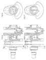
- Fig. 1 shows a side view, partially in section, of a portion of a crankshaft according to the invention,
- Figs. 2-4 show three different embodiments of one of the components in section along the line A-A in Fig. 1,
- Figs. 5 and 6 show side views, partially in section, of two additional embodiments, and
- Figs. 7 and 8 show cross sections along the line VII-VII and VIII-VIII in Figs. 5 and 6.
- The crankshaft shown in Fig. 1 is made of a number, dependent on the number of cylinders, of pairs of components 1 and 2 and end journals 3. Each component 1 and 2 has, in addition to a counterweight 4 or 5 respectively, a portion 6 or 7 respectively of a hollow main bearing
journal 8 and aportion bearing journal portions 6 and 9 of component 1 are longer than thebearing journal portions 7 and 10 of component 2 and are provided withradial bores cavities - In the components 1,
ducts 16 are drilled which connect thecavities bore 12, and an S- orU-shaped steel tube duct 16 and is sealingly joined to the edges of thebores bores 12 which communicate with thebore 13 via a pair oftube branches 19, a T-connection 20 and an L-shaped tube 21, which are sealingly joined to each other. A tight joint between the tubes and the edges of the bores can be obtained by pressure-rolling or folding of the tube ends. Alternatively, they can be welded, soldered or glued to the edges of the bores. An intermediate sealing member can possibly be used. - Figs. 5 and 7 show a simplified embodiment in which the oil duct is formed by a completely
straight tube 25, which lies in the plane of symmetry of the components. The advantage of this arrangement is that thebores duct 16 can be drilled in a single work step and that the mounting of thetube 25 will be simple. - Figs. 6 and 8 show a similar embodiment, but here the tube has been entirely eliminated and instead the
respective cavity ridge 23 which projects into the cavity from one end wall and in which abore 24 extends. Thebores 24 form unbroken transitions between thebores bore 16 in the intermediate wall. As in the immediately preceding example, this permits the bore to be drilled in a single step. - After machining and completion of the oil ducts, the required number of components 1 and 2 and two end members 3 are pressed together to form a complete crankshaft, whereafter the jointing can be done. Preferably, the components are welded together by electron-beam welding, which produces an exact welding joint without deformation and can be controlled so that the structure of the material will remain essentially unchanged. Other joining methods can also be used such as laser welding, soldering or gluing. Furthermore, other materials than steel, e.g. plastic, can be used in the tubes. To facilitate the joining together (the welding) and to obtain good precision, the bearing journals are made with
guides 22, so that the shaft can be preassembled with pressure means prior to the final jointing.
Claims (5)
Priority Applications (1)
| Application Number | Priority Date | Filing Date | Title |
|---|---|---|---|
| AT82903077T ATE25137T1 (en) | 1981-10-08 | 1982-10-07 | CRANKSHAFT FOR COMBUSTION ENGINE AND METHOD FOR MANUFACTURE. |
Applications Claiming Priority (2)
| Application Number | Priority Date | Filing Date | Title |
|---|---|---|---|
| SE8105965 | 1981-10-08 | ||
| SE8105965A SE428051B (en) | 1981-10-08 | 1981-10-08 | INCREASING ENGINE SWITCH AND SETS IN ITS MANUFACTURING |
Publications (2)
| Publication Number | Publication Date |
|---|---|
| EP0090013A1 EP0090013A1 (en) | 1983-10-05 |
| EP0090013B1 true EP0090013B1 (en) | 1987-01-21 |
Family
ID=20344740
Family Applications (1)
| Application Number | Title | Priority Date | Filing Date |
|---|---|---|---|
| EP82903077A Expired EP0090013B1 (en) | 1981-10-08 | 1982-10-07 | Crankshaft for combustion engines and method for its manufacture |
Country Status (7)
| Country | Link |
|---|---|
| US (1) | US4534241A (en) |
| EP (1) | EP0090013B1 (en) |
| JP (1) | JPS58501686A (en) |
| AT (1) | ATE25137T1 (en) |
| DE (1) | DE3275223D1 (en) |
| SE (1) | SE428051B (en) |
| WO (1) | WO1983001283A1 (en) |
Cited By (3)
| Publication number | Priority date | Publication date | Assignee | Title |
|---|---|---|---|---|
| DE19838225A1 (en) * | 1998-08-22 | 2000-03-02 | Daimler Chrysler Ag | Welded crank shaft of single elements each with crank web and tubular sections, to form main bearing journals and crank shaft journals, oil ducts and overlapping parts |
| FR2802591A1 (en) * | 1999-12-16 | 2001-06-22 | Daimler Chrysler Ag | Welded crank shaft of single elements each with crank web and tubular sections, to form main bearing journals and crank shaft journals, oil ducts and overlapping parts |
| DE102006027981A1 (en) * | 2006-06-14 | 2008-01-03 | Thyssenkrupp Gerlach Gmbh | crankshaft |
Families Citing this family (26)
| Publication number | Priority date | Publication date | Assignee | Title |
|---|---|---|---|---|
| DE3728142A1 (en) * | 1987-01-13 | 1988-08-11 | Michael Schenk | Assembled crankshaft and method for its manufacture |
| WO1989002037A1 (en) * | 1987-08-22 | 1989-03-09 | Michael Schenk | Composite crankshaft and process for manufacturing it |
| US4829642A (en) * | 1988-07-22 | 1989-05-16 | General Motors Corporation | Method of making a crankshaft |
| US5163341A (en) * | 1991-10-08 | 1992-11-17 | General Motors Corporation | Crankshaft with lubrication passages |
| DE19536349C1 (en) * | 1995-09-29 | 1997-04-30 | Porsche Ag | Crank shaft welded from single elements each with crank web |
| DE10140332C1 (en) * | 2001-08-16 | 2003-04-24 | Daimler Chrysler Ag | lightweight crankshaft |
| KR100428551B1 (en) * | 2001-12-04 | 2004-04-28 | 삼성광주전자 주식회사 | Method for manufacturing crank shaft of hermetic reciprocating compressor |
| US6874458B2 (en) | 2001-12-28 | 2005-04-05 | Kohler Co. | Balance system for single cylinder engine |
| US6739304B2 (en) | 2002-06-28 | 2004-05-25 | Kohler Co. | Cross-flow cylinder head |
| US6684846B1 (en) | 2002-07-18 | 2004-02-03 | Kohler Co. | Crankshaft oil circuit |
| US6732701B2 (en) | 2002-07-01 | 2004-05-11 | Kohler Co. | Oil circuit for twin cam internal combustion engine |
| US6837206B2 (en) | 2002-07-11 | 2005-01-04 | Kohler Co. | Crankcase cover with oil passages |
| US6752846B2 (en) * | 2002-07-18 | 2004-06-22 | Kohler Co. | Panel type air filter element with integral baffle |
| US6742488B2 (en) | 2002-07-18 | 2004-06-01 | Kohler Co. | Component for governing air flow in and around cylinder head port |
| US6978751B2 (en) | 2002-07-18 | 2005-12-27 | Kohler Co. | Cam follower arm for an internal combustion engine |
| US6837207B2 (en) | 2002-07-18 | 2005-01-04 | Kohler Co. | Inverted crankcase with attachments for an internal combustion engine |
| DE10254951B4 (en) * | 2002-11-26 | 2004-11-18 | R.A.E.-Gmbh | Cast crankshaft |
| DE102004040171B3 (en) * | 2004-08-18 | 2006-05-24 | Hubert Singer | Crankshaft for an internal combustion engine |
| US7021268B1 (en) | 2004-10-29 | 2006-04-04 | Brunswick Corporation | Crankshaft with airflow inducing surfaces |
| US7543558B2 (en) | 2004-11-10 | 2009-06-09 | Buck Diesel Engines, Inc. | Multicylinder internal combustion engine with individual cylinder assemblies |
| US7287494B2 (en) * | 2004-11-10 | 2007-10-30 | Buck Supply Co., Inc. | Multicylinder internal combustion engine with individual cylinder assemblies and modular cylinder carrier |
| US7287493B2 (en) * | 2004-11-10 | 2007-10-30 | Buck Supply Co., Inc. | Internal combustion engine with hybrid cooling system |
| USD575445S1 (en) * | 2006-06-13 | 2008-08-19 | Edward Levy | Lamp |
| JP3133309U (en) * | 2007-04-26 | 2007-07-05 | 株式会社 近藤工作所 | Crankshaft for automobile engine |
| US8316814B2 (en) | 2009-06-29 | 2012-11-27 | Buck Kenneth M | Toploading internal combustion engine |
| FR2955633B1 (en) * | 2010-01-22 | 2012-01-13 | Peugeot Citroen Automobiles Sa | HOLLOW CRANKSHAFT WITH DECAL JOINT PLAN |
Family Cites Families (15)
| Publication number | Priority date | Publication date | Assignee | Title |
|---|---|---|---|---|
| US2109526A (en) * | 1936-02-04 | 1938-03-01 | Armstrong Siddeley Motors Ltd | Built-up crankshaft |
| US2256726A (en) * | 1939-08-24 | 1941-09-23 | Gen Motors Corp | Crankshaft construction |
| DE1022426B (en) * | 1954-01-22 | 1958-01-09 | Daimler Benz Ag | Cast hollow crankshaft |
| GB846191A (en) * | 1957-08-23 | 1960-08-31 | Ford Motor Co | Hollow cast crankshafts with lubrication tubes |
| DE1216030B (en) * | 1958-04-05 | 1966-05-05 | Karl Schmidt Ges Mit Beschraen | Crankshaft with bores and channels for guiding lubricants |
| NL101443C (en) * | 1960-03-14 | |||
| US3309941A (en) * | 1965-07-15 | 1967-03-21 | James C Kappel | Sectional crankshaft |
| DE1922488A1 (en) * | 1969-05-02 | 1970-11-05 | Porsche Kg | Compound crankshaft for multi-cylinder piston engines, especially internal combustion engines |
| GB1246952A (en) * | 1969-02-08 | 1971-09-22 | Continental Gummi Werke Ag | Improvements in or relating to a method of manufacturing tyres |
| US3748925A (en) * | 1970-04-09 | 1973-07-31 | Perkins Engines Ltd | Crankshaft balance weights and method of assembly |
| HU165391B (en) * | 1970-05-13 | 1974-08-28 | ||
| US3772763A (en) * | 1971-02-17 | 1973-11-20 | Caterpillar Tractor Co | Improved lightweight crankshaft |
| DE2427801C3 (en) * | 1974-06-08 | 1979-10-11 | Maschinenfabrik Augsburg-Nuernberg Ag, 8500 Nuernberg | Crankshaft welded together from individual parts |
| JPS55107112A (en) * | 1979-02-06 | 1980-08-16 | Kubota Ltd | Structure of engine crankshaft |
| JPS57103750A (en) * | 1980-12-19 | 1982-06-28 | Toyota Motor Corp | Crankshaft material made from steel plate and its production |
-
1981
- 1981-10-08 SE SE8105965A patent/SE428051B/en not_active IP Right Cessation
-
1982
- 1982-10-07 DE DE8282903077T patent/DE3275223D1/en not_active Expired
- 1982-10-07 JP JP57503090A patent/JPS58501686A/en active Pending
- 1982-10-07 WO PCT/SE1982/000323 patent/WO1983001283A1/en not_active Ceased
- 1982-10-07 US US06/503,193 patent/US4534241A/en not_active Expired - Fee Related
- 1982-10-07 EP EP82903077A patent/EP0090013B1/en not_active Expired
- 1982-10-07 AT AT82903077T patent/ATE25137T1/en not_active IP Right Cessation
Cited By (4)
| Publication number | Priority date | Publication date | Assignee | Title |
|---|---|---|---|---|
| DE19838225A1 (en) * | 1998-08-22 | 2000-03-02 | Daimler Chrysler Ag | Welded crank shaft of single elements each with crank web and tubular sections, to form main bearing journals and crank shaft journals, oil ducts and overlapping parts |
| DE19838225B4 (en) * | 1998-08-22 | 2005-10-20 | Daimler Chrysler Ag | Welded crankshaft |
| FR2802591A1 (en) * | 1999-12-16 | 2001-06-22 | Daimler Chrysler Ag | Welded crank shaft of single elements each with crank web and tubular sections, to form main bearing journals and crank shaft journals, oil ducts and overlapping parts |
| DE102006027981A1 (en) * | 2006-06-14 | 2008-01-03 | Thyssenkrupp Gerlach Gmbh | crankshaft |
Also Published As
| Publication number | Publication date |
|---|---|
| EP0090013A1 (en) | 1983-10-05 |
| US4534241A (en) | 1985-08-13 |
| WO1983001283A1 (en) | 1983-04-14 |
| SE8105965L (en) | 1983-04-09 |
| SE428051B (en) | 1983-05-30 |
| JPS58501686A (en) | 1983-10-06 |
| ATE25137T1 (en) | 1987-02-15 |
| DE3275223D1 (en) | 1987-02-26 |
Similar Documents
| Publication | Publication Date | Title |
|---|---|---|
| US4534241A (en) | Crankshaft for combustion engines | |
| FR2578463A1 (en) | PROCESS FOR THE PRODUCTION OF A COMPOSITE CAM SHAFT | |
| CN100516592C (en) | Differential axes of coordinates for a differential gear | |
| HU186223B (en) | Hollow shaft and mezhod for producing same | |
| KR890000687B1 (en) | Method of manufacturing a rotor for rotary fluid pump | |
| US4550480A (en) | Method of producing scroll type compressor | |
| KR20100016374A (en) | Crankshaft for automobile engine | |
| US4556532A (en) | Method for manufacturing camshaft | |
| JPH04134104A (en) | Rocker shaft | |
| US5265566A (en) | Assembled seal disc for a crankshaft | |
| US5588405A (en) | Arrangement of oil passage to valve system | |
| US3768335A (en) | Crankshaft composed of a plurality of sections welded together | |
| CA1303877C (en) | Process for producing crankshafts | |
| CN1026559C (en) | Method for producing a crankshaft by expanding a sleeve on a separate journal | |
| GB2167524A (en) | Camshafts for internal combustion engines | |
| US4008927A (en) | Crank shaft welded together from individual elements | |
| JPH025704A (en) | Intake/exhaust valve for engine and manufacture thereof | |
| US5197188A (en) | Process for producing assembled crankshafts by expanding sleeves arranged in divided journals | |
| JPS63219890A (en) | Combined crankshaft for rotary compressor | |
| CN102712032B (en) | Hollow crankshaft with offset joint planes | |
| JPH027210Y2 (en) | ||
| JPS62177357A (en) | Cam piece having oil port and manufacture thereof | |
| JPH02501156A (en) | Assembly type crankshaft and its manufacturing method | |
| JPH02180308A (en) | Cast crank shaft for internal combustion engine | |
| KR810001456B1 (en) | Crank shaft welded together from individual elements |
Legal Events
| Date | Code | Title | Description |
|---|---|---|---|
| PUAI | Public reference made under article 153(3) epc to a published international application that has entered the european phase |
Free format text: ORIGINAL CODE: 0009012 |
|
| AK | Designated contracting states |
Designated state(s): AT BE DE FR GB NL |
|
| 17P | Request for examination filed |
Effective date: 19831007 |
|
| GRAA | (expected) grant |
Free format text: ORIGINAL CODE: 0009210 |
|
| AK | Designated contracting states |
Kind code of ref document: B1 Designated state(s): AT BE DE FR GB NL |
|
| REF | Corresponds to: |
Ref document number: 25137 Country of ref document: AT Date of ref document: 19870215 Kind code of ref document: T |
|
| REF | Corresponds to: |
Ref document number: 3275223 Country of ref document: DE Date of ref document: 19870226 |
|
| PLBE | No opposition filed within time limit |
Free format text: ORIGINAL CODE: 0009261 |
|
| STAA | Information on the status of an ep patent application or granted ep patent |
Free format text: STATUS: NO OPPOSITION FILED WITHIN TIME LIMIT |
|
| 26N | No opposition filed | ||
| PGFP | Annual fee paid to national office [announced via postgrant information from national office to epo] |
Ref country code: GB Payment date: 19920928 Year of fee payment: 11 |
|
| PGFP | Annual fee paid to national office [announced via postgrant information from national office to epo] |
Ref country code: FR Payment date: 19921005 Year of fee payment: 11 |
|
| PGFP | Annual fee paid to national office [announced via postgrant information from national office to epo] |
Ref country code: AT Payment date: 19921014 Year of fee payment: 11 |
|
| PGFP | Annual fee paid to national office [announced via postgrant information from national office to epo] |
Ref country code: DE Payment date: 19921021 Year of fee payment: 11 |
|
| PGFP | Annual fee paid to national office [announced via postgrant information from national office to epo] |
Ref country code: BE Payment date: 19921028 Year of fee payment: 11 |
|
| PGFP | Annual fee paid to national office [announced via postgrant information from national office to epo] |
Ref country code: NL Payment date: 19921031 Year of fee payment: 11 |
|
| PG25 | Lapsed in a contracting state [announced via postgrant information from national office to epo] |
Ref country code: GB Effective date: 19931007 Ref country code: AT Effective date: 19931007 |
|
| PG25 | Lapsed in a contracting state [announced via postgrant information from national office to epo] |
Ref country code: BE Effective date: 19931031 |
|
| BERE | Be: lapsed |
Owner name: AB VOLVO Effective date: 19931031 |
|
| PG25 | Lapsed in a contracting state [announced via postgrant information from national office to epo] |
Ref country code: NL Effective date: 19940501 |
|
| GBPC | Gb: european patent ceased through non-payment of renewal fee |
Effective date: 19931007 |
|
| NLV4 | Nl: lapsed or anulled due to non-payment of the annual fee | ||
| PG25 | Lapsed in a contracting state [announced via postgrant information from national office to epo] |
Ref country code: FR Effective date: 19940630 |
|
| PG25 | Lapsed in a contracting state [announced via postgrant information from national office to epo] |
Ref country code: DE Effective date: 19940701 |
|
| REG | Reference to a national code |
Ref country code: FR Ref legal event code: ST |