EP0089433A1 - Secondary battery - Google Patents
Secondary battery Download PDFInfo
- Publication number
- EP0089433A1 EP0089433A1 EP82301560A EP82301560A EP0089433A1 EP 0089433 A1 EP0089433 A1 EP 0089433A1 EP 82301560 A EP82301560 A EP 82301560A EP 82301560 A EP82301560 A EP 82301560A EP 0089433 A1 EP0089433 A1 EP 0089433A1
- Authority
- EP
- European Patent Office
- Prior art keywords
- catholyte
- outlet
- inlet
- cathode
- anolyte
- Prior art date
- Legal status (The legal status is an assumption and is not a legal conclusion. Google has not performed a legal analysis and makes no representation as to the accuracy of the status listed.)
- Granted
Links
Images


Classifications
-
- H—ELECTRICITY
- H01—ELECTRIC ELEMENTS
- H01M—PROCESSES OR MEANS, e.g. BATTERIES, FOR THE DIRECT CONVERSION OF CHEMICAL ENERGY INTO ELECTRICAL ENERGY
- H01M10/00—Secondary cells; Manufacture thereof
- H01M10/42—Methods or arrangements for servicing or maintenance of secondary cells or secondary half-cells
- H01M10/4214—Arrangements for moving electrodes or electrolyte
-
- H—ELECTRICITY
- H01—ELECTRIC ELEMENTS
- H01M—PROCESSES OR MEANS, e.g. BATTERIES, FOR THE DIRECT CONVERSION OF CHEMICAL ENERGY INTO ELECTRICAL ENERGY
- H01M50/00—Constructional details or processes of manufacture of the non-active parts of electrochemical cells other than fuel cells, e.g. hybrid cells
- H01M50/70—Arrangements for stirring or circulating the electrolyte
- H01M50/77—Arrangements for stirring or circulating the electrolyte with external circulating path
-
- Y—GENERAL TAGGING OF NEW TECHNOLOGICAL DEVELOPMENTS; GENERAL TAGGING OF CROSS-SECTIONAL TECHNOLOGIES SPANNING OVER SEVERAL SECTIONS OF THE IPC; TECHNICAL SUBJECTS COVERED BY FORMER USPC CROSS-REFERENCE ART COLLECTIONS [XRACs] AND DIGESTS
- Y02—TECHNOLOGIES OR APPLICATIONS FOR MITIGATION OR ADAPTATION AGAINST CLIMATE CHANGE
- Y02E—REDUCTION OF GREENHOUSE GAS [GHG] EMISSIONS, RELATED TO ENERGY GENERATION, TRANSMISSION OR DISTRIBUTION
- Y02E60/00—Enabling technologies; Technologies with a potential or indirect contribution to GHG emissions mitigation
- Y02E60/10—Energy storage using batteries
Definitions
- the present invention relates to a circulating electrolyte type of a cell stack secondary battery in which the negatively active material is cadmium, zinc, lead or the like, and more particularly the invention relates to such a secondary battery designed to prevent the occurrence of any abnormal electrodeposition due to small shunt current.
- Known - cell stack secondary batteries of the above type generally comprise a plurality of secondary cells connected in series electrically and respective electrolytes are supplied to the cathode and anode chambers of each secondary cell through a catholyte inlet-side common manifold or a anolyte inlet-side common manifold and the catholyte inlet channel or the anolyte inlet channel of each cell, leaving each cell through respective catholyte outlet channels and anolyte outlet channels and respective catholyte outlet-side common manifolds and anolyte outlet-side common manifolds.
- a method is known in the art in which the manifolds and the channels are decreased in diameter and increased in length, thus increasing the electric resistance of the electrolytes in the manifolds and the channels, and thereby decreasing the value of the shunt currents.
- This method does have the effect of decreasing the shunt current value and reducing some of the previously mentioned difficulties due to the shunt current, i.e., the shunt current loss and the inequality of quantity of charged electricity. Even if the shunt current value is decreased, however, the shunt current flows in the same direction during the charging period as well as the discharging period.
- the present invention provides an improved secondary battery in which an additional electrode is provided in and/or near each of the catholyte manifolds and/or channels of each secondary cell, and each additional electrode is connected to the respective associated cathode by means of a conductive material.
- an additional electrode is provided in and/or near each of the catholyte manifolds and/or channels of each secondary cell, and each additional electrode is connected to the respective associated cathode by means of a conductive material.
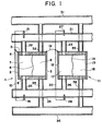
- a cell stack battery according to the invention will include, for example, 10 secondary cells connected in series, although only two cells 1 and 11 are shown in the Figure.
- Numeral 2 designates a cathode, 3 an anode, and 4 a separator positioned substantially halfway between the electrodes 2 and 3. These elements are held together with bolts or the like by means of electrode frames 5 and 6.
- Numeral 7 designates a cathode chamber, 8 an anode chamber, and 9 a terminal of the cell l.
- the anode 3 of the cell 1 is connected to a cathode 12 of the adjoining secondary cell 11 by a connector 19.
- a connector 19 Of course, in the case of a bipolar type cell stack battery it is only necessary to use one or the other of the anode and cathode 3 and 12 which are of the same potential, and arrange the cells 1 and 11 in stacks.
- Numeral 21 designates a catholyte inlet-side common manifold, connected by respective catholyte inlet channels 22 and 23 to cathode chambers 7 and 17.
- Numeral 24 designates a catholyte outlet-side common manifold, connected to cathode chambers 7 and 17 by respective catholyte outlet channels 25 and 26.
- numeral 31 designates an anolyte inlet-side common manifold, 32 and 33 anolyte inlet channels, 34 an anolyte outlet-side common manifold, and 35 and 36 anolyte outlet channels.
- the inlet channels 22, 32, 23 and 33 and the outlet channels 25, 35, 26 and 36 run in a direction perpendicular to the cell stack direction of the electrode frames 5 and 6, and are arranged side by side along the top and bottom electrode frames 5 and 6.
- the cell stack battery constructed as described above is thus far identical with the prior art battery.
- the catholyte is introduced by a pump (not shown) via the inlet-side common manifold 21 and the inlet channels 22 and 23 into the cathode chambers 7 and 17 of the cells 1 and 11, and thence passes into the outlet-side common manifold 24 via the outlet channels 25 and 26.
- the anolyte is introduced by a pump (not shown) via the inlet side-common manifold 31 and the inlet channels 32 and 33 into the anode chambers 8 and 18 of the cells 1 and 11, and thence passes into the outlet-side common manifold 34 via the outlet channels 35 and 36.
- the cell stack battery constructed as described is further provided with electrodes 15, 16 and 27, 28 which are respectively disposed in the electrolytes of the catholyte inlet-side and outlet-side common manifolds 21 and 24. Electrodes 15 and 16 are respectively hermetically fitted into those portions of the inlet-side common manifold 21 and the outlet-side common manifold 24 which communicate with the cathode chamber 7 of the end cell 1. Similarly, electrodes 27 and 28 are respectively hermetically fitted into those portions of the inlet-side common manifold 21 and the outlet-side common manifold 24 which communicate with the cathode chamber 17 of the cell 11.
- Electrodes 15 and 16 are connected to the terminal 9 by a connector 10 and are thus held at the same potential as the cathode 2.
- electrodes 27 and 28 are connected to the connector 19 by a connector 20, and are thus held at the same potential as the cathode 12 of the cell 11.
- Fig. 2 illustrates characteristic diagrams showing the results of shunt current measurements on charge in instances (spots 0) where the invention was applied to secondary batteries comprising 10 secondary cells, and instances (spots 8) where the invention was not applied, with (a) showing the currents at the catholyte inlets, (b) those at the anolyte inlets, (c) those at the catholyte outlets and (d) those at the anolyte outlets.
- the ordinates represent the shunt current value (mA) and the positive and negative values respectively represent the shunt current flowing from the cathode or anode chamber into the manifold through the channel and the shunt current flowing into the cathode or anode chamber from the manifold through the channel.
- the abscissae represent the channel positions of the respective cells.
- the electrodes 15, 16, 27 and 28 are fitted into the inlet-side and outlet-side common manifolds 21 and 24, these electrodes 15, 16, 27 and 28 may be respectively positioned near the inlet and outlet channels which communicate with the cathode chambers of the stacked secondary cells.
- Fig. 3 shows another embodiment of the invention. This embodiment differs from the embodiment described in connection with Fig. 1 in that pipes 40 and 41 are provided near the junction points between the catholyte inlet-side common manifold 21 and the catholyte inlet channels 22 and 23 for connecting the catholyte inlet-side common manifold 21 to the anolyte inlet-side common manifold 31. Similarly, pipes 42 and 43 are provided between the catholyte outlet-side common manifold 24 and the catholyte outlet channels 25 and 26, for connecting the catholyte outlet-side common manifold 24 to the anolyte outlet-side common manifold 34.
- Separators 44, 45, 46 and 47 are respectively disposed in the pipes 40, 41, 42 and 43 to prevent mixing of the catholyte and anolyte, and the electrodes 15, 16, 27 and 28 are respectively disposed according to the invention in the anolyte in these pipes.
- Each of these separators transmits ions but prevents the transmission of electrolyte.
- the electrodes 15, 16, 27 and 28 are respectively hermetically fitted into the anolyte side of pipes 40, 41, 42 and 43 which are separated by the separators 44, 45, 46 and 47, respectively. Electrodes 15 and 16 are connected to the terminal 9 by the connector 10 and held at the same potential as the cathode 2.
- Electrodes 27 and 28 are connected to the connector 19 by the connector 20 and held at the same potential as the cathode 12. In this way, the same effect as in the arrangement of Fig. 1 can be obtained with the arrangement of the electrodes 15, 16, 27 and 28 shown in Fig. 3. Still further, in contrast to the first embodiment in which the electrodes 15, 16, 27 and 28 are fitted into the catholyte inlet and outlet common manifolds, the deposition of the metal of the negatively active material on the cathodes is prevented.
- the occurrence of abnormal electrodeposition can be prevented and the cycle life can be increased by virtue of the fact that an electrode is provided in the vicinity of each of the inlet and outlet of a cathode chamber of each secondary battery and the potential of these electrodes is held equal to that of the associated cathode, thereby absorbing the small shunt currents which cause abnormal electrodeposition.
Landscapes
- Chemical & Material Sciences (AREA)
- Chemical Kinetics & Catalysis (AREA)
- Electrochemistry (AREA)
- General Chemical & Material Sciences (AREA)
- Engineering & Computer Science (AREA)
- Manufacturing & Machinery (AREA)
- Hybrid Cells (AREA)
Abstract
Description
- The present invention relates to a circulating electrolyte type of a cell stack secondary battery in which the negatively active material is cadmium, zinc, lead or the like, and more particularly the invention relates to such a secondary battery designed to prevent the occurrence of any abnormal electrodeposition due to small shunt current.
- Known - cell stack secondary batteries of the above type generally comprise a plurality of secondary cells connected in series electrically and respective electrolytes are supplied to the cathode and anode chambers of each secondary cell through a catholyte inlet-side common manifold or a anolyte inlet-side common manifold and the catholyte inlet channel or the anolyte inlet channel of each cell, leaving each cell through respective catholyte outlet channels and anolyte outlet channels and respective catholyte outlet-side common manifolds and anolyte outlet-side common manifolds. With secondary cells connected in series in this way, the circulation of the electolytes is effected in a so-called parallel connection, so that a small shunt current is caused at the inlet and outlet sides of each cell via the common manifolds by the potential difference between the plurality of the cell stack anodes and cathodes. This gives rise to the following undesirable phenomena:
- (1) Shunt current loss:
- A loss of heat is caused by the small shunt current through the manifolds and the channels.
- (2) Inequality of quantity of charged electricity:
- Due to the' difference in the current value (mA) of the small shunt current flowing into and out of the channels of the respective cells, the currents flowing in the electrodes of the respective cells differ in value from one cell to another, with the result that the amount of negatively active metal electro-deposited on the cathode surface and/or the quantity of charged electricity differs from one cell to another.
- (3) Occurrence of abnormal electrodeposition:
- At the end of each cathode of the lower potential side respectively, into which a small current flows, even a slight shunt current causes abnormal electrodeposition due to the end concentration of the cathode, thus disturbing the circulation of the electrolyte on the cathode surface and/or causing a short-circuit between adjacent cathodes.
- To overcome these detrimental effects, various methods have heretofore been proposed.
- For instance, a method is known in the art in which the manifolds and the channels are decreased in diameter and increased in length, thus increasing the electric resistance of the electrolytes in the manifolds and the channels, and thereby decreasing the value of the shunt currents. This method does have the effect of decreasing the shunt current value and reducing some of the previously mentioned difficulties due to the shunt current, i.e., the shunt current loss and the inequality of quantity of charged electricity. Even if the shunt current value is decreased, however, the shunt current flows in the same direction during the charging period as well as the discharging period. This has the result that abnormal electrodeposition is caused as the cycle of charge and discharge is repeated, and thus the circulation of the electrolytes is impeded and/or a short-circuit is caused between the respective cells, thereby causing a short endurance to the cycle life. Further, the loss of hydrostatic pressure for the circulation of the electrolytes is increased, making it necessary to use more powerful pumps for circulating the electrolytes.
- With a view to overcoming the foregoing deficiencies in the prior art, particularly the occurrence of abnormal electrodeposition without increasing the power of electrolyte circulating pumps, the present invention provides an improved secondary battery in which an additional electrode is provided in and/or near each of the catholyte manifolds and/or channels of each secondary cell, and each additional electrode is connected to the respective associated cathode by means of a conductive material. Thus, small currents flowing into the cathode chamber of the cell are absorbed by these electrodes, thereby preventing the occurrence of abnormal electrodeposition due to the entry of any shunt current and increasing the cycle life.
- The invention -is further described -with reference to the accompanying Drawings, in which:
- Fig. 1 is a longitudinal sectional view showing an embodiment of a secondary battery according to the invention;
- Figs. 2 (a), (b), (c) and (d) are each a characteristic diagram comparatively showing the values of shunt current flow into the electrolyte inlet and outlet of secondary cells during the charging period, with and without the application of the invention.
- Fig. 3 is a longitudinal sectional view showing another embodiment of the invention.
- Referring to Fig. 1,
numerals 1 and 11 designate secondary cells. A cell stack battery according to the invention will include, for example, 10 secondary cells connected in series, although only twocells 1 and 11 are shown in the Figure. Numeral 2 designates a cathode, 3 an anode, and 4 a separator positioned substantially halfway between theelectrodes electrode frames anode 3 of the cell 1 is connected to acathode 12 of the adjoiningsecondary cell 11 by aconnector 19. Of course, in the case of a bipolar type cell stack battery it is only necessary to use one or the other of the anode andcathode cells 1 and 11 in stacks. - Numeral 21 designates a catholyte inlet-side common manifold, connected by respective
catholyte inlet channels cathode chambers cathode chambers catholyte outlet channels numeral 31 designates an anolyte inlet-side common manifold, 32 and 33 anolyte inlet channels, 34 an anolyte outlet-side common manifold, and 35 and 36 anolyte outlet channels. Theinlet channels outlet channels electrode frames bottom electrode frames - The cell stack battery constructed as described above is thus far identical with the prior art battery. The catholyte is introduced by a pump (not shown) via the inlet-side
common manifold 21 and theinlet channels cathode chambers cells 1 and 11, and thence passes into the outlet-sidecommon manifold 24 via theoutlet channels common manifold 31 and theinlet channels anode chambers cells 1 and 11, and thence passes into the outlet-sidecommon manifold 34 via theoutlet channels - In accordance with the present invention, the cell stack battery constructed as described is further provided with
electrodes common manifolds Electrodes common manifold 21 and the outlet-sidecommon manifold 24 which communicate with thecathode chamber 7 of the end cell 1. Similarly,electrodes common manifold 21 and the outlet-sidecommon manifold 24 which communicate with thecathode chamber 17 of thecell 11.Electrodes terminal 9 by aconnector 10 and are thus held at the same potential as thecathode 2. Similarly,electrodes connector 19 by aconnector 20, and are thus held at the same potential as thecathode 12 of thecell 11. - Fig. 2 illustrates characteristic diagrams showing the results of shunt current measurements on charge in instances (spots 0) where the invention was applied to secondary batteries comprising 10 secondary cells, and instances (spots 8) where the invention was not applied, with (a) showing the currents at the catholyte inlets, (b) those at the anolyte inlets, (c) those at the catholyte outlets and (d) those at the anolyte outlets. In the characteristic diagrams, the ordinates represent the shunt current value (mA) and the positive and negative values respectively represent the shunt current flowing from the cathode or anode chamber into the manifold through the channel and the shunt current flowing into the cathode or anode chamber from the manifold through the channel. The abscissae represent the channel positions of the respective cells.
- These tests were conducted by measuring the shunt currents of the respective channels with a clip-on ammeter and the values were measured at the expiration of 90 to 100 minutes after starting the charge with a charging voltage of 22 V and a charging current of 12 A. As will be apparent from (a) and (c) of Fig. 2, there was a small current flow into the cathode chambers without the application of the invention, and this small current flow was eliminated when the invention was applied.
- When the tests were continued . further and then the batteries were disassembled after the lapse of 25 hours through the cycles of charge and discharge to compare the electrodeposition of the zinc on the cathode surfaces, the occurrence of dendritic electrodeposition of the zinc on the cathodes near the channels was seen when the invention was not applied, and there was no such abnormal electrodeposition when the invention was applied.
- While, in the embodiment described above, the
electrodes common manifolds electrodes - Fig. 3 shows another embodiment of the invention. This embodiment differs from the embodiment described in connection with Fig. 1 in that
pipes common manifold 21 and thecatholyte inlet channels common manifold 21 to the anolyte inlet-sidecommon manifold 31. Similarly,pipes common manifold 24 and thecatholyte outlet channels common manifold 24 to the anolyte outlet-sidecommon manifold 34.Separators pipes electrodes electrodes pipes separators Electrodes terminal 9 by theconnector 10 and held at the same potential as thecathode 2.Electrodes connector 19 by theconnector 20 and held at the same potential as thecathode 12. In this way, the same effect as in the arrangement of Fig. 1 can be obtained with the arrangement of theelectrodes electrodes - From the foregoing detailed description it will be seen that in accordance with the cell stack secondary battery of this invention the occurrence of abnormal electrodeposition can be prevented and the cycle life can be increased by virtue of the fact that an electrode is provided in the vicinity of each of the inlet and outlet of a cathode chamber of each secondary battery and the potential of these electrodes is held equal to that of the associated cathode, thereby absorbing the small shunt currents which cause abnormal electrodeposition.
Claims (5)
Priority Applications (2)
| Application Number | Priority Date | Filing Date | Title |
|---|---|---|---|
| EP82301560A EP0089433B1 (en) | 1982-03-24 | 1982-03-24 | Secondary battery |
| DE8282301560T DE3273274D1 (en) | 1982-03-24 | 1982-03-24 | Secondary battery |
Applications Claiming Priority (1)
| Application Number | Priority Date | Filing Date | Title |
|---|---|---|---|
| EP82301560A EP0089433B1 (en) | 1982-03-24 | 1982-03-24 | Secondary battery |
Publications (2)
| Publication Number | Publication Date |
|---|---|
| EP0089433A1 true EP0089433A1 (en) | 1983-09-28 |
| EP0089433B1 EP0089433B1 (en) | 1986-09-17 |
Family
ID=8189618
Family Applications (1)
| Application Number | Title | Priority Date | Filing Date |
|---|---|---|---|
| EP82301560A Expired EP0089433B1 (en) | 1982-03-24 | 1982-03-24 | Secondary battery |
Country Status (2)
| Country | Link |
|---|---|
| EP (1) | EP0089433B1 (en) |
| DE (1) | DE3273274D1 (en) |
Cited By (3)
| Publication number | Priority date | Publication date | Assignee | Title |
|---|---|---|---|---|
| EP0207057A3 (en) * | 1985-05-23 | 1987-09-09 | S.E.A. Studiengesellschaft für Energiespeicher und Antriebssysteme Gesellschaft m.b.H. | Galvanic element, for example a zinc-bromine battery |
| EP0093213B1 (en) * | 1982-05-04 | 1987-09-09 | Kabushiki Kaisha Meidensha | Electrolytes circulation type cell stack secondary battery |
| US8293390B2 (en) | 2007-03-28 | 2012-10-23 | Redflow Pty Ltd | Cell stack for a flowing electrolyte battery |
Citations (2)
| Publication number | Priority date | Publication date | Assignee | Title |
|---|---|---|---|---|
| EP0029680A1 (en) * | 1979-11-14 | 1981-06-03 | Meidensha Electric Mfg. Co., Ltd. | Metal-halogen secondary battery system |
| EP0034492A2 (en) * | 1980-02-19 | 1981-08-26 | Exxon Research And Engineering Company | Electrochemical device having means for reducing shunt current |
-
1982
- 1982-03-24 EP EP82301560A patent/EP0089433B1/en not_active Expired
- 1982-03-24 DE DE8282301560T patent/DE3273274D1/en not_active Expired
Patent Citations (2)
| Publication number | Priority date | Publication date | Assignee | Title |
|---|---|---|---|---|
| EP0029680A1 (en) * | 1979-11-14 | 1981-06-03 | Meidensha Electric Mfg. Co., Ltd. | Metal-halogen secondary battery system |
| EP0034492A2 (en) * | 1980-02-19 | 1981-08-26 | Exxon Research And Engineering Company | Electrochemical device having means for reducing shunt current |
Cited By (5)
| Publication number | Priority date | Publication date | Assignee | Title |
|---|---|---|---|---|
| EP0093213B1 (en) * | 1982-05-04 | 1987-09-09 | Kabushiki Kaisha Meidensha | Electrolytes circulation type cell stack secondary battery |
| EP0207057A3 (en) * | 1985-05-23 | 1987-09-09 | S.E.A. Studiengesellschaft für Energiespeicher und Antriebssysteme Gesellschaft m.b.H. | Galvanic element, for example a zinc-bromine battery |
| AT389598B (en) * | 1985-05-23 | 1989-12-27 | Energiespeicher & Antriebssyst | GALVANIC ELEMENT, IF NECESSARY ZINC / BROMBATTERIE |
| US8293390B2 (en) | 2007-03-28 | 2012-10-23 | Redflow Pty Ltd | Cell stack for a flowing electrolyte battery |
| CN101647138B (en) * | 2007-03-28 | 2012-11-14 | 红流私人有限公司 | Cell stack for a flowing electrolyte battery |
Also Published As
| Publication number | Publication date |
|---|---|
| DE3273274D1 (en) | 1986-10-23 |
| EP0089433B1 (en) | 1986-09-17 |
Similar Documents
| Publication | Publication Date | Title |
|---|---|---|
| US3666561A (en) | Electrolyte circulating battery | |
| SU1486068A3 (en) | Comb-like bipolar cell of storage battery with circulating electrolyte and electrode assembly therefor | |
| EP3553864B1 (en) | Bipolar plate, cell stack, and redox flow battery | |
| EP0165000B1 (en) | Metal-halogen secondary battery | |
| JPH02216772A (en) | Zinc-bromine battery | |
| US20240120625A1 (en) | Cylindrical battery cell, battery and method for forming cylindrical battery cell | |
| CA2085139C (en) | Method of operating metal-halogen battery | |
| US4416953A (en) | Secondary battery | |
| EP0089433A1 (en) | Secondary battery | |
| KR102645988B1 (en) | Bipolar plate and unit cell for redox flow cell battery and redox flow battery comprising the same | |
| KR101807378B1 (en) | Electrochemical device and method for controlling corrosion | |
| US4520080A (en) | Electrolytes circulation type cell stack secondary battery | |
| EP0093213B1 (en) | Electrolytes circulation type cell stack secondary battery | |
| EP0208358B1 (en) | Battery stack of secondary cells | |
| CA1165810A (en) | Secondary battery | |
| EP0109727A2 (en) | Electrochemical device | |
| JPH0159707B2 (en) | ||
| JP2931650B2 (en) | Electrolyte circulation type secondary battery | |
| RU2233014C2 (en) | Composite structure for storage-battery cell | |
| JPH021354B2 (en) | ||
| JPH0449757B2 (en) | ||
| KR102283441B1 (en) | A Battery Cell for Redox flow battery having a mixed serial and parallel structure | |
| WO2025108690A1 (en) | Method for operating an iron salt battery | |
| JPH024108B2 (en) | ||
| JPH0131671B2 (en) |
Legal Events
| Date | Code | Title | Description |
|---|---|---|---|
| PUAI | Public reference made under article 153(3) epc to a published international application that has entered the european phase |
Free format text: ORIGINAL CODE: 0009012 |
|
| AK | Designated contracting states |
Designated state(s): DE FR GB IT |
|
| 17P | Request for examination filed |
Effective date: 19840114 |
|
| ITF | It: translation for a ep patent filed | ||
| GRAA | (expected) grant |
Free format text: ORIGINAL CODE: 0009210 |
|
| AK | Designated contracting states |
Kind code of ref document: B1 Designated state(s): DE FR GB IT |
|
| REF | Corresponds to: |
Ref document number: 3273274 Country of ref document: DE Date of ref document: 19861023 |
|
| ET | Fr: translation filed | ||
| PLBE | No opposition filed within time limit |
Free format text: ORIGINAL CODE: 0009261 |
|
| 26N | No opposition filed | ||
| ITTA | It: last paid annual fee | ||
| PGFP | Annual fee paid to national office [announced via postgrant information from national office to epo] |
Ref country code: FR Payment date: 19960131 Year of fee payment: 15 |
|
| PGFP | Annual fee paid to national office [announced via postgrant information from national office to epo] |
Ref country code: GB Payment date: 19960313 Year of fee payment: 15 |
|
| PGFP | Annual fee paid to national office [announced via postgrant information from national office to epo] |
Ref country code: DE Payment date: 19960425 Year of fee payment: 15 |
|
| PG25 | Lapsed in a contracting state [announced via postgrant information from national office to epo] |
Ref country code: GB Effective date: 19970324 |
|
| GBPC | Gb: european patent ceased through non-payment of renewal fee |
Effective date: 19970324 |
|
| PG25 | Lapsed in a contracting state [announced via postgrant information from national office to epo] |
Ref country code: FR Free format text: LAPSE BECAUSE OF NON-PAYMENT OF DUE FEES Effective date: 19971128 |
|
| PG25 | Lapsed in a contracting state [announced via postgrant information from national office to epo] |
Ref country code: DE Effective date: 19971202 |
|
| REG | Reference to a national code |
Ref country code: FR Ref legal event code: ST |