EP0089286A2 - Liquid spring accumulator with self-charging means - Google Patents
Liquid spring accumulator with self-charging means Download PDFInfo
- Publication number
- EP0089286A2 EP0089286A2 EP83400509A EP83400509A EP0089286A2 EP 0089286 A2 EP0089286 A2 EP 0089286A2 EP 83400509 A EP83400509 A EP 83400509A EP 83400509 A EP83400509 A EP 83400509A EP 0089286 A2 EP0089286 A2 EP 0089286A2
- Authority
- EP
- European Patent Office
- Prior art keywords
- piston
- high pressure
- liquid
- check valve
- pressure chamber
- Prior art date
- Legal status (The legal status is an assumption and is not a legal conclusion. Google has not performed a legal analysis and makes no representation as to the accuracy of the status listed.)
- Granted
Links
Images

Classifications
-
- F—MECHANICAL ENGINEERING; LIGHTING; HEATING; WEAPONS; BLASTING
- F15—FLUID-PRESSURE ACTUATORS; HYDRAULICS OR PNEUMATICS IN GENERAL
- F15B—SYSTEMS ACTING BY MEANS OF FLUIDS IN GENERAL; FLUID-PRESSURE ACTUATORS, e.g. SERVOMOTORS; DETAILS OF FLUID-PRESSURE SYSTEMS, NOT OTHERWISE PROVIDED FOR
- F15B1/00—Installations or systems with accumulators; Supply reservoir or sump assemblies
- F15B1/02—Installations or systems with accumulators
- F15B1/04—Accumulators
-
- F—MECHANICAL ENGINEERING; LIGHTING; HEATING; WEAPONS; BLASTING
- F15—FLUID-PRESSURE ACTUATORS; HYDRAULICS OR PNEUMATICS IN GENERAL
- F15B—SYSTEMS ACTING BY MEANS OF FLUIDS IN GENERAL; FLUID-PRESSURE ACTUATORS, e.g. SERVOMOTORS; DETAILS OF FLUID-PRESSURE SYSTEMS, NOT OTHERWISE PROVIDED FOR
- F15B2201/00—Accumulators
- F15B2201/20—Accumulator cushioning means
- F15B2201/21—Accumulator cushioning means using springs
-
- F—MECHANICAL ENGINEERING; LIGHTING; HEATING; WEAPONS; BLASTING
- F15—FLUID-PRESSURE ACTUATORS; HYDRAULICS OR PNEUMATICS IN GENERAL
- F15B—SYSTEMS ACTING BY MEANS OF FLUIDS IN GENERAL; FLUID-PRESSURE ACTUATORS, e.g. SERVOMOTORS; DETAILS OF FLUID-PRESSURE SYSTEMS, NOT OTHERWISE PROVIDED FOR
- F15B2201/00—Accumulators
- F15B2201/30—Accumulator separating means
- F15B2201/31—Accumulator separating means having rigid separating means, e.g. pistons
- F15B2201/312—Sealings therefor, e.g. piston rings
-
- F—MECHANICAL ENGINEERING; LIGHTING; HEATING; WEAPONS; BLASTING
- F15—FLUID-PRESSURE ACTUATORS; HYDRAULICS OR PNEUMATICS IN GENERAL
- F15B—SYSTEMS ACTING BY MEANS OF FLUIDS IN GENERAL; FLUID-PRESSURE ACTUATORS, e.g. SERVOMOTORS; DETAILS OF FLUID-PRESSURE SYSTEMS, NOT OTHERWISE PROVIDED FOR
- F15B2201/00—Accumulators
- F15B2201/40—Constructional details of accumulators not otherwise provided for
- F15B2201/41—Liquid ports
- F15B2201/411—Liquid ports having valve means
-
- F—MECHANICAL ENGINEERING; LIGHTING; HEATING; WEAPONS; BLASTING
- F15—FLUID-PRESSURE ACTUATORS; HYDRAULICS OR PNEUMATICS IN GENERAL
- F15B—SYSTEMS ACTING BY MEANS OF FLUIDS IN GENERAL; FLUID-PRESSURE ACTUATORS, e.g. SERVOMOTORS; DETAILS OF FLUID-PRESSURE SYSTEMS, NOT OTHERWISE PROVIDED FOR
- F15B2201/00—Accumulators
- F15B2201/40—Constructional details of accumulators not otherwise provided for
- F15B2201/41—Liquid ports
- F15B2201/413—Liquid ports having multiple liquid ports
Definitions
- This invention relates to a liquid spring accumulator with self-charging means.
- a liquid spring accumulator includes a high strength housing having inlet and return ports communicating with a source of liquid under high pressure and incorporating a high pressure chamber and a cylindrical chamber containing a piston communicating on one side with said source of liquid under high pressure and on its other side with the return side of said source and with a resilient member which urges the piston toward said inlet port.
- a rod of substantially smaller area than said piston and attached thereto communicates with the high pressure chamber such that when said piston is exposed to said high pressure liquid, the piston forces the rod into the volume of liquid in the high pressure chamber to effect a substantial pressure increase in said high pressure chamber.
- Accumulators of various types have been commonly used in pneumatic and hydraulic control actuation systems to suppress pressure surges or to supply energy during peaks of demand when the fluid pressure requirements may be greater than the pressure source can deliver.
- Probably the greatest number of accumulators in use are pneumatic rather than liquid, and such pneumatic accumulators tend to be somewhat lighter in weight than liquid accumulators.
- a liquid spring accumulator With increasing operating pressures and increased requirements for reliability, it has begun to appear that, as compared with a pneumatic accumulator, a liquid spring accumulator has .
- the primary benefits are related to elimination of the gas charge, i.e., no system degradation because of gas leakage and no service required.
- reliability is enhanced because:
- liquid spring accumulator as compared with a gas accumulator is that it is inherently much less vulnerable to battle damage or structural damage because of the thick walls required. Further, if the liquid spring accumulator is damaged severely, the energy entrapped in the high pressure chamber is released with much less potential damage to the surrounding structure.
- a self-charging liquid spring accumulator is defined as one which uses system hydraulic fluid compressability as the energy storage spring.
- Pressure generated for energy storage is achieved by an area stepdown reduction from the system piston to the liquid spring pressure chamber rod; thus, ultra high pressure is developed in this chamber from the feeding of normal system pressure.
- the self-charging feature is incorporated by means of a check valve which opens when system pressure and return pressure are approximately equal and provides communication between system pressure and the liquid spring fluid chamber to fill the chamber. When system pressure is applied, the first pressure buildup will overcome the system piston return spring; then piston movement will close the check valve. Further pressure buildup transmits load to the closed liquid spring volume through the area ratio of the system piston to the liquid spring rod.
- a pump 10 of any suitable design is shown supplying hydraulic liquid under pressure through a control valve 12 via a line 14 to a hydraulic actuator 16.
- Actuator 16 consists of a conventional hydraulic cylinder with a piston therein movable to effect movement of a control surface or other member.
- Control valve 12 also has a connection to the return side of the pump through conduit 18. In the position of the control valve 12 shown no fluid is supplied to or from the actuator 16 which is therefore locked in position. Were the valve 12 to be move downwardly, the high pressure would be supplied to the upper end of hydraulic cylinder 16 and the lower end would be connected to the return line.
- My liquid spring accumulator 20 is shown connected through lines 22 and 24 to the return and high pressure lines from pump 10 respectively.
- a control valve 26 is shown connected to lines 22 and 24 whose function is to provide assurance that the liquid spring accumulator 20 can be depressurized when desired. Valve 26 can be operated either manually or through a solenoid or suitable control means.
- the liquid spring accumulator 20 consists of a housing 28 having heavy walls and including a cylindrical chamber 30 containing a spring 32. This spring urges a piston 34 in an upward direction against the force of hydraulic pressure supplied from line 24 through an inlet port 36 to the upper side of piston 34. Attached to piston 34 is a rod 38 which extends downwardly through a channel in the housing 28, thereby communicating with a high fluid pressure chamber 40.
- a movable check valve member 42 is located in an elongated axial passage 44 extending through the center of piston 34 and rod 38.
- Member 42 includes an elongated shaft 46 which, as shown, makes contact with the upper end of housing 28, and because of this contact the valve member 42 is prevented from seating on its seat in passage 44.
- a light spring 50 urges check valve member 42 toward its seat.
- the high pressure chamber 40 is connected to return line 22 through a conduit 52 containing a bleed valve 54, shown manually operated but which could be operated through other means. Through the use of this bleed valve it is possible between operating cycles for maintenance personnel to directly connect chamber 40 with the return side of pump 10 thereby effectively removing air from this chamber to assure that it is filled with hydraulic liquid.
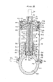
- FIG. 60 an external housing is shown at numeral 60 including a spherical section 62 having heavy walls for resisting very high liquid pressures.
- a very high pressure spherical chamber 64 is enclosed within the walls of section 62.
- Housing 60 also encloses a cylindrical chamber 66 which is closed at one end by means of an end cap member 68 including a boss 70 containing an inlet passage 72 which is adapted to be threadedly engaged with a conduit such as conduit 24 (see Figure 1) connected to the high pressure source.
- Movable within the cylinder 66 is a piston 74 to which is attached a rod 76.
- a spring 78 urges piston 74 toward the end cap member 68.
- Part of the wall of section 62 which is directed toward the inside housing 60 includes a cylindrical opening 80 for receiving and supporting the end of rod 76.
- a portion of the cylindrical passageway 80 is of expanded diameter as shown at numeral 82 and this opening combined with a member 84, which surrounds and partially supports the rod 76, together define an annular groove which receives a seal consisting of a rubber O-ring 85 covered by an annular seal 86 of polytetrafluoroethylene material and a plurality of metal and plastic backup rings 88.
- An additional expanded diameter collar 90 constituting an extension of section 62 which supports the rod 76 is threadedly engaged with a member 92 which, as it is turned into the inside of collar 90, compresses the seal members such that they provide a proper seal between section 62 and the end of the rod 76. This must be an unusally good seal because of the extremely high pressures within chamber 64.
- a small passageway 94 which is normally , Iosed by means of a bleed valve member 96 threadedly engaged with housing 60 and which communicates with another small passageway 98 leading to the interior of cylindrical chamber 66.
- Bleed valve member 96 provides a means of permitting the contents of chamber. 64- to be exhausted through passageways 94 and 98, the interior of cylindrical chamber 66, and out of a port 100 which leads to the return line 22 (see Figure 1).
- piston 74 includes a stepped groove arrangement 102 at its periphery which contains a seal including an 0-ring member 104 and a plurality of metal and plastic backup rings 106.
- a small sealing ring 112 Radially inwardly from the 0-ring 104 is a small sealing ring 112 which senses system pressure tending to drive the 0- ring radially outward.
- This ring 112 is placed adjacent another small ring 116, and each of these rings is adjacent a small annulus 114 which communicates pressure forcing ring 112 outwardly.
- Ring 116 serves to prevent ring 112 from blocking ports (not shown) communicating the annulus 114 with the sealing ring 104.
- An essentially identical sealing arrangement is used in both the end cap 68 and the piston 74.
- the end cap 68 is secured in the housing 60 by means of a shear ring 118 which is secured against a shoulder in the end cap 68 and within a groove in the housing 60 to prevent internal pressure acting on the inside of the end cap 68 from forcing this end cap out of the housing 60.
- a small plate 120 is secured to the end cap 68 by means of a series of bolts 122 which feed through some heavy washers 124 and which are threadedly engaged with the end cap 68. Since end plate 120 extends over the ends of the housing 60, the arrangement described will prevent end cap 68 from moving inwardly as a result of any unusual low pressures in the interior of cylindrical chamber 66 or from external forces.
- a small diameter passageway 126 is drilled through the central axis of piston 74 and rod 76, and this passageway contains a shaft 128 fastened to a check valve member 130.
- this passage is expanded to include a valve seat area 132 which is circular and formed at right angles to the axis of the shaft 128.
- the check valve member.130 has a flat circular face opposing seat 132 and includes a plurality of annular rings 134 which make contact against seat 132.
- a light spring 136 tends to urge check valve member 130 against the seat 132.
- shaft 128 is secured in annular support members 138 and 140 which freely permit the passage of liquid therethrough.
- the liquid spring accumulator of Figure 2 although slightly different in configuration from that described above, operates in almost exactly the same manner. Hydraulic oil supplied under initial pressure to inlet port 72 will pass thr Q ugh a plurality of passages 142 to the adjacent surface of piston 74 and will also flow through the passageway 126 and past check valve member 130 into chamber 64. Check valve 130 is held open because the shaft 128 is in direct contact with the end cap member 68. Further increases in fluid pressure applied to the upper end of piston 74 will cause the piston to move downwardly against the force of spring 78, carrying the shaft 128 away from its contact with end cap 68 and permitting the check valve member 130 to close against seat 132.
- piston 74 and rod 76 will continue to move downwardly, forcing rod 76 into chamber 64 where a comparatively small displacement of the rod will result in rapid increases in the fluid pressure.
- This pressure will increase until a stability is reached wherein the system pressure operating on the area of piston 74 equals the pressure in housing 64 acting on the smaller area of rod 76.
- the resulting liquid pressure in housing 64 will approach a value 10 times that of the system pressure. This pressure is then available in the system to supply energy during peaks of demand as required or to absorb pressure surges.
Landscapes
- Engineering & Computer Science (AREA)
- Physics & Mathematics (AREA)
- Fluid Mechanics (AREA)
- Mechanical Engineering (AREA)
- General Engineering & Computer Science (AREA)
- Supply Devices, Intensifiers, Converters, And Telemotors (AREA)
Abstract
Description
- This invention relates to a liquid spring accumulator with self-charging means.
- A liquid spring accumulator includes a high strength housing having inlet and return ports communicating with a source of liquid under high pressure and incorporating a high pressure chamber and a cylindrical chamber containing a piston communicating on one side with said source of liquid under high pressure and on its other side with the return side of said source and with a resilient member which urges the piston toward said inlet port. A rod of substantially smaller area than said piston and attached thereto communicates with the high pressure chamber such that when said piston is exposed to said high pressure liquid, the piston forces the rod into the volume of liquid in the high pressure chamber to effect a substantial pressure increase in said high pressure chamber.
- Accumulators of various types have been commonly used in pneumatic and hydraulic control actuation systems to suppress pressure surges or to supply energy during peaks of demand when the fluid pressure requirements may be greater than the pressure source can deliver. Probably the greatest number of accumulators in use are pneumatic rather than liquid, and such pneumatic accumulators tend to be somewhat lighter in weight than liquid accumulators. With increasing operating pressures and increased requirements for reliability, it has begun to appear that, as compared with a pneumatic accumulator, a liquid spring accumulator has . several advantages with relatively little sacrifice in weight and space requirements. The primary benefits are related to elimination of the gas charge, i.e., no system degradation because of gas leakage and no service required. As compared with gas or pneumatic-type accumulators, reliability is enhanced because:
- (1) there are no high pressure gas lines that require, continual servicing with special maintenance equipment,
- (2) there is no depletion of the gas charge externally, which requires extra fluid reservoir volume to compensate, and
- (3) there is no depletion of the gas charge internally, which results in low spring rate unstable operation. ,
- Since the regular hydraulic actuating liquid is used in the spring accumulator, any leakage goes directly into the system return chamber at return pressure and so no special fluids are required.
- An additional advantage of the liquid spring accumulator as compared with a gas accumulator is that it is inherently much less vulnerable to battle damage or structural damage because of the thick walls required. Further, if the liquid spring accumulator is damaged severely, the energy entrapped in the high pressure chamber is released with much less potential damage to the surrounding structure.
- Because of the very high liquid pressures created in liquid spring accumulators, special care must be taken with seals to avoid premature failure. In earlier efforts to design such accumulators, applicant succeeded in producing an operative accumulator which developed a liquid spring pressure of approximately 5000 Kg/cm2, but seal failures were experienced after approximately 60 cycles. The seal problems have been successfully surmounted, and the liquid spring accumulator now appears to offer increased reliability with a reduction in overall space requirements. For specific applications these advantages more than offset a possible weight penalty. A self-charging liquid spring accumulator is defined as one which uses system hydraulic fluid compressability as the energy storage spring. Pressure generated for energy storage is achieved by an area stepdown reduction from the system piston to the liquid spring pressure chamber rod; thus, ultra high pressure is developed in this chamber from the feeding of normal system pressure. The self-charging feature is incorporated by means of a check valve which opens when system pressure and return pressure are approximately equal and provides communication between system pressure and the liquid spring fluid chamber to fill the chamber. When system pressure is applied, the first pressure buildup will overcome the system piston return spring; then piston movement will close the check valve. Further pressure buildup transmits load to the closed liquid spring volume through the area ratio of the system piston to the liquid spring rod.
- In the drawings:
- Figure 1 is a schematic diagram of a hydraulic system for controlling a hydraulic servo actuator incorporating a liquid spring accumulator according to the invention,
- Figures la and lb show the accumulator of Figure 1 in different operating positions; and
- Figure 2 is a sectional drawing of another embodiment of the liquid spring accumulator.
- Referring now to the schematic of Figure 1, a
pump 10 of any suitable design is shown supplying hydraulic liquid under pressure through acontrol valve 12 via aline 14 to ahydraulic actuator 16.Actuator 16 consists of a conventional hydraulic cylinder with a piston therein movable to effect movement of a control surface or other member.Control valve 12 also has a connection to the return side of the pump throughconduit 18. In the position of thecontrol valve 12 shown no fluid is supplied to or from theactuator 16 which is therefore locked in position. Were thevalve 12 to be move downwardly, the high pressure would be supplied to the upper end ofhydraulic cylinder 16 and the lower end would be connected to the return line. Myliquid spring accumulator 20 is shown connected throughlines pump 10 respectively. Acontrol valve 26 is shown connected tolines liquid spring accumulator 20 can be depressurized when desired. Valve 26 can be operated either manually or through a solenoid or suitable control means. Theliquid spring accumulator 20 consists of ahousing 28 having heavy walls and including acylindrical chamber 30 containing aspring 32. This spring urges apiston 34 in an upward direction against the force of hydraulic pressure supplied fromline 24 through aninlet port 36 to the upper side ofpiston 34. Attached topiston 34 is arod 38 which extends downwardly through a channel in thehousing 28, thereby communicating with a highfluid pressure chamber 40. A movablecheck valve member 42 is located in an elongatedaxial passage 44 extending through the center ofpiston 34 androd 38.Member 42 includes anelongated shaft 46 which, as shown, makes contact with the upper end ofhousing 28, and because of this contact thevalve member 42 is prevented from seating on its seat inpassage 44. Alight spring 50 urgescheck valve member 42 toward its seat. Thehigh pressure chamber 40 is connected toreturn line 22 through aconduit 52 containing a bleedvalve 54, shown manually operated but which could be operated through other means. Through the use of this bleed valve it is possible between operating cycles for maintenance personnel to directly connectchamber 40 with the return side ofpump 10 thereby effectively removing air from this chamber to assure that it is filled with hydraulic liquid. - In the position shown in Figure 1, high pressure from
pump 10 is connected throughline 24 andinlet port 36 to the upper side ofpiston 34. Sincepiston 34 is in its uppermost position, theshaft 46 attached to checkvalve member 42 is in contact with the end of the chamber andvalve member 42 is held open. This permits high pressure fluid to be communicated throughpassageway 44 to thehigh pressure chamber 40 and permitting this high pressure chamber ,to be filled with fluid. Figure la shows a subsequent position ofpiston 34 which, under pressure, has begun to move in a downward direction. As it does so, it carries thecheck valve member 42 along, and this member now seats under the influence ofspring 50 because therod 46 is no longer in contact with the end of the cylindrical chamber. - The pressure on the upper side of
piston 34 will continue to build up' to system pressure as supplied by the pump which might, for example, be 570 Kg/cm2, and the effect of building to this pressure level is shown in Figure lb wherein it will be seen that thepiston 34 is moved downwardly a substantial distance incylindrical chamber 30 compressingspring 32 and forcing therod 38 deeply into thehigh pressure chamber 40. Since the increase in pressure inchamber 40 acts through the center ofrod 38 to even more firmly seat thecheck valve member 42, the pressure inchamber 40 is trapped and will be increased as its displacement is reduced from further intrusion of therod 38 intochamber 40. Since the hydraulic fluid in this chamber is liquid and only somewhat compressible, the pressure will rise very considerably to a value which is controlled by the relative area ratios between the area ofpiston 34 and that ofrod 38. In one accumulator with which applicant has been working, the maximum pressure in the high pressure chamber reached 5700 Kg/cm2 with 570 Kg/cm2 incylinder 30. From the foregoing it is believed that the reader will understand the operation of my liquid spring accumulator as installed in a hydraulic circuit for an actuator or similar control device. Thevalve 26 shown connected inline 24 leading to theaccumulator 20 is not always necessary but provides a means for reducing pressure in the accumulator when desired. - Structural details of my liquid spring accumulator will become somewhat more clearly defined from examination of the sectional drawing, Figure 2. In this drawing an external housing is shown at
numeral 60 including aspherical section 62 having heavy walls for resisting very high liquid pressures. A very high pressurespherical chamber 64 is enclosed within the walls ofsection 62.Housing 60 also encloses a cylindrical chamber 66 which is closed at one end by means of anend cap member 68 including aboss 70 containing aninlet passage 72 which is adapted to be threadedly engaged with a conduit such as conduit 24 (see Figure 1) connected to the high pressure source. Movable within the cylinder 66 is apiston 74 to which is attached arod 76. Aspring 78urges piston 74 toward theend cap member 68. Part of the wall ofsection 62 which is directed toward theinside housing 60 includes acylindrical opening 80 for receiving and supporting the end ofrod 76. A portion of thecylindrical passageway 80 is of expanded diameter as shown atnumeral 82 and this opening combined with amember 84, which surrounds and partially supports therod 76, together define an annular groove which receives a seal consisting of a rubber O-ring 85 covered by anannular seal 86 of polytetrafluoroethylene material and a plurality of metal andplastic backup rings 88. An additional expandeddiameter collar 90 constituting an extension ofsection 62 which supports therod 76 is threadedly engaged with amember 92 which, as it is turned into the inside ofcollar 90, compresses the seal members such that they provide a proper seal betweensection 62 and the end of therod 76. This must be an unusally good seal because of the extremely high pressures withinchamber 64. - Communicating with
chamber 64 is asmall passageway 94 which is normally , Iosed by means of ableed valve member 96 threadedly engaged withhousing 60 and which communicates with anothersmall passageway 98 leading to the interior of cylindrical chamber 66. Bleedvalve member 96 provides a means of permitting the contents of chamber. 64- to be exhausted throughpassageways port 100 which leads to the return line 22 (see Figure 1). - It will be observed that
piston 74 includes a steppedgroove arrangement 102 at its periphery which contains a seal including an 0-ring member 104 and a plurality of metal and plastic backup rings 106. Radially inwardly from the 0-ring 104 is asmall sealing ring 112 which senses system pressure tending to drive the 0- ring radially outward. Thisring 112 is placed adjacent anothersmall ring 116, and each of these rings is adjacent asmall annulus 114 which communicatespressure forcing ring 112 outwardly.Ring 116 serves to preventring 112 from blocking ports (not shown) communicating theannulus 114 with the sealingring 104. An essentially identical sealing arrangement is used in both theend cap 68 and thepiston 74. Theend cap 68 is secured in thehousing 60 by means of ashear ring 118 which is secured against a shoulder in theend cap 68 and within a groove in thehousing 60 to prevent internal pressure acting on the inside of theend cap 68 from forcing this end cap out of thehousing 60. - A
small plate 120 is secured to theend cap 68 by means of a series ofbolts 122 which feed through someheavy washers 124 and which are threadedly engaged with theend cap 68. Sinceend plate 120 extends over the ends of thehousing 60, the arrangement described will preventend cap 68 from moving inwardly as a result of any unusual low pressures in the interior of cylindrical chamber 66 or from external forces. - A
small diameter passageway 126 is drilled through the central axis ofpiston 74 androd 76, and this passageway contains ashaft 128 fastened to acheck valve member 130. At the inside end ofpassageway 126 nearest thehigh pressure chamber 64 this passage is expanded to include avalve seat area 132 which is circular and formed at right angles to the axis of theshaft 128. The check valve member.130 has a flat circularface opposing seat 132 and includes a plurality ofannular rings 134 which make contact againstseat 132. Alight spring 136 tends to urgecheck valve member 130 against theseat 132. To assure proper alignment of thecheck valve member 130 with theseat 132,shaft 128 is secured inannular support members - The liquid spring accumulator of Figure 2, although slightly different in configuration from that described above, operates in almost exactly the same manner. Hydraulic oil supplied under initial pressure to
inlet port 72 will pass thrQugh a plurality of passages 142 to the adjacent surface ofpiston 74 and will also flow through thepassageway 126 and pastcheck valve member 130 intochamber 64.Check valve 130 is held open because theshaft 128 is in direct contact with theend cap member 68. Further increases in fluid pressure applied to the upper end ofpiston 74 will cause the piston to move downwardly against the force ofspring 78, carrying theshaft 128 away from its contact withend cap 68 and permitting thecheck valve member 130 to close againstseat 132. With a further buildup of pressure,piston 74 androd 76 will continue to move downwardly, forcingrod 76 intochamber 64 where a comparatively small displacement of the rod will result in rapid increases in the fluid pressure. This pressure will increase until a stability is reached wherein the system pressure operating on the area ofpiston 74 equals the pressure inhousing 64 acting on the smaller area ofrod 76. With an area ratio between the piston and the rod of approximately 10 to 1, the resulting liquid pressure inhousing 64 will approach avalue 10 times that of the system pressure. This pressure is then available in the system to supply energy during peaks of demand as required or to absorb pressure surges. - When the hydraulic system is shut down, it is considered desirable to remove the pressure from the high pressure chamber. This can be done automatically by reducing system pressure to return pressure and allowing
spring 78 to drive thepiston 74 to the right and to forceopen check valve 132 or through operation of thebleed valve 96 which can be manually turned to provide communication betweenpassages chamber 64 to be exhausted through theconduits return port 100 and returnpressure line 22. It is considered advantageous to remove the pressure from the accumulator at the end of each duty cycle and refill and repressurize at the beginning of the next cycle, primarily because some leakage is practically inevitable with the pressures encountered, and retaining the accumulator in a pressurized condition between cycles will result in initiating subsequent cycles with lower pressures because of such leakage.
Claims (5)
characterized in that said accumulator includes an axial passage (126) through said piston (74) and rod (76) connecting said inlet port (72) with said high pressure chamber (64), a check valve (130) in said passage, means (128) holding said check valve open when said piston (74) is nearest said inlet port (72), and a spring (136) urging said check valve (130) toward a closing direction, such that when said operating liquid is first supplied to said housing (60), said check valve (130) permits said high pressure chamber (64) to be filled, and when said operating liquid pressure reaches a predetermined level above the pressure on the return side of said source, said piston (74) initially moves to cause said check valve (130) to be closed and further increases in said operating liquid pressure acting against said piston (74) forces said piston to carry said rod (76) into said high pressure chamber (64).
Applications Claiming Priority (2)
| Application Number | Priority Date | Filing Date | Title |
|---|---|---|---|
| US06/357,968 US4450870A (en) | 1982-03-15 | 1982-03-15 | Liquid spring accumulator with self-charging means |
| US357968 | 1982-03-15 |
Publications (3)
| Publication Number | Publication Date |
|---|---|
| EP0089286A2 true EP0089286A2 (en) | 1983-09-21 |
| EP0089286A3 EP0089286A3 (en) | 1984-08-29 |
| EP0089286B1 EP0089286B1 (en) | 1987-05-06 |
Family
ID=23407767
Family Applications (1)
| Application Number | Title | Priority Date | Filing Date |
|---|---|---|---|
| EP83400509A Expired EP0089286B1 (en) | 1982-03-15 | 1983-03-11 | Liquid spring accumulator with self-charging means |
Country Status (4)
| Country | Link |
|---|---|
| US (1) | US4450870A (en) |
| EP (1) | EP0089286B1 (en) |
| JP (1) | JPS58166101A (en) |
| DE (1) | DE3371397D1 (en) |
Cited By (1)
| Publication number | Priority date | Publication date | Assignee | Title |
|---|---|---|---|---|
| FR2555696A1 (en) * | 1983-11-30 | 1985-05-31 | Kubota Ltd | TRANSMISSION APPARATUS FOR AGRICULTURE VEHICLE COMPRISING A DEVICE FOR CHANGING PROGRESSIVE OIL SPEED |
Families Citing this family (7)
| Publication number | Priority date | Publication date | Assignee | Title |
|---|---|---|---|---|
| DE10350941A1 (en) * | 2003-10-31 | 2005-06-02 | Hydac Technology Gmbh | Device for damping pressure surges |
| US9212670B2 (en) * | 2012-02-08 | 2015-12-15 | Gm Global Technology Operations, Llc | Composite accumulator |
| US9739292B1 (en) | 2014-03-21 | 2017-08-22 | Kocsis Technologies, Inc. | Hydraulic accumulator having a closing arrangement |
| US9992910B2 (en) * | 2015-06-11 | 2018-06-05 | Cooler Master Co., Ltd. | Liquid supply mechanism and liquid cooling system |
| US10954966B2 (en) * | 2017-10-25 | 2021-03-23 | Raytheon Company | Bootstrap accumulator containing integrated bypass valve |
| CN113217482B (en) * | 2021-04-09 | 2022-03-11 | 燕山大学 | A piston accumulator with built-in check valve |
| US20240263649A1 (en) * | 2021-05-13 | 2024-08-08 | Advanced Energy Storage, Llc | Accumulator with reinforcing structure |
Family Cites Families (9)
| Publication number | Priority date | Publication date | Assignee | Title |
|---|---|---|---|---|
| US2546055A (en) * | 1944-09-02 | 1951-03-20 | Charles U Ballard | Compensator |
| US2780504A (en) * | 1954-04-21 | 1957-02-05 | Parker Appliance Co | Accumulator piston |
| US2943642A (en) * | 1958-07-07 | 1960-07-05 | Cleveland Pneumatic Ind Inc | Liquid spring accumulator |
| US3348579A (en) * | 1965-03-26 | 1967-10-24 | Int Harvester Co | Self-adjusting pulsating fluid pressure damping accumulator |
| US3473328A (en) * | 1967-11-01 | 1969-10-21 | Jergens Tool Specialty Co | Pressure multiplying booster |
| FR2133497B1 (en) * | 1971-04-15 | 1974-03-08 | Claret Lucien | |
| FR2154274B1 (en) * | 1971-08-19 | 1977-01-21 | Westinghouse Freins & Signaux | |
| US3907001A (en) * | 1973-02-12 | 1975-09-23 | Pneumo Dynamics Corp | Combination accumulator reservoir |
| GB2100347A (en) * | 1981-06-15 | 1982-12-22 | Phillips Bruce Howard | Hydraulic booster assembly |
-
1982
- 1982-03-15 US US06/357,968 patent/US4450870A/en not_active Expired - Lifetime
-
1983
- 1983-03-11 EP EP83400509A patent/EP0089286B1/en not_active Expired
- 1983-03-11 DE DE8383400509T patent/DE3371397D1/en not_active Expired
- 1983-03-15 JP JP58041642A patent/JPS58166101A/en active Pending
Cited By (1)
| Publication number | Priority date | Publication date | Assignee | Title |
|---|---|---|---|---|
| FR2555696A1 (en) * | 1983-11-30 | 1985-05-31 | Kubota Ltd | TRANSMISSION APPARATUS FOR AGRICULTURE VEHICLE COMPRISING A DEVICE FOR CHANGING PROGRESSIVE OIL SPEED |
Also Published As
| Publication number | Publication date |
|---|---|
| DE3371397D1 (en) | 1987-06-11 |
| EP0089286A3 (en) | 1984-08-29 |
| US4450870A (en) | 1984-05-29 |
| EP0089286B1 (en) | 1987-05-06 |
| JPS58166101A (en) | 1983-10-01 |
Similar Documents
| Publication | Publication Date | Title |
|---|---|---|
| US4776952A (en) | Regulated control valve assembly for a water purification system | |
| US4777800A (en) | Static head charged hydraulic accumulator | |
| US4368008A (en) | Reciprocating controls of a gas compressor using free floating hydraulically driven piston | |
| US4527580A (en) | Volume control device | |
| US4210170A (en) | Anti-cavitation and overload relief valve for a hydraulic system | |
| JPH02102901A (en) | Method and device for filling hydropneumatic intensifying type pressure transducer with pressure oil | |
| JPS6113079B2 (en) | ||
| US5377488A (en) | Hydro-pneumatic pressure transformer | |
| US6866066B2 (en) | Hydraulic accumulator | |
| US4450870A (en) | Liquid spring accumulator with self-charging means | |
| US4375181A (en) | Hydraulic cylinder extending in three force modes | |
| US20080078455A1 (en) | Compact Manifolded Fail Safe Hydraulic Control System | |
| EP1226333B1 (en) | A device in a subsea system for controlling a hydraulic actuator and a subsea system with a hydraulic actuator | |
| US2731038A (en) | Hydraulic accumulator | |
| US4291718A (en) | Pressure valve | |
| KR860001697B1 (en) | Actuator with pneumatic energy accumulator | |
| US4383804A (en) | Lubrication and sealing of a free floating piston of hydraulically driven gas compressor | |
| US5927178A (en) | Press driven tool actuator module | |
| GB2092717A (en) | Hydraulic control valve assembly | |
| US12270397B2 (en) | Pump configuration including a purge valve for removing airlocks | |
| CN213332683U (en) | Control valve with hydraulic electric drive | |
| GB2043210A (en) | Controlled pressure-release valve | |
| RU2739221C1 (en) | Hydraulic drive protection system | |
| SU1015074A1 (en) | Rope and cable sealing-away system | |
| RU2018755C1 (en) | Safety valve |
Legal Events
| Date | Code | Title | Description |
|---|---|---|---|
| PUAI | Public reference made under article 153(3) epc to a published international application that has entered the european phase |
Free format text: ORIGINAL CODE: 0009012 |
|
| 17P | Request for examination filed |
Effective date: 19830322 |
|
| AK | Designated contracting states |
Designated state(s): DE FR GB |
|
| PUAL | Search report despatched |
Free format text: ORIGINAL CODE: 0009013 |
|
| AK | Designated contracting states |
Designated state(s): DE FR GB |
|
| 17Q | First examination report despatched |
Effective date: 19860127 |
|
| RAP1 | Party data changed (applicant data changed or rights of an application transferred) |
Owner name: ALLIED CORPORATION |
|
| GRAA | (expected) grant |
Free format text: ORIGINAL CODE: 0009210 |
|
| AK | Designated contracting states |
Kind code of ref document: B1 Designated state(s): DE FR GB |
|
| REF | Corresponds to: |
Ref document number: 3371397 Country of ref document: DE Date of ref document: 19870611 |
|
| ET | Fr: translation filed | ||
| PLBE | No opposition filed within time limit |
Free format text: ORIGINAL CODE: 0009261 |
|
| STAA | Information on the status of an ep patent application or granted ep patent |
Free format text: STATUS: NO OPPOSITION FILED WITHIN TIME LIMIT |
|
| 26N | No opposition filed | ||
| PGFP | Annual fee paid to national office [announced via postgrant information from national office to epo] |
Ref country code: GB Payment date: 19910304 Year of fee payment: 9 |
|
| PGFP | Annual fee paid to national office [announced via postgrant information from national office to epo] |
Ref country code: FR Payment date: 19910320 Year of fee payment: 9 |
|
| PGFP | Annual fee paid to national office [announced via postgrant information from national office to epo] |
Ref country code: DE Payment date: 19910402 Year of fee payment: 9 |
|
| PG25 | Lapsed in a contracting state [announced via postgrant information from national office to epo] |
Ref country code: GB Effective date: 19920311 |
|
| GBPC | Gb: european patent ceased through non-payment of renewal fee | ||
| PG25 | Lapsed in a contracting state [announced via postgrant information from national office to epo] |
Ref country code: FR Effective date: 19921130 |
|
| PG25 | Lapsed in a contracting state [announced via postgrant information from national office to epo] |
Ref country code: DE Effective date: 19921201 |
|
| REG | Reference to a national code |
Ref country code: FR Ref legal event code: ST |