EP0089142B1 - Fallschirm - Google Patents
Fallschirm Download PDFInfo
- Publication number
- EP0089142B1 EP0089142B1 EP83301112A EP83301112A EP0089142B1 EP 0089142 B1 EP0089142 B1 EP 0089142B1 EP 83301112 A EP83301112 A EP 83301112A EP 83301112 A EP83301112 A EP 83301112A EP 0089142 B1 EP0089142 B1 EP 0089142B1
- Authority
- EP
- European Patent Office
- Prior art keywords
- canopy
- parachute
- constituted
- lines
- apex
- Prior art date
- Legal status (The legal status is an assumption and is not a legal conclusion. Google has not performed a legal analysis and makes no representation as to the accuracy of the status listed.)
- Expired
Links
- 239000000725 suspension Substances 0.000 claims description 34
- 238000005192 partition Methods 0.000 claims description 29
- 230000015572 biosynthetic process Effects 0.000 claims description 10
- 238000005755 formation reaction Methods 0.000 claims description 10
- 239000004744 fabric Substances 0.000 claims description 9
- 230000002093 peripheral effect Effects 0.000 claims description 4
- 241000826860 Trapezium Species 0.000 claims description 3
- 230000005484 gravity Effects 0.000 claims description 3
- 230000007423 decrease Effects 0.000 claims description 2
- 238000010276 construction Methods 0.000 description 1
- 230000001419 dependent effect Effects 0.000 description 1
- 230000000694 effects Effects 0.000 description 1
- 238000004519 manufacturing process Methods 0.000 description 1
- 238000005259 measurement Methods 0.000 description 1
- 230000002028 premature Effects 0.000 description 1
- 230000003019 stabilising effect Effects 0.000 description 1
- 230000003068 static effect Effects 0.000 description 1
Images


Classifications
-
- B—PERFORMING OPERATIONS; TRANSPORTING
- B64—AIRCRAFT; AVIATION; COSMONAUTICS
- B64D—EQUIPMENT FOR FITTING IN OR TO AIRCRAFT; FLIGHT SUITS; PARACHUTES; ARRANGEMENT OR MOUNTING OF POWER PLANTS OR PROPULSION TRANSMISSIONS IN AIRCRAFT
- B64D17/00—Parachutes
- B64D17/22—Load suspension
- B64D17/24—Rigging lines
-
- B—PERFORMING OPERATIONS; TRANSPORTING
- B64—AIRCRAFT; AVIATION; COSMONAUTICS
- B64D—EQUIPMENT FOR FITTING IN OR TO AIRCRAFT; FLIGHT SUITS; PARACHUTES; ARRANGEMENT OR MOUNTING OF POWER PLANTS OR PROPULSION TRANSMISSIONS IN AIRCRAFT
- B64D17/00—Parachutes
- B64D17/62—Deployment
Definitions
- This invention relates to parachutes and more particularly but not exclusively to parachutes for military application.
- a parachute conventionally comprises a canopy defining a periphery, a plurality of suspension lines secured at upper ends thereof to the periphery of the canopy and having at the lower ends thereof a connecting arrangement whereby a load, such as a parachutist, may be connected to the parachute.
- parachute troops In military operations it is often preferred to drop parachute troops from a relatively low altitude.
- the minimum altitude from which troops can safely be dropped depends inter alia on the opening time of the parachute, that is the time it takes for the parachute to convert from streamer configuration to fully inflated configuration.
- streamer configuration is used in this specification to denote the initial stage of the deployment of a parachute immediately after the apex of the canopy has been separated from the static line. At this stage only minimal inflation of the canopy has taken place and it has a tubular shape which during inflation converts to a dome shape.
- the opening time of a parachute is dependent on various design features. This invention relates to two such features.
- skirt spreading forces While in its streamer configuration there is set up in the canopy certain forces which are generally referred to as skirt spreading forces. These forces result inter alia from the entrapment of air in the tubular canopy and from the flow of air over the outer surface of the canopy. It has now been realised that the gravitational force acting on the load and transmitted through the suspension lines to canopy tends to counteract the skirt spreading forces. The present invention is concerned with a means to minimise such counteraction of the skirt spreading forces.
- a parachute includes a canopy defining a periphery, a connecting arrangement adapted for use in connecting the parachute to a load, a main suspension system. comprising a plurality of lines spaced about the periphery of the canopy and secured to the canopy to extend between the peripheral zone of the canopy and the connecting arrangement, and an auxiliary suspension system comprising upper and lower line arrangements, each of which is disposed adjacent to a line substantially on the axis of the canopy while the canopy is in streamer configuration, and load transfer means radially disposed within the canopy and having opposed ends, one of said ends being secured to the upper and lower line arrangements, and the other end of the load transfer means being secured to the interior of the canopy, the arrangement of the two suspension systems being such that, in use, the opposing forces of drag action on the canopy and gravity acting on the load are substantially taken up by the auxiliary suspension system, leaving the main suspension system essentially untensioned, while the canopy is in streamer configuration, and by the main suspension system when the canopy is fully deployed.
- the canopy is of substantially circular planform and may for example be of a flat, conical, parabolic or hemispherical profile.
- the canopy may be of a conventional construction constituted by a plurality of substantially triangular gores joined along main seams.
- the gores in turn may be constituted by a plurality of panels (normally four) joined along cross seams and each gore panel may be of isosceles trapezium or trapezoid shape, that is, a trapezium or trapezoid resulting from the truncation of an isosceles triangle.
- the auxiliary suspension system may include a fabric partition sewn at its ends to diametrically opposing main seams of the canopy, and a pair of lower axial lines extending from a central position on a lower edge of the partition to the connecting arrangement.
- the auxiliary suspension system includes four partitions which in the deployed form of the canopy divide the canopy into four quadrants, the partitions being joined together along a line which falls substantially on the axis of the canopy when in use and the lower axial lines extending between the joint between the partitions and the connecting arrangement.
- the height of the fabric partition is selected to extend between the periphery of the canopy and the uppermost cross seam on the gores joined by the main seam to which the partition is sewn.
- the height of the partition also preferably decreases progressively from its ends connected to the canopy to its central region so as to define an obtuse angle at the central zone of the lower edges of the partition, i.e. at the position where the lower axial lines are connected.
- the auxiliary suspension system may further include an upper axial line extending between a central position on or towards the upper edge of the partition and the apex of the canopy, the length of the upper axial line being such that it is only tensioned while the parachute is in streamer configuration.
- the auxiliary suspension system comprises a plurality of internal radial lines joined at first ends thereof to the interior surface of the canopy at a position intermediate the periphery and the apex thereof and joined together at their opposite ends in a confluence, an upper axial line extending between the confluence and the apex of the canopy and a lower axial line arrangement extending between the load connecting arrangement and the confluence.
- the internal radial lines are preferably connected to the canopy surface at points of intersection between main seams and cross seams. These points are hereinafter referred to as fastening points.
- the lower axial line arrangement preferably comprises two lower axial lines and the load connecting arrangement also preferably comprises two spaced connector links, each lower axial line extending between the confluence and one of the connectors.
- AD+DB+BC is between 97.5% and 99.5% of (AE+EC) and (AB+BC) is between 98.5% and 99.9% of (AD+DB+BC).
- a parachute having a canopy of dome shaped deployed configuration and including a vent at the apex thereof is characterised in that it includes pocket formations disposed on the interior surface of the canopy in the vent region thereof, the pocket formations being arranged and adapted in use to inflate thereby to occlude the vent while the canopy is in streamer configuration and to be disposed clear of the vent when the parachute is fully deployed.
- At least four pockets are provided and located collectively to extend about the vent.
- Each pocket may be constituted by a quadrilateral flap formation of which the upper edge and two side edges are sewn to the canopy to define with the canopy fabric a downwardly open pocket formation.
- the flap formations may be of generally truncated triangular configuration to constitute, in association with the canopy fabric covered by the flaps, pockets of generally conical shape.
- the upper edge of the flaps may further be of arcuate configuration to fit neatly about a segment of the circumference of the vent.
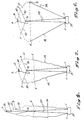
- a parachute 10 comprises a canopy 11, having a vent 12 in the apex region 13 thereof and suspension lines 14 (of which only two are shown) extending from the peripheral zone of the canopy and secured to the load 15 via connector links (not shown).
- a partition 16 (shown in dotted lines) having a central seam 16a is disposed in the canopy and sewn to two diametrically opposed main seams. It will be seen (Figure 3) that the upper edge 17 of the partition 16 defines a straight line and the lower edge 18 defines an obtuse angle 19 in the centre thereof.
- the partition 16 For ease of reference only one partition is shown which divides the canopy into two segments. It is however preferred to have the canopy divided in quadrants by means of two intersecting partitions.
- An upper axial line 20 is secured to the apex lines 21 and to the centre 22 of the upper edge 17 of the partition 16.
- Two substantially axial lines 23 extend between a connecting point at the apex of the angle 19 and the connecting links (not shown) by which the load 15 is connected to the parachute 10.
- the fabric partition shown in Figure 3 is replaced by a number of internal radial lines 30.
- the internal radial lines 30 are secured to fastening points D which fall on the intersections of cross seams and main seams (not illustrated) of the canopy 11.
- 5 and 6 only two internal radial lines 30 are shown but it is preferred to have eight internal radial lines extending between the canopy 11 and a confluence B.
- An upper axial line 20 extends between the centre A of the vent 12 and the confluence B. It will be understood that the upper end of the upper axial line is connected to the apex lines spanning the vent 12.
- the auxiliary suspension system of the parachute further includes two lower axial lines 23 which extend between the confluence B and the connecting links C secured to the load 15.
- the suspension lines 14 are in tensioned state while the parachute is in streamer configuration. It will be seen that the tensioned state of the main suspension lines tends to gather the periphery of the canopy to a "closed" configuration and thus opposes the skirt spreading forces and consequently reduces the opening speed of the canopy.
- auxiliary suspension system axial lines 23 and radial lines 30
- the partition 16 and the internal radial lines 30 can be indicated generally as 'load transfer means'.
- a parachute comprises a canopy 11 defining a vent 12 in its centre and a peripheral zone 3 to which suspension lines (not shown) are secured.
- quadrilateral flaps 4 of generally truncated triangular shape are sewn to the canopy 11 along three edges thereof as shown by the dotted lines 5 in Figure 7.
- the radially extending stitches are preferably located along main seams (not shown) of the canopy.
- the upper edges of the flaps 4 are shown to be curved to fit neatly along the curvature of the vent 12. As the lower edges 4b are not sewn to the canopy, the flaps constitute downwardly open pocket formations as can best be seen from Figure 8.
- the dotted lines show the pockets 4 in limp or collapsed condition.
- the pockets or flaps 4 will normally be in this condition while no air passes through the tubular configuration defined by the canopy while it is in streamer configuration. However, once air enters the canopy the flaps are scooped and caused to billow to assume roughly a position as shown in solid lines at 4 in Figure 8. It will be seen that in billowed condition the flaps 4 occlude the vent 12 which in turn speeds up the deployment of the parachute since entrapped air is not permitted to escape through the vent 12.
Landscapes
- Engineering & Computer Science (AREA)
- Aviation & Aerospace Engineering (AREA)
- Toys (AREA)
- Air Bags (AREA)
Claims (12)
Applications Claiming Priority (4)
| Application Number | Priority Date | Filing Date | Title |
|---|---|---|---|
| ZA821548 | 1982-03-09 | ||
| ZA821547 | 1982-03-09 | ||
| ZA821547 | 1982-03-09 | ||
| ZA821548 | 1982-03-09 |
Publications (2)
| Publication Number | Publication Date |
|---|---|
| EP0089142A1 EP0089142A1 (de) | 1983-09-21 |
| EP0089142B1 true EP0089142B1 (de) | 1987-05-20 |
Family
ID=27133544
Family Applications (1)
| Application Number | Title | Priority Date | Filing Date |
|---|---|---|---|
| EP83301112A Expired EP0089142B1 (de) | 1982-03-09 | 1983-03-02 | Fallschirm |
Country Status (5)
| Country | Link |
|---|---|
| US (1) | US4488694A (de) |
| EP (1) | EP0089142B1 (de) |
| CA (1) | CA1231694A (de) |
| DE (1) | DE3371622D1 (de) |
| IL (1) | IL68069A (de) |
Families Citing this family (3)
| Publication number | Priority date | Publication date | Assignee | Title |
|---|---|---|---|---|
| US5248117A (en) * | 1992-04-08 | 1993-09-28 | The United States Of America As Represented By The Secretary Of The Navy | Regulated drag area parachute |
| GB2322606B (en) * | 1997-03-01 | 2001-04-11 | Wardle Storeys Ltd | Parachutes |
| US8096509B2 (en) * | 2008-08-07 | 2012-01-17 | Fox Jr Roy L | Parachute inlet control system and method |
Family Cites Families (11)
| Publication number | Priority date | Publication date | Assignee | Title |
|---|---|---|---|---|
| DE364408C (de) * | 1918-02-21 | 1922-11-24 | Ballonhuellen Ges M B H | In einem Behaelter untergebrachter, nach unten herausziehbarer Fallschirm |
| US1777934A (en) * | 1928-11-21 | 1930-10-07 | Owens Frank Roderick | Parachute |
| US2103806A (en) * | 1936-11-03 | 1937-12-28 | Mark S Willing | Parachute |
| US2127895A (en) * | 1936-11-11 | 1938-08-23 | William E Tingle | Parachute |
| US2371898A (en) * | 1939-10-12 | 1945-03-20 | Lisl Giuseppe | Parachute with variable surface |
| US2350480A (en) * | 1942-01-12 | 1944-06-06 | Tina Brooker Fite | Parachute |
| FR896186A (fr) * | 1942-04-23 | 1945-02-14 | A R Co Anonima Romana Costruzi | Dispositif de réglage de la vitesse de chute d'un parachute annulaire |
| US2575387A (en) * | 1951-01-29 | 1951-11-20 | Kluglein Helmuth | Parachute |
| FR1192116A (fr) * | 1955-02-16 | 1959-10-23 | Voilure de parachute à dispositifs éjecteur et extracteur incorporés | |
| US3131894A (en) * | 1963-01-10 | 1964-05-05 | Domina C Jalbert | Multi-cell glide canopy parachute |
| US3773284A (en) * | 1972-02-25 | 1973-11-20 | Us Army | Controllable multi-stage increasing drag parachute |
-
1983
- 1983-03-02 EP EP83301112A patent/EP0089142B1/de not_active Expired
- 1983-03-02 DE DE8383301112T patent/DE3371622D1/de not_active Expired
- 1983-03-03 US US06/471,679 patent/US4488694A/en not_active Expired - Fee Related
- 1983-03-07 IL IL68069A patent/IL68069A/xx unknown
- 1983-03-08 CA CA000423091A patent/CA1231694A/en not_active Expired
Also Published As
| Publication number | Publication date |
|---|---|
| EP0089142A1 (de) | 1983-09-21 |
| CA1231694A (en) | 1988-01-19 |
| DE3371622D1 (en) | 1987-06-25 |
| US4488694A (en) | 1984-12-18 |
| IL68069A (en) | 1990-08-31 |
Similar Documents
| Publication | Publication Date | Title |
|---|---|---|
| US5388787A (en) | Air impermeable parachute canopy with opening assist | |
| AU723277B2 (en) | Device to control inflation characteristics of parachutes | |
| EP1317374B1 (de) | Kreuzfallschirm mit verbundenen kreuzschenkeln | |
| EP0900163B1 (de) | Kreuzförmiges fallschirmsystem | |
| US6164594A (en) | Device for braking the fall of a load | |
| AU2001285134A1 (en) | Cruciform parachute with arms attached | |
| AU2001285134A2 (en) | Cruciform parachute with arms attached | |
| EP0089142B1 (de) | Fallschirm | |
| US6003815A (en) | Parachutes | |
| US2683575A (en) | Vented sector parachute | |
| US5738307A (en) | Parachute with slidable auxiliary canopy for opening assist | |
| US5209436A (en) | Radial reefing means for use in packing and opening a parachute canopy in a controlled manner | |
| US4270714A (en) | Parachute canopy | |
| US3452951A (en) | High drag efficiency parachute canopy | |
| JP2743171B2 (ja) | パラシユートの天蓋 | |
| US20070152102A1 (en) | High drag parachute with radial slots providing porosity distribution and enhanced stability without forward speed | |
| US2774561A (en) | Load-retarding canopy of preformed type | |
| EP0015778B1 (de) | Hilfsvorrichtung zum Entfalten eines Fallschirms | |
| US3727863A (en) | Air-venting parachute | |
| US2696959A (en) | Parachute canopy structure | |
| US20260015089A1 (en) | Parachute slider reefing systems and methods |
Legal Events
| Date | Code | Title | Description |
|---|---|---|---|
| PUAI | Public reference made under article 153(3) epc to a published international application that has entered the european phase |
Free format text: ORIGINAL CODE: 0009012 |
|
| AK | Designated contracting states |
Designated state(s): DE FR GB IT |
|
| 17P | Request for examination filed |
Effective date: 19840107 |
|
| RAP1 | Party data changed (applicant data changed or rights of an application transferred) |
Owner name: DEMLUX SECURITIES B.V. |
|
| ITF | It: translation for a ep patent filed | ||
| GRAA | (expected) grant |
Free format text: ORIGINAL CODE: 0009210 |
|
| AK | Designated contracting states |
Kind code of ref document: B1 Designated state(s): DE FR GB IT |
|
| REF | Corresponds to: |
Ref document number: 3371622 Country of ref document: DE Date of ref document: 19870625 |
|
| ET | Fr: translation filed | ||
| PLBE | No opposition filed within time limit |
Free format text: ORIGINAL CODE: 0009261 |
|
| STAA | Information on the status of an ep patent application or granted ep patent |
Free format text: STATUS: NO OPPOSITION FILED WITHIN TIME LIMIT |
|
| 26N | No opposition filed | ||
| PGFP | Annual fee paid to national office [announced via postgrant information from national office to epo] |
Ref country code: GB Payment date: 19900228 Year of fee payment: 8 |
|
| PGFP | Annual fee paid to national office [announced via postgrant information from national office to epo] |
Ref country code: FR Payment date: 19900322 Year of fee payment: 8 |
|
| PGFP | Annual fee paid to national office [announced via postgrant information from national office to epo] |
Ref country code: DE Payment date: 19900330 Year of fee payment: 8 |
|
| PG25 | Lapsed in a contracting state [announced via postgrant information from national office to epo] |
Ref country code: GB Effective date: 19910302 |
|
| GBPC | Gb: european patent ceased through non-payment of renewal fee | ||
| PG25 | Lapsed in a contracting state [announced via postgrant information from national office to epo] |
Ref country code: FR Effective date: 19911129 |
|
| PG25 | Lapsed in a contracting state [announced via postgrant information from national office to epo] |
Ref country code: DE Effective date: 19920101 |
|
| REG | Reference to a national code |
Ref country code: FR Ref legal event code: ST |