EP0089109A1 - Mixing apparatus - Google Patents
Mixing apparatus Download PDFInfo
- Publication number
- EP0089109A1 EP0089109A1 EP83300558A EP83300558A EP0089109A1 EP 0089109 A1 EP0089109 A1 EP 0089109A1 EP 83300558 A EP83300558 A EP 83300558A EP 83300558 A EP83300558 A EP 83300558A EP 0089109 A1 EP0089109 A1 EP 0089109A1
- Authority
- EP
- European Patent Office
- Prior art keywords
- rotor
- passages
- inlet
- axis
- inlets
- Prior art date
- Legal status (The legal status is an assumption and is not a legal conclusion. Google has not performed a legal analysis and makes no representation as to the accuracy of the status listed.)
- Withdrawn
Links
Images


Classifications
-
- F—MECHANICAL ENGINEERING; LIGHTING; HEATING; WEAPONS; BLASTING
- F23—COMBUSTION APPARATUS; COMBUSTION PROCESSES
- F23K—FEEDING FUEL TO COMBUSTION APPARATUS
- F23K5/00—Feeding or distributing other fuel to combustion apparatus
- F23K5/02—Liquid fuel
- F23K5/08—Preparation of fuel
- F23K5/10—Mixing with other fluids
- F23K5/12—Preparing emulsions
-
- B—PERFORMING OPERATIONS; TRANSPORTING
- B01—PHYSICAL OR CHEMICAL PROCESSES OR APPARATUS IN GENERAL
- B01F—MIXING, e.g. DISSOLVING, EMULSIFYING OR DISPERSING
- B01F25/00—Flow mixers; Mixers for falling materials, e.g. solid particles
- B01F25/60—Pump mixers, i.e. mixing within a pump
- B01F25/64—Pump mixers, i.e. mixing within a pump of the centrifugal-pump type, i.e. turbo-mixers
Definitions
- the present invention is concerned with apparatus for mixing two liquids particularly immiscible liquids and especially for introducing water into fuel supplies, especially hydrophobic fuels., in such a manner as to improve the combustion characteristics of the fuel mixture.
- fuel supplies especially hydrophobic fuels.
- it is also effective in mixing light and heavy fuels such as alcohols and petroleum fuels, such as diesel fuels or higher distillates.
- the apparatus for ease of reference, will be referred to as an emulsifier.
- the emulsifier has been developed with the particular problems of industrial oil-fired boilers in mind, but is also applicable to the supply of fuel to diesel engines, to gas turbines and to fuel injection, or carburettor petrol engines.
- the present invention is concerned with an improvement over the emulsifier shown in our earlier Patent No. 1572698.
- apparatus for mixing fluids comprises a housing affording a substantially annular mixing chamber, an annular rotor mounted for rotation in the mixing chamber, outwardly extending individual passages being located in the rotor, the inlets to the passages in the rotor being disposed at or adjacent its axis of rotation, the passages in the rotor extending rearwardly from the said inlets to the periphery of the rotor and emerging therethrough.
- the invention may include any one or more of the following features in any combination.
- the median line for each passage may make a rearward angle with the radius of the rotor at the passage inlet, which is in the range up to 35° e.g. 1° to 30° or 5 to 30 0 or 20 to 25°.
- An inlet chamber disposed at or adjacent the axis of rotation of the rotor may communicate with the inlets in the rotor.
- the inlet chamber may be provided with inlet means for the fluids to be mixed.
- the mixing chamber may have a circular outer wall extending preferably around a major proportion of its circumference preferably with a clearance between the said circular wall and the periphery of the rotor, the circular outer wall extending outwardly preferably into a spiral shape so as to define a preferably generally crescent shaped outlet region between the preferably spiral shaped wall of the mixing chamber and the periphery of the rotor, the outlet region communicating with an outlet passage.
- the individual passages extending out through the peripheral.surface of the rotor may be spaced from each other by solid regions of the peripheral surface, the ratio of the radial distance from the inlet to each passage to the outer surface of the rotor to the radius of the rotor preferably being in the range of 0.4:1 to 0.9:1.
- the ratio of the radius of the rotor to the clearance between the periphery of the rotor and the circular portion, pf the outer wall of the mixing chamber is preferably at least 200:1.
- the radial passages preferably have at least one constriction intermediate their ends. In one preferred form of the invention, 4 to 20 radial passages are provided. In one form of the invention each radial passage preferably has a convergent entry portion leading to the constriction and a divergent outlet portion.
- the passages may each comprise a V-shaped convergent inlet portion.and a V-shaped divergent outlet portion defining a constriction between them, the constriction optionally being a parallel sided throat portion interconnecting the V-shaped inlet end and the V-shaped outlet end of each passage.
- the V-shaped inlet end preferably forms an included angle of 40 to 80° and the V-shaped outlet end preferably forms an included angle of 10 to 40 0 .
- each passage is preferably 0.6 times the radius of the rotor.
- the passages may be open at one face of the rotor which is closely spaced from a wall of the missing chamber, or the passages may be closed along their length.
- the rotor may be generally conical to enable the area of the inlet to a passage to be about equal to the area of the outlet.
- the invention also extends to the rotor per se.
- reference 100 denotes the fuel injection system of the engine, 101 being the inlet line thereto and 102 being the outlet therefrom to the high spill return line 103.
- the inlet 101 to the injector 100 is fed by a line 104 and main fuel pump 105.
- the main fuel pump 105 draws in the fuel and water emulsion via a line 107 from an emulsifier 106 of appropriate type such as that described below with reference to Figures 2 to 5.
- the emulsifier is fed with fuel from a fuel tank 110 having a filter 111 in its outlet by a lift pump 112 via a further filter 113 and a line 114.
- the emulsifier is fed with water from a water supply 120 via a filter 121 and a line 122.
- the water supply may be a header tank, an accumulator driven by the engine e.g. by its water pump,or may be a constant displacement pump. The first two options are preferred.
- the spill return line passes through a cooler 130 e.g. provided with forced cooling by a cooling water inlet 131 - and outlet 132.
- the cooled spill return then passes via a line 133 to the smoothing means which are shown as a tank 140 having a vent 141 to atmosphere.
- the smoothed spill return then passes by the line 142 to the emulsifier 106.
- the emulsifier shown in Figures 2 to 5 consists of an inlet chamber housing 10 and a seal housing 11 appropriately secured together in leak-proof fashion.
- the housings 10 and 11 between them provide a mixing chamber 15 and a seal chamber 35.
- Located in the mixing chamber 15 for free rotation therein is a rotor 20 having radial passages 19, the rotor being supported on a drive shaft 21 which extends out through a mechanical seal 23 and the seal housing 11 to an external drive motor 24.
- the seal 23 is located within the seal chamber 35 formed between the seal housing 11 and inlet chamber housing 10.
- the seal chamber 35 is separated from'the mixing chamber 15 by the rotor 20 except for a small clearance, C, between the outer edge of the rotor and the inner peripheral wall 37 of the mixing chamber 15. Liquids may be prevented from passing directly through into the chamber 35 by the provision of a recirculation flow of the emulsion which is introduced through an orifice (not shown) into the seal housing 11 and which provides a cooling effect for the seal and then recombines with the emulsion in the chamber 15.
- the housing 10 provides an inlet chamber 50 which is fed by three inlet passages, a water inlet passage 51, a fuel inlet passage 52 and a spill return passage (not shown). Each supply line 114, 122, and 142 to these.passages is preferably provided with an on-off valve (hot shown) adjacent the emulsifier.
- the inlet chamber comprises the rounded sided disc shaped chamber 53 at the confluence of the passages 51 and 52, plus a cylindrical chamber 49 located between the central end face 54 of the rotor 20, a wall 55 into which the inner ends of the passages 19 open and a face 56 of the chamber 53.
- the mixing chamber 15 is defined as being bounded by a front wall 60, an inner wall 61 extending from the inside edge of the front wall parallel to the longitudinal axis of the device, an inclined wall 62 joining the inner wall 61 to an outer side wall, of which part, 37, is cylindrical and part, 66, is on a spiral, and a plane 64 extending across the axis of the housing 10 parallel to the front wall 60 from the rear wall 63 of the part 66 of the side wall.
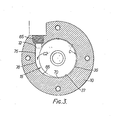
- the mixing chamber communicates with an outlet passage 65 disposed tangentially to the rotor (see also Figure 3) and transverse to its axis.
- the circular wall extends around the chamber for 240° and the spiral wall 66 extends outwardly from the point 70 to the outer edge of the outlet passage 65.
- the mixing chamber includes this part crescent shaped region extending from point 70 to the line 72 across the opening 65.
- the mixing chamber is largely occupied by the rotor 20.
- the clearance, C, between the wall 37 and the outer space of the rotor is preferably at least 0.001" e.g. 0.001" to 0.070", e.g. 0.020 to 0.060 and especially 0.045 to 0.055 inches (1.1 to 1.4 mms):
- the generally crescent shaped region may have a flat outer wall 66 as shown in Figure 3. However, one convenient way of making this part of the housing is to mill out the cylindrical mixing chamber and drill the circular outlet opening 65 tangentially to the circular chamber down to the point 78.
- the wall 66 need not be flat.
- the maximum clearance, C2, between the wall 66 and the periphery of the rotor at the point 78 is many times that of the clearance C between the wall 37 and the rotor and the ratio C2/C is preferably at least'10:1 and more desirably at least 50:1 or 100:1 and particularly in the range 50:1 to 200:1 or 500:1.
- the rotor has a base 80 secured to or formed on a rotor shaft 81 sleeved at 82 to suit the drive shaft of the motor 24, and having a clearance hole 83 for the end fixing of the drive shaft which may be a bolt 85 and washer 86 (see Figure 2).
- the rotor also has a generally conically shaped top portion 87 in which eight outwardly extending passages 19 are formed e.g. by milling or casting.
- the top 87 is secured to the base 80 by four equispaced screws 88 (see Figure 5) passing through holes in the base 88 into tappings in the top 87.
- the base 80 and the portions 77 are integrally formed and the portion indicated by 87 and cross hatched in Figure 4 is screwed to the base by the screws 88.
- the periphery of the rotor once the top and base have been secured is given deep knurling 90 as illustrated diagrammatically in Figure 5 for one vane 77.
- the knurling is preferably a criss- cross pattern of two arrays of parallel grooves inclined at 45° to each other each groove having a maximum depth of 0.010 inches (0.25 mms) and a maximum width of 0.015 inches (0.38 mms) and adjacent parallel grooves being at least 0.020 inches (0.51 mms) apart.
- the depths of the grooves can vary from 0.01 preferably 0.1 to 0.25 mm, and the widths of the grooves from 0.02 to 0.4 mms e.g. 0.2 to 0.35 mms and the separation of adjacent parallel grooves can vary from 0.5 to 2 mms, e.g. 0.5 to 1 mm.
- the rotor has a diameter 3 D1,where the diameter of the circle 150 (which defines the wall 55
- the V-shaped inlet region 172 has a radial length (IRL) of about 0.09 Dl, the outlet region has a radial length (ORL) of about 0.9 D1, whilst its length (OML) along the median line 152 of the passage (see Figure 5) is about 1.05 D1.
- the median line 152 of the passage is constructed by joining the mid points of the chords 153 and 154 drawn across the inlet (which Ls on the circle 150 which defines the inlet wall 55) and the outlet to the passage respectively.
- the angle (AM) between the median line and the radius through the point A, the mid point of the chord 153, is preferably from 15°-20° to 25°-30°, especially about 22.5°.
- the rotor also has an inlet collar 155 at its input end, the radial extent of which is about 3 D1/20.
- the ducts or passages 19 are inclined backwardly in the sense of the direction of rotation of the rotor (arrow 157 in Figure 5).
- the passages are thus as ymme- trical and produce a very slight pumping action in addition to their cavitation function. Aslight pressure head will thus be developed between the inlet and outlet of the device in use.
- the ducts 19 are also converged in the direction of the rotational axis of the rotor on passing from the inlet wall 55 to the outlet wall 36.
- the angle AA of this convergence is about 15°; more broadly it may be in the range 10° to 20°.
- the rotor is arranged so that the ratio of IAL to OAL lies in the range 0.2:1 to 0.8:1 e.g. 0.3:1 to 0.7:1 especially 0.4:1 to 0.6:1.
- the ratio of the length of the passages 19 as measured along the median line 152 to the diameter of the rotor is preferably in the range 0.6:1 to 1.35:1 e.g. 0.75:1 to 1.2:1 or especially 0.96:1 to 1.11:1.
- the axial convergence is designed to ensure that the flow area at the inlet to each passage 19 is closely the same and preferably virtually the same as the flow area at the outlet to each passage at the circumference to the rotor.
- the ratio of inlet flow area IFA to the outlet flow area.OFA is desirably in the range 0.8:1 to 1.2:1 and especially in the range 0.9:1 to 1.1:1 and particularly in the range 0.95:1 to 1.05:1.
- the dimension A is preferably related to the diameter D1 of the rotoreye, the circle 150 on which the rotor inlets lie, by the equation:
- the rotor 20 in this embodiment has eight outwardly extending passages 19 equally spaced apart through 45° and extending from the inlet wall 55 (defined by the circle 150) to the outer periphery 36 of the rotor 20.
- each passage is a V-shaped slot 172 including an angle, AI, of 65° and the outlet end is a V-shaped slot 73 including an angle, AO, of about 25°.
- the two V-shaped slots interact to form a constriction which is located on the circle.156.
- the rotor In operation the rotor is rotated in the direction shown by the arrow 157 in Figure 5 i.e. with the passages facing out backwards with regard to the direction of rotation.
- the liquids to be mixed are drawn from the inlet chamber by the centrifugal force on the liquid in the passages 19 and thrown out radially through the passages 19 and caused to hit the wall 37.
- the outer wall 36 of the rotor is broken up into eight solid portions 77, each of about the same circumferential length as the outlets 73, and the solid portions 77 may be considered to act as vanes, and as mentioned above they preferably have knurled surfaces 90.
- the constriction 71 has the function of impeding the flow of fluid along the passage 19 and thus increasing its velocity outwardly and the diverging outlet slot 73 then causes a pressure drop in the fluid resulting in vapourisation of the fuel in the mixture.
- the rotor shown is very suitable for fuels having viscosities from 35 Redwood seconds up to 3000 Redwood seconds with rotor speeds of 2800 to 7000 r.p.m.
- the rotor is thought to work by vaporisation of the fuel as it goes through the throat of the passages 19 producing cavitation in the fuel/water mixture, the water droplets are thought to be sheared by the wall 37 and the vanes 77, and the fuel is thought to condense on the surface of the.water droplets in the turbulent flow region 78 producing droplets having micron particle size and thus promoting smooth and more complete combustion.
- the rotor has a base 80 similar to that of Figure 4.
- the rotor has a generally conically shaped top edge 160, eight open-topped outwardly-extending.passages 19 being formed in the base 80 and opening out along the edge 160.
- the top wall 160 is juxtaposed to the inclined wall 62 of the housihg 10 so as to be substantially parallel thereto and the clearance between 160 and 62 is substantially smaller than that between 36 and 37 ( Figure 3) for example preferably being less than 0.020 inches (0.50 mms) and especially less.than 0.015 inches (0.38 mms) e.g. in the range 0.005.to 0.015 inches (0.12 to 0.38 mms) and particularly about 0.010 inches (0.25 mms).
- the periphery of the rotor is given deep knurling 90 as illustrated diagrammatically in Figure 5.
- constriction 71 is not present, the inclined passages 19 having the same width in the plane of Figure 5 along their whole length, but apart from that being as described for Figures 4 and 5.
- the axial convergence shown in Figure 4 is eliminated or is also eliminated so that the passages 19 are either of the same axial length along their whole radial length but have the constriction 71 and are inclined backwards or the passages 19 are of the same axial length (see Figure 4) and are of the same width in the plane of Figure 5 along their whole length but are inclined backwards as shown and described for Figure 5.
Abstract
Apparatus for mixing fluids comprises a housing (10) affording a substantially annular mixing chamber (15), and an annular rotor (20) mounted for rotation in the mixing chamber, outwardly extending individual passages (19) being located in the rotor, the inlets to the passages in the rotor being disposed (55) adjacent its axis of rotation, the passages in the rotor leading from the said inlets to the periphery of the rotor (36) and emerging therethrough, the median line (152) through each passage in a plane perpendicular to the axis of the rotor intersecting the circle around the axis of the rotor on which the inlet to the said passages lies at a point A and making a rearward angle with the radius of the rotor which passes through the said point A for that passage. An inlet chamber (49, 53) communicates with the inlets in the rotor adjacent the axis of rotation of the rotor, the inlet chamber being provided with inlet means for the fluids to be mixed. The mixing chamber has a circular outer wall (37) extending around a major proportion of its circumference with a small clearance with the periphery of the rotor.
Description
- The present invention is concerned with apparatus for mixing two liquids particularly immiscible liquids and especially for introducing water into fuel supplies, especially hydrophobic fuels., in such a manner as to improve the combustion characteristics of the fuel mixture. However it is also effective in mixing light and heavy fuels such as alcohols and petroleum fuels, such as diesel fuels or higher distillates.
- The apparatus, for ease of reference, will be referred to as an emulsifier. The emulsifier has been developed with the particular problems of industrial oil-fired boilers in mind, but is also applicable to the supply of fuel to diesel engines, to gas turbines and to fuel injection, or carburettor petrol engines.
- Our earlier British Patent No. 1572698 discloses an emulsifier by which,by mechanical means alone, without the need for surfactants, emulsions of water and oil can be produced.
- Investigations since the filing of that application have revealed that it produces micron size water droplets each carrying a coating of the oil with which the water has been mixed.
- Subsequent work has corroborated that the device is effective in mixing water and a wide range of hydrocarbon fuels and it will be appreciated that blends with alcohols such as methanol or ethanol can also be emulsified.
- The present invention is concerned with an improvement over the emulsifier shown in our earlier Patent No. 1572698.
- According to the present invention apparatus for mixing fluids comprises a housing affording a substantially annular mixing chamber, an annular rotor mounted for rotation in the mixing chamber, outwardly extending individual passages being located in the rotor, the inlets to the passages in the rotor being disposed at or adjacent its axis of rotation, the passages in the rotor extending rearwardly from the said inlets to the periphery of the rotor and emerging therethrough.
- The invention may include any one or more of the following features in any combination. The median line for each passage may make a rearward angle with the radius of the rotor at the passage inlet, which is in the range up to 35° e.g. 1° to 30° or 5 to 300 or 20 to 25°. An inlet chamber disposed at or adjacent the axis of rotation of the rotor may communicate with the inlets in the rotor. The inlet chamber may be provided with inlet means for the fluids to be mixed. The mixing chamber may have a circular outer wall extending preferably around a major proportion of its circumference preferably with a clearance between the said circular wall and the periphery of the rotor, the circular outer wall extending outwardly preferably into a spiral shape so as to define a preferably generally crescent shaped outlet region between the preferably spiral shaped wall of the mixing chamber and the periphery of the rotor, the outlet region communicating with an outlet passage.
- The individual passages extending out through the peripheral.surface of the rotor may be spaced from each other by solid regions of the peripheral surface, the ratio of the radial distance from the inlet to each passage to the outer surface of the rotor to the radius of the rotor preferably being in the range of 0.4:1 to 0.9:1.
- The ratio of the radius of the rotor to the clearance between the periphery of the rotor and the circular portion, pf the outer wall of the mixing chamber is preferably at least 200:1.
- The radial passages preferably have at least one constriction intermediate their ends. In one preferred form of the invention, 4 to 20 radial passages are provided. In one form of the invention each radial passage preferably has a convergent entry portion leading to the constriction and a divergent outlet portion.
- The passages may each comprise a V-shaped convergent inlet portion.and a V-shaped divergent outlet portion defining a constriction between them, the constriction optionally being a parallel sided throat portion interconnecting the V-shaped inlet end and the V-shaped outlet end of each passage.
- The V-shaped inlet end preferably forms an included angle of 40 to 80° and the V-shaped outlet end preferably forms an included angle of 10 to 40 0 .
- The radial length of each passage is preferably 0.6 times the radius of the rotor.
- The passages may be open at one face of the rotor which is closely spaced from a wall of the missing chamber, or the passages may be closed along their length.
- The rotor may be generally conical to enable the area of the inlet to a passage to be about equal to the area of the outlet. The invention also extends to the rotor per se.
- The invention may be put into practice in various ways and two specific embodimentswill be described to illustrate the invention with reference to the accompanying drawings in which:
- Figure 1 is a flow diagram of a fuel supply system appropriate for use with a high spill return fuel injection engine;
- Figure 2 is a longitudinal cross-section of a preferred embodiment of an emulsifier in accordance with the present invention;
- Figure 3 is a cross-section on the line III-III of Figure 2, on a reduced scale, showing the mixing chamber and, diagrammatically, the outline of the-rotor;
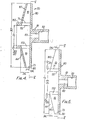
- Figures 4 and 6 are cross-sections on the line IV-IV of Figure 5, on an enlarged scale showing in detail the shape of the passages in two fornsof the rotor; and
- Figure 5 is a cross-section of Figures 4 and 6 on the line V-V.
- Referring now to Figure 1
reference 100 denotes the fuel injection system of the engine, 101 being the inlet line thereto and 102 being the outlet therefrom to the highspill return line 103. - The
inlet 101 to theinjector 100 is fed by aline 104 andmain fuel pump 105. Themain fuel pump 105 draws in the fuel and water emulsion via aline 107 from anemulsifier 106 of appropriate type such as that described below with reference to Figures 2 to 5. - The emulsifier is fed with fuel from a
fuel tank 110 having afilter 111 in its outlet by alift pump 112 via afurther filter 113 and aline 114. - The emulsifier is fed with water from a
water supply 120 via afilter 121 and aline 122. The water supply may be a header tank, an accumulator driven by the engine e.g. by its water pump,or may be a constant displacement pump. The first two options are preferred. - The spill return line passes through a cooler 130 e.g. provided with forced cooling by a
cooling water inlet 131-andoutlet 132. The cooled spill return then passes via aline 133 to the smoothing means which are shown as atank 140 having avent 141 to atmosphere. The smoothed spill return then passes by theline 142 to theemulsifier 106. - The structure of a preferred form of emulsifier in accordance with the invention will now be described.
- The emulsifier shown in Figures 2 to 5 consists of an
inlet chamber housing 10 and a seal housing 11 appropriately secured together in leak-proof fashion.. Thehousings 10 and 11 between them provide amixing chamber 15 and aseal chamber 35. Located in themixing chamber 15 for free rotation therein is arotor 20 havingradial passages 19, the rotor being supported on adrive shaft 21 which extends out through amechanical seal 23 and the seal housing 11 to anexternal drive motor 24. - The
seal 23 is located within theseal chamber 35 formed between the seal housing 11 andinlet chamber housing 10. Theseal chamber 35 is separated from'themixing chamber 15 by therotor 20 except for a small clearance, C, between the outer edge of the rotor and the innerperipheral wall 37 of themixing chamber 15. Liquids may be prevented from passing directly through into thechamber 35 by the provision of a recirculation flow of the emulsion which is introduced through an orifice (not shown) into the seal housing 11 and which provides a cooling effect for the seal and then recombines with the emulsion in thechamber 15. Thehousing 10 provides aninlet chamber 50 which is fed by three inlet passages, awater inlet passage 51, afuel inlet passage 52 and a spill return passage (not shown). Eachsupply line - The inlet chamber comprises the rounded sided disc shaped chamber 53 at the confluence of the
passages cylindrical chamber 49 located between thecentral end face 54 of therotor 20, awall 55 into which the inner ends of thepassages 19 open and aface 56 of the chamber 53. - The
mixing chamber 15 is defined as being bounded by afront wall 60, aninner wall 61 extending from the inside edge of the front wall parallel to the longitudinal axis of the device, aninclined wall 62 joining theinner wall 61 to an outer side wall, of which part, 37, is cylindrical and part, 66, is on a spiral, and aplane 64 extending across the axis of thehousing 10 parallel to thefront wall 60 from therear wall 63 of thepart 66 of the side wall. The mixing chamber communicates with anoutlet passage 65 disposed tangentially to the rotor (see also Figure 3) and transverse to its axis. - The circular wall extends around the chamber for 240° and the
spiral wall 66 extends outwardly from thepoint 70 to the outer edge of theoutlet passage 65. The mixing chamber includes this part crescent shaped region extending frompoint 70 to the line 72 across the opening 65. The mixing chamber is largely occupied by therotor 20. - The clearance, C, between the
wall 37 and the outer space of the rotor is preferably at least 0.001" e.g. 0.001" to 0.070", e.g. 0.020 to 0.060 and especially 0.045 to 0.055 inches (1.1 to 1.4 mms): The generally crescent shaped region may have a flatouter wall 66 as shown in Figure 3. However, one convenient way of making this part of the housing is to mill out the cylindrical mixing chamber and drill the circular outlet opening 65 tangentially to the circular chamber down to thepoint 78. One can then pick out theregion 15 with a milling machine from a line 72 down to thepoint 70 so as to smooth out the transition between thehole 65 and thecircular wall 37 of the mixing chamber to form the curved region extending from the line 72 to thepoint 70. In this arrangement, thewall 66 need not be flat. The maximum clearance, C2, between thewall 66 and the periphery of the rotor at thepoint 78 is many times that of the clearance C between thewall 37 and the rotor and the ratio C2/C is preferably at least'10:1 and more desirably at least 50:1 or 100:1 and particularly in the range 50:1 to 200:1 or 500:1. - Referring now to Figures 4 and 5 which show the
rotor 20, the rotor has abase 80 secured to or formed on arotor shaft 81 sleeved at 82 to suit the drive shaft of themotor 24, and having aclearance hole 83 for the end fixing of the drive shaft which may be abolt 85 and washer 86 (see Figure 2). The rotor also has a generally conically shapedtop portion 87 in which eight outwardly extendingpassages 19 are formed e.g. by milling or casting. Thetop 87 is secured to thebase 80 by four equispaced screws 88 (see Figure 5) passing through holes in thebase 88 into tappings in thetop 87. In an alternative-arrangement thebase 80 and theportions 77 are integrally formed and the portion indicated by 87 and cross hatched in Figure 4 is screwed to the base by thescrews 88. The periphery of the rotor once the top and base have been secured is givendeep knurling 90 as illustrated diagrammatically in Figure 5 for onevane 77. The knurling is preferably a criss- cross pattern of two arrays of parallel grooves inclined at 45° to each other each groove having a maximum depth of 0.010 inches (0.25 mms) and a maximum width of 0.015 inches (0.38 mms) and adjacent parallel grooves being at least 0.020 inches (0.51 mms) apart. More broadly the depths of the grooves can vary from 0.01 preferably 0.1 to 0.25 mm, and the widths of the grooves from 0.02 to 0.4 mms e.g. 0.2 to 0.35 mms and the separation of adjacent parallel grooves can vary from 0.5 to 2 mms, e.g. 0.5 to 1 mm. - The rotor has a
diameter 3 D1,where the diameter of the circle 150 (which defines thewall 55 - . on which the inlets to the
passages 19 lie) is D1. Thepassages 19 each have an inlet axial length (IAL) of A and an outlet axial length (OAL) of about 0.5 A where A = 3/8 (D1). The V-shapedinlet region 172 has a radial length (IRL) of about 0.09 Dl, the outlet region has a radial length (ORL) of about 0.9 D1, whilst its length (OML) along themedian line 152 of the passage (see Figure 5) is about 1.05 D1. - The
median line 152 of the passage is constructed by joining the mid points of thechords circle 150 which defines the inlet wall 55) and the outlet to the passage respectively. - The angle (AM) between the median line and the radius through the point A, the mid point of the
chord 153, is preferably from 15°-20° to 25°-30°, especially about 22.5°. - The rotor also has an
inlet collar 155 at its input end, the radial extent of which is about 3 D1/20. - The ducts or
passages 19 are inclined backwardly in the sense of the direction of rotation of the rotor (arrow 157 in Figure 5). The passages are thus as ymme- trical and produce a very slight pumping action in addition to their cavitation function. Aslight pressure head will thus be developed between the inlet and outlet of the device in use. - The
ducts 19 are also converged in the direction of the rotational axis of the rotor on passing from theinlet wall 55 to theoutlet wall 36. The angle AA of this convergence is about 15°; more broadly it may be in therange 10° to 20°. Preferably the rotor is arranged so that the ratio of IAL to OAL lies in the range 0.2:1 to 0.8:1 e.g. 0.3:1 to 0.7:1 especially 0.4:1 to 0.6:1. - The ratio of the length of the
passages 19 as measured along themedian line 152 to the diameter of the rotor is preferably in the range 0.6:1 to 1.35:1 e.g. 0.75:1 to 1.2:1 or especially 0.96:1 to 1.11:1. - The axial convergence is designed to ensure that the flow area at the inlet to each
passage 19 is closely the same and preferably virtually the same as the flow area at the outlet to each passage at the circumference to the rotor. Thus the ratio of inlet flow area IFA to the outlet flow area.OFA is desirably in the range 0.8:1 to 1.2:1 and especially in the range 0.9:1 to 1.1:1 and particularly in the range 0.95:1 to 1.05:1. - The dimension A is preferably related to the diameter D1 of the rotoreye, the
circle 150 on which the rotor inlets lie, by the equation:
- With a rotor in which D1 = 1.5 inches (3.8 cms) the device can deliver a flow, F, of up to 300 gallons (Imperial)/hour of emulsion with a power requirement (PR) of 1.5 H.P. for the motor; when Dl = 2 inches (5.1 cms), F = up to 450 and PR = 2.5; and when D1 = 3 inches (7.6 cms), F = up to 600 and PR = 3.0.
- Referring now to Figure 5, the
rotor 20 in this embodiment has eight outwardly extendingpassages 19 equally spaced apart through 45° and extending from the inlet wall 55 (defined by the circle 150) to theouter periphery 36 of therotor 20. - In this form of the invention the inlet end of each passage is a V-shaped
slot 172 including an angle, AI, of 65° and the outlet end is a V-shapedslot 73 including an angle, AO, of about 25°. The two V-shaped slots interact to form a constriction which is located on the circle.156. - In operation the rotor is rotated in the direction shown by the
arrow 157 in Figure 5 i.e. with the passages facing out backwards with regard to the direction of rotation. The liquids to be mixed are drawn from the inlet chamber by the centrifugal force on the liquid in thepassages 19 and thrown out radially through thepassages 19 and caused to hit thewall 37. Theouter wall 36 of the rotor is broken up into eightsolid portions 77, each of about the same circumferential length as theoutlets 73, and thesolid portions 77 may be considered to act as vanes, and as mentioned above they preferably have knurled surfaces 90. - They thus have the function both of shearing the fuel and water mixture in the gap between the
wall 37 and thewall 36 and propelling it around the circumference of the mixing chamber through the part crescent shapedregion 78, where turbulent mixing may be expected to occur and is preferably encouraged by leaving the last 30° of theoutlet wall 66 unsmoothed and in the rough condition produced by the milling operation, and then ejecting it through theoutlet passage 65. - The
constriction 71 has the function of impeding the flow of fluid along thepassage 19 and thus increasing its velocity outwardly and the divergingoutlet slot 73 then causes a pressure drop in the fluid resulting in vapourisation of the fuel in the mixture. - The rotor shown is very suitable for fuels having viscosities from 35 Redwood seconds up to 3000 Redwood seconds with rotor speeds of 2800 to 7000 r.p.m. The rotor is thought to work by vaporisation of the fuel as it goes through the throat of the
passages 19 producing cavitation in the fuel/water mixture, the water droplets are thought to be sheared by thewall 37 and thevanes 77, and the fuel is thought to condense on the surface of the.water droplets in theturbulent flow region 78 producing droplets having micron particle size and thus promoting smooth and more complete combustion. - Referring now to the rotor shown in Figure 6, to which Figure 5 also applies, the rotor has a base 80 similar to that of Figure 4. The rotor has a generally conically shaped
top edge 160, eight open-topped outwardly-extending.passages 19 being formed in thebase 80 and opening out along theedge 160. Thetop wall 160 is juxtaposed to theinclined wall 62 of thehousihg 10 so as to be substantially parallel thereto and the clearance between 160 and 62 is substantially smaller than that between 36 and 37 (Figure 3) for example preferably being less than 0.020 inches (0.50 mms) and especially less.than 0.015 inches (0.38 mms) e.g. in the range 0.005.to 0.015 inches (0.12 to 0.38 mms) and particularly about 0.010 inches (0.25 mms). The periphery of the rotor is givendeep knurling 90 as illustrated diagrammatically in Figure 5. - In other respects the combustion is similar to that of Figures 4 and 5. The cavitation and pumping action described for that embodiment, occur because of the close proximity of the
top edge 160 of the rotor to thewall 62, (Figure 2). - In one less desired embodiment (not illustrated) the
constriction 71 is not present, theinclined passages 19 having the same width in the plane of Figure 5 along their whole length, but apart from that being as described for Figures 4 and 5. - In two other simpler embodiments (also not illustrated) the axial convergence shown in Figure 4 is eliminated or is also eliminated so that the
passages 19 are either of the same axial length along their whole radial length but have theconstriction 71 and are inclined backwards or thepassages 19 are of the same axial length (see Figure 4) and are of the same width in the plane of Figure 5 along their whole length but are inclined backwards as shown and described for Figure 5.
Claims (10)
1. Apparatus for mixing.fluids comprising a housing affording a substantially annular mixing chamber, an annular rotor mounted for rotation in the mixing chamber, outwardly extending individual passages being located in the rotor, the inlets to the passages in the rotor being near the axis of rotation, the passages in the rotor extending with a backward component from the said inlets to outlets at the periphery of the rotor and emerging therethrough.
2. Apparatus as claimed in Claim 1 in which the median line through each passage in a plane perpendicular to the axis of the rotor makes an angle with the radius of the rotor at the centre of the passage inlet which is in the range 5° to 30° or 20 to 25°.
3. Apparatus as claimed in Claim 1 or Claim 2 including an inlet chamber communicating with the inlets in the rotor and disposed at the axis of rotation of the rotor, the inlet chamber being provided with inlet means for the fluids to be mixed.
4. Apparatus as claimed in any preceding claim in which the mixing chamber has a circular outer wall extending around a major proportion of its circumference with a small clearance between the said circular wall and the periphery of the rotor.
5. Apparatus as claimed in any preceding claim in which the individual passages extend out through the peripheral surface of the rotor and are spaced. from each other by solid regions of the peripheral surface, preferably with roughened surfaces at the periphery.
6. Apparatus as claimed in any preceding claim in which the radial passages have at least one constriction intermediate their ends.
7. Apparatus as claimed in Claim 6 in which the passages each comprise a V-shaped convergent inlet portion and a V-shaped divergent outlet portion and thus define a constriction between them, the constriction optionally being a parallel sided throat portion interconnecting the V-shaped inlet end and the V-shaped outlet end of each passage.
8. Apparatus as claimed in any preceding claim in which the rotor is of generally conical form whereby the individual passages have inlets with a cross-sectional area approximately equal to that of their outlets.
9. Apparatus as claimed.in any preceding claim in which at least one of the rotor faces which are generally perpendicular to the ratio axis is discontinuous so that the passages are open at that face, and that face is closely spaced from the opposed surface of the mixing chamber.
10. A rotor for mixing apparatus as claimed in any preceding claim.
Applications Claiming Priority (4)
| Application Number | Priority Date | Filing Date | Title |
|---|---|---|---|
| GB8203172 | 1982-02-04 | ||
| GB8203173 | 1982-02-04 | ||
| GB8203172 | 1982-02-04 | ||
| GB8203173 | 1982-02-04 |
Publications (1)
| Publication Number | Publication Date |
|---|---|
| EP0089109A1 true EP0089109A1 (en) | 1983-09-21 |
Family
ID=26281891
Family Applications (1)
| Application Number | Title | Priority Date | Filing Date |
|---|---|---|---|
| EP83300558A Withdrawn EP0089109A1 (en) | 1982-02-04 | 1983-02-03 | Mixing apparatus |
Country Status (4)
| Country | Link |
|---|---|
| EP (1) | EP0089109A1 (en) |
| CA (1) | CA1213269A (en) |
| ES (1) | ES8402512A1 (en) |
| WO (1) | WO1983002733A1 (en) |
Cited By (1)
| Publication number | Priority date | Publication date | Assignee | Title |
|---|---|---|---|---|
| US6916366B2 (en) | 2001-04-17 | 2005-07-12 | Jacques Vionnet | Aqueous composition for rendering a substrate hydrophobic |
Families Citing this family (2)
| Publication number | Priority date | Publication date | Assignee | Title |
|---|---|---|---|---|
| EP0982543A1 (en) * | 1998-08-26 | 2000-03-01 | Abb Research Ltd. | Fuel - water emulsifying in gas turbines |
| US7186018B2 (en) * | 2003-05-07 | 2007-03-06 | Ashland Licensing And Intellectual Property Llc | Fuel processing device having magnetic coupling and method of operating thereof |
Citations (7)
| Publication number | Priority date | Publication date | Assignee | Title |
|---|---|---|---|---|
| DE703282C (en) * | 1939-03-10 | 1941-03-05 | Bader & Halbig | Mixing top |
| DE897997C (en) * | 1941-06-24 | 1953-11-26 | Ernst A Itterlein Fa | Rotary agitator |
| US3606270A (en) * | 1970-05-14 | 1971-09-20 | Ludish Co | Continuous power blender |
| FR2167688A1 (en) * | 1972-01-05 | 1973-08-24 | Hege Advanced Systems Corp | High energy rotary mixer - with recycle of one constituent to mix with other in rotor |
| AU459032B2 (en) * | 1969-05-07 | 1975-02-26 | William Hooper Robert | Dynamic mixer and centrifuge combination |
| US4066382A (en) * | 1976-06-18 | 1978-01-03 | General Signal Corporation | Surface aeration impeller |
| GB1572698A (en) * | 1975-12-12 | 1980-07-30 | Dynatrol Consultants Ltd | Mixing apparatus |
-
1983
- 1983-02-03 EP EP83300558A patent/EP0089109A1/en not_active Withdrawn
- 1983-02-03 WO PCT/GB1983/000029 patent/WO1983002733A1/en unknown
- 1983-02-03 CA CA000420805A patent/CA1213269A/en not_active Expired
- 1983-02-04 ES ES519524A patent/ES8402512A1/en not_active Expired
Patent Citations (7)
| Publication number | Priority date | Publication date | Assignee | Title |
|---|---|---|---|---|
| DE703282C (en) * | 1939-03-10 | 1941-03-05 | Bader & Halbig | Mixing top |
| DE897997C (en) * | 1941-06-24 | 1953-11-26 | Ernst A Itterlein Fa | Rotary agitator |
| AU459032B2 (en) * | 1969-05-07 | 1975-02-26 | William Hooper Robert | Dynamic mixer and centrifuge combination |
| US3606270A (en) * | 1970-05-14 | 1971-09-20 | Ludish Co | Continuous power blender |
| FR2167688A1 (en) * | 1972-01-05 | 1973-08-24 | Hege Advanced Systems Corp | High energy rotary mixer - with recycle of one constituent to mix with other in rotor |
| GB1572698A (en) * | 1975-12-12 | 1980-07-30 | Dynatrol Consultants Ltd | Mixing apparatus |
| US4066382A (en) * | 1976-06-18 | 1978-01-03 | General Signal Corporation | Surface aeration impeller |
Cited By (1)
| Publication number | Priority date | Publication date | Assignee | Title |
|---|---|---|---|---|
| US6916366B2 (en) | 2001-04-17 | 2005-07-12 | Jacques Vionnet | Aqueous composition for rendering a substrate hydrophobic |
Also Published As
| Publication number | Publication date |
|---|---|
| ES519524A0 (en) | 1984-02-01 |
| WO1983002733A1 (en) | 1983-08-18 |
| CA1213269A (en) | 1986-10-28 |
| ES8402512A1 (en) | 1984-02-01 |
Similar Documents
| Publication | Publication Date | Title |
|---|---|---|
| US4172668A (en) | Mixing apparatus | |
| DE4137179C2 (en) | Device for producing a water-in-oil emulsion and use of the device on a diesel engine | |
| CA1106835A (en) | Method and apparatus for the continuous production of a slurry explosive containing an emulsified liquid component | |
| JP4005479B2 (en) | Homogenizer | |
| AU694409B2 (en) | Mechanical oil/water emulsifier | |
| GB2109457A (en) | Fuel and water emulsion supply system for diesel engines | |
| US4412512A (en) | Fuel supply system | |
| US4421413A (en) | Apparatus for continuously emulsifying the liquids | |
| JPS6214330B2 (en) | ||
| EP0089109A1 (en) | Mixing apparatus | |
| JP2556254Y2 (en) | Pulp pumping equipment | |
| US4641498A (en) | Geothermal turbine | |
| JP2636336B2 (en) | Centrifugal pump device with inlet reservoir | |
| GB2106407A (en) | Apparatus for emulsifying liquids | |
| KR20010032484A (en) | Device for increasing the power of media flowing along a body at a high speed or a very fast moving body in a medium and use thereof as a high pressure nozzle | |
| EP0778443B1 (en) | Fuel injector arrangement; a method of operating a fuel injector arrangement | |
| GB2168764A (en) | Centrifugal pump impellers | |
| US6281253B1 (en) | Fluid emulsification systems and methods | |
| JPH08180B2 (en) | Emulsion mixing pump | |
| GB2119439A (en) | Method and apparatus for degrading and antimisting fuel | |
| RU2016641C1 (en) | Hydrodynamic mixer | |
| JPS5850771B2 (en) | In-line continuous emulsifier | |
| KR850003324Y1 (en) | Continuous emulsifying device in a pipe | |
| KR880003102Y1 (en) | A emulsion apparatus for sludge crushing | |
| SU956351A1 (en) | Water-jet propeller ejection device |
Legal Events
| Date | Code | Title | Description |
|---|---|---|---|
| PUAI | Public reference made under article 153(3) epc to a published international application that has entered the european phase |
Free format text: ORIGINAL CODE: 0009012 |
|
| AK | Designated contracting states |
Designated state(s): BE DE FR GB IT NL SE |
|
| STAA | Information on the status of an ep patent application or granted ep patent |
Free format text: STATUS: THE APPLICATION IS DEEMED TO BE WITHDRAWN |
|
| 18D | Application deemed to be withdrawn |
Effective date: 19840521 |
|
| RIN1 | Information on inventor provided before grant (corrected) |
Inventor name: THOMPSON, RAYMOND VICTOR |