EP0088688B1 - Dynamomètre à poutre de flexion - Google Patents
Dynamomètre à poutre de flexion Download PDFInfo
- Publication number
- EP0088688B1 EP0088688B1 EP83400446A EP83400446A EP0088688B1 EP 0088688 B1 EP0088688 B1 EP 0088688B1 EP 83400446 A EP83400446 A EP 83400446A EP 83400446 A EP83400446 A EP 83400446A EP 0088688 B1 EP0088688 B1 EP 0088688B1
- Authority
- EP
- European Patent Office
- Prior art keywords
- windings
- series
- bending
- fact
- dynamometer
- Prior art date
- Legal status (The legal status is an assumption and is not a legal conclusion. Google has not performed a legal analysis and makes no representation as to the accuracy of the status listed.)
- Expired
Links
- 238000005452 bending Methods 0.000 claims abstract description 89
- 238000004804 winding Methods 0.000 claims abstract description 74
- 239000000463 material Substances 0.000 claims abstract description 16
- 230000003247 decreasing effect Effects 0.000 claims description 15
- 238000004873 anchoring Methods 0.000 claims description 13
- 230000000694 effects Effects 0.000 claims description 13
- 230000007935 neutral effect Effects 0.000 claims description 8
- 229910045601 alloy Inorganic materials 0.000 claims description 2
- 239000000956 alloy Substances 0.000 claims description 2
- 239000000835 fiber Substances 0.000 description 27
- 230000008901 benefit Effects 0.000 description 4
- 238000003754 machining Methods 0.000 description 4
- 230000035945 sensitivity Effects 0.000 description 4
- 229910001234 light alloy Inorganic materials 0.000 description 3
- 230000006835 compression Effects 0.000 description 2
- 238000007906 compression Methods 0.000 description 2
- 238000009434 installation Methods 0.000 description 2
- 238000005259 measurement Methods 0.000 description 2
- 229910052751 metal Inorganic materials 0.000 description 2
- 239000002184 metal Substances 0.000 description 2
- 229910000838 Al alloy Inorganic materials 0.000 description 1
- 208000031968 Cadaver Diseases 0.000 description 1
- 229910000831 Steel Inorganic materials 0.000 description 1
- 241001080024 Telles Species 0.000 description 1
- 238000005299 abrasion Methods 0.000 description 1
- 230000001186 cumulative effect Effects 0.000 description 1
- 230000005489 elastic deformation Effects 0.000 description 1
- 238000010292 electrical insulation Methods 0.000 description 1
- 230000002349 favourable effect Effects 0.000 description 1
- 239000003292 glue Substances 0.000 description 1
- 230000014759 maintenance of location Effects 0.000 description 1
- 238000004519 manufacturing process Methods 0.000 description 1
- 238000000034 method Methods 0.000 description 1
- 238000003801 milling Methods 0.000 description 1
- 230000001681 protective effect Effects 0.000 description 1
- 239000010959 steel Substances 0.000 description 1
- 239000002966 varnish Substances 0.000 description 1
Images

Classifications
-
- G—PHYSICS
- G01—MEASURING; TESTING
- G01L—MEASURING FORCE, STRESS, TORQUE, WORK, MECHANICAL POWER, MECHANICAL EFFICIENCY, OR FLUID PRESSURE
- G01L1/00—Measuring force or stress, in general
- G01L1/20—Measuring force or stress, in general by measuring variations in ohmic resistance of solid materials or of electrically-conductive fluids; by making use of electrokinetic cells, i.e. liquid-containing cells wherein an electrical potential is produced or varied upon the application of stress
- G01L1/22—Measuring force or stress, in general by measuring variations in ohmic resistance of solid materials or of electrically-conductive fluids; by making use of electrokinetic cells, i.e. liquid-containing cells wherein an electrical potential is produced or varied upon the application of stress using resistance strain gauges
- G01L1/2206—Special supports with preselected places to mount the resistance strain gauges; Mounting of supports
- G01L1/2243—Special supports with preselected places to mount the resistance strain gauges; Mounting of supports the supports being parallelogram-shaped
-
- G—PHYSICS
- G01—MEASURING; TESTING
- G01L—MEASURING FORCE, STRESS, TORQUE, WORK, MECHANICAL POWER, MECHANICAL EFFICIENCY, OR FLUID PRESSURE
- G01L1/00—Measuring force or stress, in general
- G01L1/20—Measuring force or stress, in general by measuring variations in ohmic resistance of solid materials or of electrically-conductive fluids; by making use of electrokinetic cells, i.e. liquid-containing cells wherein an electrical potential is produced or varied upon the application of stress
- G01L1/22—Measuring force or stress, in general by measuring variations in ohmic resistance of solid materials or of electrically-conductive fluids; by making use of electrokinetic cells, i.e. liquid-containing cells wherein an electrical potential is produced or varied upon the application of stress using resistance strain gauges
- G01L1/2206—Special supports with preselected places to mount the resistance strain gauges; Mounting of supports
- G01L1/2212—Special supports with preselected places to mount the resistance strain gauges; Mounting of supports particularly adapted to unbounded-wire-type strain gauges
Definitions
- the present invention relates to a dynamometer comprising a test body intended to undergo an elastic deformation when a force is applied to it.
- a dynamometer of the type comprising a test body with a bending beam which has a recessed end and which is elastically deformable in bending under the effect of a force applied to the opposite end of the beam, as well as sensitive means intended to detect the deformation of the beam.
- dynamometers of this type also called bending dynamometers
- the recessed end of the bending beam also known as a cantilever beam
- the load is applied to the opposite end of the beam so that the beam can flex under the effect of the applied load and then return elastically to its rest position when the effect of the load is removed.
- One of the typical applications of bending dynamometers is the suspended balance where the beam is arranged horizontally with its embedded end fixed to a vertical upright and with its opposite end supporting a load-bearing plate.
- the sensitive means used in known bending dynamometers to detect the deformation of the beam are usually constituted by gauges with a film frame, one of the major drawbacks of which is to give rise to creep under heavy load.
- Document EP-A-0 035 942 relates to a dynamometer, the test body of which consists of a prism or a straight cylinder intended to undergo axial forces and to work either in traction or in compression.
- This dynamometer comprises a test body which has a longitudinal axis along which there is in series a first embedded end, a central zone and a second end called the opposite end of the body, said body being elastically deformable under the effect of '' a force applied to the opposite end, parallel to the longitudinal axis, as well as sensitive means intended to detect the deformation of the body and constituted by four series of windings of alleged gauge wire, anchoring zones intended receiving said four series of windings being defined in the material of the body, two of said series of windings having their main strands oriented substantially parallel to the longitudinal axis of the body, while the other two series of windings have their main strands oriented substantially perpendicular to the longitudinal axis of the body, said four series of windings
- the document CH-A-304 064 relates to a comparator. This comprises a bending beam and an associated gauge formed of resistant wires glued to the beam.
- the document EP-A-0029 776 relates to a load receptor with parallelogram having elastic cushions which balance the receiver under the effect of the applied load.
- the object of the present invention is to eliminate the aforementioned drawback, that is to say creep under load, encountered in conventional flexion dynamometers using gauges with a film frame by producing a flexion dynamometer, the sensitive means of which use a resistant wire wound on the test body.
- the dynamometer according to the present invention of the type known per se comprising a test body which has a longitudinal axis along which there is in series a first embedded end, a central zone and a second end called the opposite end of the body test, said test body being elastically deformable under the effect of a force applied to the opposite end, as well as sensitive means intended to detect the deformation of the test body and constituted by four series of windings of pretended gauge wire, anchoring zones intended to receive said four series of windings being defined in the material of the test body, two of said series of windings having their main strands oriented substantially parallel to the longitudinal axis of the test body, said four series of windings remaining in intimate contact with the test body, forming an electrical bridge arrangement and being connected so that the pon t becomes unbalanced when said force is applied to the test body,
- the bending zone of the beam has a decreasing section from the embedded end to the opposite end.
- the preferred shape is the frustoconical shape, in particular because of its great ease of machining.
- other shapes with decreasing section can be used, in particular milled frustoconical shapes, shapes in a pyramid trunk with a rectangular or square base, or rhombus, shapes with elliptical section or even shapes with decreasing 1-section.
- the bending zone of the beam can also have a constant section, for example a circular, elliptical, rectangular, square, in 1, etc. section.
- the anchoring zones are circular shoulders machined in the material of the beam, by means of an annular drill bit.
- Each of the four series of windings thus rests on two anchoring zones defined in the bending zone of the beam, respectively near the embedded end and near the opposite end.
- Each anchoring zone can be used to retain a single series of windings, or, if necessary, two series of windings.
- each series of windings can comprise a single winding, it is preferable that each of them comprises several series of windings and that the gauge wire therefore passes several times around the same anchoring zone. This makes it possible either to obtain high bridge resistances with the well-known advantages that this brings: low consumption and low power to be dissipated by the bridge, or to reduce the bent length of the beam for a given resistance, which increases the stiffness of the sensor, and simplifies the continuation.
- the bending beam of the dynamometer of the invention must be made of a material endowed with elastic properties, for example in a light alloy, such as an aluminum alloy. It is particularly preferred to use an anodizable light alloy because this avoids the problems of electrical insulation between the resistant wire and the material of the test body.
- the embedded end of the beam can be embedded in an arm of the parallelogram while the opposite end of the beam is connected by a mechanical connection to the opposite arm of the parallelogram. It is also possible to provide that the embedded end and the opposite end of the beam are embedded respectively in two opposite arms of the parallelogram and that the beam comprises a thinning, playing the role of elastic articulation, disposed between the bending zone and the opposite end of the beam.
- the bending beam may comprise two bending zones, each bending zone receiving a series of windings, the main strands of which are arranged along the stretched fibers of the beam and a series of windings, the main strands of which are arranged along the compressed fibers of the beam.
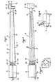
- a dynamometer whose test body is constituted by a bending beam 10 which has a recessed end 12 and which is elastically deformable in bending under the effect of a force Q applied to its opposite end 14.
- the beam 10 has a bending zone 16, of frustoconical shape, lying between two parts 18 and 20, of reduced section, located respectively near the ends 12 and 14.
- the embedded end 12 is cylindrical or else a prism of square section which includes a through passage 22 opening out near the part 18 and intended for the introduction of an electric cable 24 for supplying the sensitive means, which will be described further.
- the opposite end 14 generally takes the form of a straight prism provided with an extension 26 in which a blind hole 28 is internally threaded. This blind hole is intended to fix the end 14 to a support or to a load receptor, as will be described later.
- the beam 10 is made of a material endowed with elastic properties preferably in an anodisable light alloy.
- the bending zone 16 of the beam 10 tends to bend under the action of the load Q which is applied to the end 14.
- This is thus defined in the bending zone a plane of neutral fibers XX which passes through the axis of the frustoconical bending zone and which is perpendicular to the direction of the load Q.
- tensile fibers which lie above the plane of fibers neutral XX and compressed fibers which lie below the plane of neutral fibers XX.
- the extreme fibers 30 and 32 which correspond to two opposite generatrices of the frustoconical zone 16 arranged on either side of the plane XX, undergo the maximum tension and the maximum compression respectively.
- the dynamometer shown in Figures 1 and 2 further includes sensitive means for detecting the flexural deformation of the beam 10.
- sensitive means comprise on the one hand two series of windings 34 and 36 of pre-tensioned gauge wire having their main strands oriented substantially perpendicular to the applied force Q and remaining in intimate contact with the beam 10 in the bending zone 16, the series of windings 34 and 36 having their main strands arranged along the stretched fibers of the bending beam.
- the sensitive means also comprise two series of windings 38 and 40 of pre-tensioned gauge wire having their main strands oriented substantially perpendicular to the applied force Q and remaining in intimate contact with the beam 10 in the bending zone 16 , these two series of windings having their main strands arranged along the compressed fibers of the beam 10.
- One of the two series of windings, namely the series of windings 38 is partially visible in FIG. 1.
- the aforementioned series of windings are supported on anchoring zones machined in the same material of the beam 10, and in the vicinity respectively of its embedded end 12 and its opposite end 14.
- the series of windings 34 rests on two anchoring zones constituted by two shoulders 48 and 50 machined in the material of the beam 10, in the bending zone 16, near the embedded end 12 and the end opposite 14.
- the series of windings 36 is supported on an anchor 52 disposed near the recessed end 22 and on the above-mentioned anchor 50.
- the anchors 48 and 52 are located in the immediate vicinity on either side of the generator 30 constituting the extreme fiber of the bending beam 10.
- the series of windings 34 and 36 may each comprise either a single winding, or several windings which allows either to obtain high bridge resistances, or to reduce the bent length of the beam for a given resistance, as has already been indicated above.
- the two series of windings, such 38, which are arranged along the stretched fibers of the bending beam 10 are supported respectively on two anchors such 54 arranged in close proximity to the embedded end 12 and on either side of the generator 32 and on a common anchor 56 disposed in the immediate vicinity of the opposite end 14.
- These two series of windings constitute the counterparts of the series of windings 34 and 36 but are arranged according to the compressed fibers of the beam instead of be arranged along the stretched fibers of the beam.
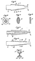
- the four series of windings of aforementioned pre-tensioned gauge wire remaining in intimate contact with the bending zone 16, are wound continuously around the above-mentioned anchors and are connected in an electrical bridge installation, of the Wheatstone bridge type such as represented in FIG. 3. These four series of windings are connected to a sensitivity compensation winding 58, arranged around the part 18, the electrical supply of the assembly being made by means of the cable 24.
- the series of windings 34 and 36 constitute compressed strands 34 and 36 designated by the letter T in FIG. 3 and likewise the two other series of windings 38 and 40 constitute compressed strands designated by the letter C in FIG. 3
- the strands T are located in opposite arms of the bridge assembly, as are the strands C.
- the bridge assembly as shown in FIG. 3, constitutes a conventional assembly. It will be recalled that, apart from any load applied to the bending beam 10, the Wheatstone bridge is balanced, that is to say that the nominal resistances of the strands T and of the strands C are equal.
- the mounting of these four series of windings in an interleaved manner makes it possible to obtain maximum sensitivity when measuring the potential difference V Q -V N which must be zero at rest. Its value, measured for example by means of a precision voltmeter V, makes it possible to measure the cumulative variations of the resistances C and T due to the flexural elongations induced by the applied load.
- the anchors used to hold the series of windings are preferably circular shoulders machined from the material of the beam, according to the technique already described in EP-A-0035942.
- Figure 4 shows a machining of such a circular shoulder by means of a drill bit 60 rotated and allowing to perform an annular removal of material.
- This drill bit is arranged at an angle a with respect to the normal to the corresponding generatrix of the bending zone 16, so as to form a retaining edge for the series or series of windings bearing on this shoulder.
- glue, varnish or similar product it will be possible to facilitate the retention of the series of windings on the anchors by optionally having glue, varnish or similar product.
- the stress field is roughly uniform along each wire in the series of windings.
- the stress field along the generatrices of the truncated cone varies little over the usual lengths for gauge wires, the maximum stress being able to be situated between the two ends and towards the middle. This constitutes a favorable characteristic for the fidelity of the dynamometer, because it is always preferable that the anchors of the gauge wire are little or not at all stressed by the constraints.
- the proportions of the frustoconical flexion zone can be determined by calculation as a function of the zone where it is desired that the stress be maximum.
- the frustoconical shape constitutes the preferred shape of the bending zone of the beam used in the invention.
- FIG. 5 generally shows an elevation view of a flexing beam 10 with decreasing section from the embedded end 12 to the opposite end 14.
- the flexion zone 16 can be a frustoconical shape 62 provided with four millings at 45 °, 64, 66, 68 and 70.
- FIG. 7 shows a bending beam with decreasing elliptical section 72.
- FIG. 8 shows a bending beam with decreasing rectangular section 74.
- the bending beams according to FIGS. 5 to 8 can receive two series of windings such as 34 arranged along the stretched fibers of the beam and two series of windings such as 38 arranged according to the compressed fibers of the bending beam.
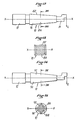
- FIG. 9 shows a bending beam with a frustoconical bending zone which is provided with an axial bore 76, which makes it possible either to increase the sensitivity of the sensor for a given external shape, or to act on its sensitivity by abrasion to inside the hole, for example with a round file, without any risk for the series of windings wound outside the bending beam.
- an axial bore can be produced in other forms of beams, whether of decreasing section or of constant section.
- Figures 10 and 11 show another example of a bending beam, the bending zone of which has a decreasing section.
- the section has the shape of a 1.
- the two opposite wings, 78 and 80, of the beam in 1 allow the establishment of the four series of windings of pre-tensioned gauge wire.
- the wing 78 receives the two series of windings 34 and 36 whose main strands constitute stretched strands
- the wing 80 receives the two series of windings 38 and 40 whose main strands constitute the compressed strands.
- the bending beams of the I-beam type favor the amplitude of the signal from the dynamometer while presenting the same possibilities as the other forms mentioned above for the winding of the resistant wires.
- such a shape makes it possible to achieve an obvious saving in materials, the core of 1 being sufficient to withstand the force located in its plane.
- Figures 12 and 13 show a bending beam 10 whose bending zone 16 has the shape of a trunk of a pyramid with a rectangular base. Two of the sides, namely the sides 82 and 84, of the base are oriented parallel to the plane XX of neutral fibers of the beam.
- Figures 14 and 15 show another example of a bending beam whose bending zone has a truncated pyramid shape.
- This pyramid trunk has a square base whose sides 86, 88, 90 and 92 are oriented at 45 ° relative to the plane of neutral fibers XX of the beam.
- This beam could also have a diamond-shaped base.
- FIGS. 16 and 17 illustrate the mounting of a bending beam dynamometer 10 according to the invention in a load receptor 94 with a deformable parallelogram, of a type known per se.
- the load receptor 94 has a generally parallelepiped shape, made of an elastically deformable material, this shape being provided with a circular hole 96 of large diameter and four circular holes 98, 100, 102 and 104, of small diameter, made at the periphery of the orifice 96.
- Four elastic hinges 106, 108, 110 and 112 are thus produced at the four vertices of a deformable parallelogram.
- This deformable parallelogram has two opposite arms 114 and 116 and two opposite arms 118 and 120.
- the load receptor 94 is fixed on a base 122 and also receives a tray support 124 intended to receive a load Q.
- the bending beam 10 the bending zone of which can be for example frustoconical, is mounted in such a way that its end 12 is embedded in the arm 114 of the deformable parallelogram and that its end 14 is mechanically connected to the opposite arm 116 of the deformable parallelogram .
- the embedded end 12 is mechanically clamped, glued, welded, or screwed into a through hole 126 formed through the arm 114 of the parallelogram and the opposite end of the bending beam passes through a hole 128, of larger dimension, formed in the opposite arm 116.
- the end 14 of the bending beam 10 is fixed, by means of a screw 130 introduced into the blind hole 28 (cf. FIG.
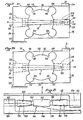
- FIG. 18 shows an embodiment substantially similar to that of FIGS. 16 and 17, but which differs mainly from this by the fact that the opposite end 14 is also embedded in the orifice 128.
- the beam 10 then comprises a thinning 138 , disposed between the bending zone 16 and the opposite end 14 and playing the role of elastic articulation.
- the end 14 can be, like the end 12, clamped, glued, screwed or welded in the orifice 128.
- the dynamometer shown in FIG. 18 further comprises a protective bellows 140 surrounding the bending zone 16 of the beam 10.
- the bellows 140 is fixed at its two ends on two rings 142 and 144 which are themselves screwed or glued respectively in the holes 126 and 128.
- the bellows 140 and the two rings 142 and 144 are shown in half-section in FIG. 18.
- FIG. 19 illustrates another variant which is similar to that of FIGS. 16 and 17.
- the embedded end 12 has a conical shape and is fitted into an orifice 126 of corresponding conical shape.
- the opposite end 14 is connected to the arm 116 of the deformable parallelogram by an elastic plate 132, in the same way as in FIGS. 16 and 17.
- FIG. 20 illustrates another variant of the assembly in which the ends 12 and 14 are both frustoconical and fitted into corresponding frustoconical orifices 126 and 128.
- the bending beam 10 then has a thinning 138, similar to that shown in the figure 18, arranged between the bending zone 16 and the opposite end 14.
- the dynamometers of FIGS. 16 to 20 can receive any bending beam, with decreasing or constant section, as mentioned above.
- the bellows 140 shown in FIG. 18 can be associated with the dynamometers in FIGS. 16 and 17 as well as with those in FIGS. 19 and 20.
- the mounting of the dynamometer of the invention in a load receptor with a deformable parallelogram allows the load receptor to benefit from the low cost and the insensitivity to creep of the bending beam of the invention.
- the load receptor itself can be made of a metal endowed with elastic properties, but different from the metal constituting the bending beam.
- FIG. 21 shows a load receptor, of the bathroom scale type, comprising a base 146, a load-bearing plate 148 and a bending beam 150 which has one end 152 embedded in a vertical extension 153 of the base 146 and an opposite end 154 embedded in a vertical extension 156 of the plate 148.
- the bending beam 150 comprises two bending zones 158 and 160, both of frustoconical shape, and arranged in opposition.
- the zones 158 and 160 are separated by a cylindrical section 162 and by two reduced sections 164 and 166.
- the bending zones 158 and 160 include anchoring zones and receive series of windings of gauge wire.
- the beam 158 receives a series of windings 168 whose main strands are arranged along the stretched fibers of the beam and a series of windings 170 whose main strands are arranged along the compressed fibers of the beam.
- the bending zone 160 receives a series of windings 172 whose main strands are arranged along the compressed fibers of the beam and a series of windings 174 whose main strands are arranged along the stretched fibers of the beam.
- the series of windings 168, 170, 172 and 174 are mounted in an electrical bridge arrangement similar to that shown in Figure 3.
- the series of windings 168 and 174 form two opposite arms of the bridge while the series of windings 170 and 172 form the other two opposite arms of the bridge.
- the two bending zones 158 and 160 of the bending beam 160 can be zones of decreasing section or of constant section, as described above.
- the beam can be arranged vertically between the two horizontal arms of the parallelogram, the other two arms of the parallelogram being inclined relative to the vertical.
- the mechanical connection possibly used to connect the opposite end of the beam to an arm of the parallelogram can be not only an elastic blade, for example a steel blade, but also a link with a rod with knives and needles, or even a wire or cable.
- the dynamometer of the invention allows the production of a varied range of industrial dynamometers and swinging articles, in particular scales.
Landscapes
- Physics & Mathematics (AREA)
- General Physics & Mathematics (AREA)
- Investigating Strength Of Materials By Application Of Mechanical Stress (AREA)
- Micromachines (AREA)
- Measurement Of Force In General (AREA)
Priority Applications (1)
| Application Number | Priority Date | Filing Date | Title |
|---|---|---|---|
| AT83400446T ATE19553T1 (de) | 1982-03-09 | 1983-03-04 | Biegungsbalkendynamometer. |
Applications Claiming Priority (2)
| Application Number | Priority Date | Filing Date | Title |
|---|---|---|---|
| FR8203920 | 1982-03-09 | ||
| FR8203920A FR2523304A1 (fr) | 1982-03-09 | 1982-03-09 | Dynamometre a poutre de flexion |
Publications (2)
| Publication Number | Publication Date |
|---|---|
| EP0088688A1 EP0088688A1 (fr) | 1983-09-14 |
| EP0088688B1 true EP0088688B1 (fr) | 1986-04-30 |
Family
ID=9271780
Family Applications (1)
| Application Number | Title | Priority Date | Filing Date |
|---|---|---|---|
| EP83400446A Expired EP0088688B1 (fr) | 1982-03-09 | 1983-03-04 | Dynamomètre à poutre de flexion |
Country Status (7)
| Country | Link |
|---|---|
| US (1) | US4478093A (enExample) |
| EP (1) | EP0088688B1 (enExample) |
| JP (1) | JPS58189534A (enExample) |
| AT (1) | ATE19553T1 (enExample) |
| CA (1) | CA1190763A (enExample) |
| DE (1) | DE3363250D1 (enExample) |
| FR (1) | FR2523304A1 (enExample) |
Families Citing this family (10)
| Publication number | Priority date | Publication date | Assignee | Title |
|---|---|---|---|---|
| US4788868A (en) * | 1986-03-27 | 1988-12-06 | The Charles Stark Draper Laboratory, Inc. | Strain measurement apparatus and method |
| CH675477A5 (enExample) * | 1988-04-12 | 1990-09-28 | Scaime | |
| US4912983A (en) * | 1989-03-20 | 1990-04-03 | E. I. Du Pont De Nemours And Company | Sealed tensiometer |
| US5187987A (en) * | 1991-11-19 | 1993-02-23 | The Pennsylvania Research Corporation | Bending beam creep test device with piston having a gas bearing |
| US5608172A (en) * | 1995-03-16 | 1997-03-04 | Texas Instruments Incorporated | Die bond touch down detector |
| JP4247554B2 (ja) * | 2003-07-30 | 2009-04-02 | 独立行政法人理化学研究所 | メカノケミカル式センサー |
| DE102010025523A1 (de) * | 2010-06-29 | 2011-12-29 | Voith Patent Gmbh | Kraftaufnehmer |
| CN109029812A (zh) * | 2018-07-25 | 2018-12-18 | 付爱芝 | 一种锚板应力传感器及预应力系统测量装置 |
| WO2021242946A1 (en) | 2020-05-27 | 2021-12-02 | Stryker Corporation | Lift systems and load cells for patient support apparatus |
| US11874192B2 (en) * | 2021-08-04 | 2024-01-16 | Vishay Advanced Technologies Ltd. | Elongate force sensor assembly with throughgoing bore |
Family Cites Families (14)
| Publication number | Priority date | Publication date | Assignee | Title |
|---|---|---|---|---|
| US2544738A (en) * | 1945-08-02 | 1951-03-13 | Lester M Tint | Force measuring device |
| CH304064A (fr) * | 1952-01-15 | 1954-12-31 | Centre Nat Rech Scient | Comparateur électromécanique de précision permettant la mesure à distance. |
| GB757211A (en) * | 1953-07-06 | 1956-09-19 | Elliott Brothers London Ltd | Improvements in electrical strain gauge load-measuring devices |
| US2761670A (en) * | 1955-01-31 | 1956-09-04 | Charles Testut Ets | Electrical load weighing apparatus |
| FR1156671A (fr) * | 1955-09-09 | 1958-05-20 | Vyzk A Zkusebni Letecky Ustav | élément mesureur pour la mesure de forces |
| FR1542997A (fr) * | 1967-10-23 | 1968-10-18 | Dynamomètre à jauges en fil électrique résistant | |
| US3805604A (en) * | 1973-04-25 | 1974-04-23 | A Ormond | Load cell and flexure means for transferring force thereto |
| US3832898A (en) * | 1973-09-24 | 1974-09-03 | G Randolph | Dual-mount electromechanical deflection sensor |
| US3878711A (en) * | 1973-09-24 | 1975-04-22 | Jr George J J Randolph | Extensometer |
| FR2439395A1 (fr) * | 1978-10-19 | 1980-05-16 | Testut Aequitas | Dynamometre a isolation electrique par anodisation |
| FR2469701B1 (fr) * | 1979-11-16 | 1986-03-14 | Testut Aequitas | Recepteur de charge a parallelogramme realise en une seule piece et applicable notamment aux balances a usage commercial |
| FR2477708A1 (fr) * | 1980-03-07 | 1981-09-11 | Testut Aequitas | Dynamometre a fil de jauge enroule et branche dans un montage electrique en pont |
| FR2485191A2 (fr) * | 1980-06-20 | 1981-12-24 | Testut Aequitas | Dynamometre a fil de jauge enroule et branche dans un montage electrique en pont |
| US4411162A (en) * | 1980-03-07 | 1983-10-25 | Testut Aequitas | Gauge wire dynamometer wound and connected in an electrical bridge arrangement |
-
1982
- 1982-03-09 FR FR8203920A patent/FR2523304A1/fr active Granted
-
1983
- 1983-02-18 CA CA000421899A patent/CA1190763A/en not_active Expired
- 1983-03-04 AT AT83400446T patent/ATE19553T1/de not_active IP Right Cessation
- 1983-03-04 DE DE8383400446T patent/DE3363250D1/de not_active Expired
- 1983-03-04 EP EP83400446A patent/EP0088688B1/fr not_active Expired
- 1983-03-07 US US06/472,447 patent/US4478093A/en not_active Expired - Fee Related
- 1983-03-09 JP JP58038903A patent/JPS58189534A/ja active Pending
Also Published As
| Publication number | Publication date |
|---|---|
| ATE19553T1 (de) | 1986-05-15 |
| FR2523304A1 (fr) | 1983-09-16 |
| EP0088688A1 (fr) | 1983-09-14 |
| DE3363250D1 (en) | 1986-06-05 |
| CA1190763A (en) | 1985-07-23 |
| FR2523304B1 (enExample) | 1984-08-03 |
| JPS58189534A (ja) | 1983-11-05 |
| US4478093A (en) | 1984-10-23 |
Similar Documents
| Publication | Publication Date | Title |
|---|---|---|
| EP0088688B1 (fr) | Dynamomètre à poutre de flexion | |
| EP1056985B1 (fr) | Capteur d'extensiometrie destine a mesurer des deformations a calage mecanique de premiere pose et calibrage automatique en fonction de ce calage | |
| CH620028A5 (enExample) | ||
| FR2942316A1 (fr) | Capteur de force de contact | |
| EP1992906A1 (fr) | Extensomètre a réseau de bragg et dispositif de mesure comportant au moins un tel extensomètre | |
| EP0017581A1 (fr) | Récepteur de charge à parallélogramme d'une seule pièce et à transducteur capacitif | |
| EP0634624A1 (fr) | Outil pour mesurer une force de serrage exercée par une tige mobile d'appareil de mesure de longueur | |
| WO2001077618A1 (fr) | Inclinometre a reseau de bragg | |
| EP0376795B1 (fr) | Capteur extensométrique de mesure de contraintes pour élément de forage | |
| EP0029776B1 (fr) | Récepteur de charge à parallélogramme réalisé en une seule pièce | |
| EP0401133B1 (fr) | Dispositif de pesage à jauges de contrainte | |
| FR2918174A1 (fr) | Alignement dans une machine d'essai de fatigue en traction | |
| EP1519806A2 (fr) | Dispositif de fixation d'une fibre rigide et fragile comprenant une gaine mecaniquement deformable et susceptible d etre soumise a au moins une contrainte mecanique | |
| FR2579327A1 (fr) | Dispositif perfectionne d'essais de traction biaxiale | |
| WO1994017382A1 (fr) | Capteur de force | |
| EP3498661B1 (fr) | Dispositif microelectromecanique et/ou nanoelectromecanique offrant une robustesse augmentee | |
| FR2888339A1 (fr) | Capteur sismique a fibre optique | |
| FR2605736A1 (fr) | Poutrelle de jauge de contrainte avec protection contre les surcharges incorporee | |
| EP0390648B1 (fr) | Capteur de contact multidirectionnel pour machines de contrôle | |
| EP0094290A2 (fr) | Récepteur de charge à parallélogramme déformable | |
| EP0035942B1 (fr) | Dynamomètre à fil de jauge enroulé et branché dans un montage électrique en pont | |
| FR2689642A1 (fr) | Capteur d'accélération du type capacitif omnidirectionnel dans un plan principal. | |
| EP0291365A1 (fr) | Capteur de moments de flexion-torsion | |
| FR2495771A1 (fr) | Dynamometre a corps d'epreuve deformable | |
| FR2751411A1 (fr) | Systeme mecanique d'application d'efforts sur des pistes subissant en outre les sollicitations de contact |
Legal Events
| Date | Code | Title | Description |
|---|---|---|---|
| PUAI | Public reference made under article 153(3) epc to a published international application that has entered the european phase |
Free format text: ORIGINAL CODE: 0009012 |
|
| AK | Designated contracting states |
Designated state(s): AT BE CH DE FR GB IT LI LU NL SE |
|
| 17P | Request for examination filed |
Effective date: 19840213 |
|
| GRAA | (expected) grant |
Free format text: ORIGINAL CODE: 0009210 |
|
| AK | Designated contracting states |
Kind code of ref document: B1 Designated state(s): AT BE CH DE FR GB IT LI LU NL SE |
|
| REF | Corresponds to: |
Ref document number: 19553 Country of ref document: AT Date of ref document: 19860515 Kind code of ref document: T |
|
| ITF | It: translation for a ep patent filed | ||
| REF | Corresponds to: |
Ref document number: 3363250 Country of ref document: DE Date of ref document: 19860605 |
|
| PG25 | Lapsed in a contracting state [announced via postgrant information from national office to epo] |
Ref country code: AT Effective date: 19870304 |
|
| PG25 | Lapsed in a contracting state [announced via postgrant information from national office to epo] |
Ref country code: SE Effective date: 19870305 |
|
| PLBE | No opposition filed within time limit |
Free format text: ORIGINAL CODE: 0009261 |
|
| STAA | Information on the status of an ep patent application or granted ep patent |
Free format text: STATUS: NO OPPOSITION FILED WITHIN TIME LIMIT |
|
| PG25 | Lapsed in a contracting state [announced via postgrant information from national office to epo] |
Ref country code: LU Free format text: LAPSE BECAUSE OF NON-PAYMENT OF DUE FEES Effective date: 19870331 Ref country code: LI Effective date: 19870331 Ref country code: CH Effective date: 19870331 |
|
| 26N | No opposition filed | ||
| BERE | Be: lapsed |
Owner name: TESTUT-AEQUITAS Effective date: 19870331 |
|
| PG25 | Lapsed in a contracting state [announced via postgrant information from national office to epo] |
Ref country code: NL Effective date: 19871001 |
|
| NLV4 | Nl: lapsed or anulled due to non-payment of the annual fee | ||
| GBPC | Gb: european patent ceased through non-payment of renewal fee | ||
| PG25 | Lapsed in a contracting state [announced via postgrant information from national office to epo] |
Ref country code: FR Free format text: LAPSE BECAUSE OF NON-PAYMENT OF DUE FEES Effective date: 19871130 |
|
| REG | Reference to a national code |
Ref country code: CH Ref legal event code: PL |
|
| PG25 | Lapsed in a contracting state [announced via postgrant information from national office to epo] |
Ref country code: DE Effective date: 19871201 |
|
| REG | Reference to a national code |
Ref country code: FR Ref legal event code: ST |
|
| PG25 | Lapsed in a contracting state [announced via postgrant information from national office to epo] |
Ref country code: GB Effective date: 19881122 |
|
| PG25 | Lapsed in a contracting state [announced via postgrant information from national office to epo] |
Ref country code: BE Effective date: 19890331 |
|
| EUG | Se: european patent has lapsed |
Ref document number: 83400446.7 Effective date: 19880215 |