EP0088429B1 - Postage meter having non-volatile memory for containing a serial number - Google Patents
Postage meter having non-volatile memory for containing a serial number Download PDFInfo
- Publication number
- EP0088429B1 EP0088429B1 EP83102266A EP83102266A EP0088429B1 EP 0088429 B1 EP0088429 B1 EP 0088429B1 EP 83102266 A EP83102266 A EP 83102266A EP 83102266 A EP83102266 A EP 83102266A EP 0088429 B1 EP0088429 B1 EP 0088429B1
- Authority
- EP
- European Patent Office
- Prior art keywords
- serial number
- meter
- postage meter
- computing means
- message
- Prior art date
- Legal status (The legal status is an assumption and is not a legal conclusion. Google has not performed a legal analysis and makes no representation as to the accuracy of the status listed.)
- Expired
Links
Images

Classifications
-
- G—PHYSICS
- G07—CHECKING-DEVICES
- G07B—TICKET-ISSUING APPARATUS; FARE-REGISTERING APPARATUS; FRANKING APPARATUS
- G07B17/00—Franking apparatus
- G07B17/00733—Cryptography or similar special procedures in a franking system
-
- G—PHYSICS
- G07—CHECKING-DEVICES
- G07B—TICKET-ISSUING APPARATUS; FARE-REGISTERING APPARATUS; FRANKING APPARATUS
- G07B17/00—Franking apparatus
- G07B17/00185—Details internally of apparatus in a franking system, e.g. franking machine at customer or apparatus at post office
- G07B17/00362—Calculation or computing within apparatus, e.g. calculation of postage value
-
- G—PHYSICS
- G07—CHECKING-DEVICES
- G07B—TICKET-ISSUING APPARATUS; FARE-REGISTERING APPARATUS; FRANKING APPARATUS
- G07B17/00—Franking apparatus
- G07B17/00733—Cryptography or similar special procedures in a franking system
- G07B2017/00935—Passwords
Definitions
- the present invention relates to electronic postage meters having a non-volatile memory adapted to contain therein a serial number for the meter.
- Electronic postage meter systems have been developed, as for example the systems disclosed in USA3 978 457, in US-A-3 938 095, in US-A-4 301 507 and in EP-A-0 019 515.
- Each of the electronic postage meters disclosed in the above-identified applications and patents includes a non-volatile memory for storing critical information when power is not applied to the meter.
- Various types of accounting information may be stored in the meter's non-volatile memory. This information includes, for example, the amount of postage remaining in the meter for subsequent printing and the total amount of postage printed by the meter.
- Other types of accounting or operating data may also be stored in the non-volatile memory.
- the function served by the non-volatile memory circuits have replaced and enhanced the functions of the mechanical accounting registers or wheels utilized in previous mechanical type postage meters.
- a non-volatile memory chip number is entered into the non-volatile memory and is used during the assembly of the meter.
- the meter itself is assembled with the final serial number on the meter body, still utilizing a non-volatile memory with a given chip number and entered in the serial number field.
- the final serial number is communicated to the meter.
- a flag bit can be set if the path to the serial number in the non-volatile memory is to be closed off so that the data field in the non-volatile memory occupied by the serial number cannot be written into. That is, writing into non-volatile memory data field containing the serial number is prevented.
- the object of the invention is to provide a postage meter which enables changing of the serial number in the one meter until it is finally determined that the entered serial number is correct.
- a postage meter which comprises printing means for printing postage, a computing means coupled to said printing means for accounting for postage printed by said printing means, non-volatile memory means coupled to said computing means and a program store coupled to said computing means and adapted to store programs to control the operation of said computing means
- said program store contains a program operable to cause said computing means to compare a serial number message including an operational indicator bit entered into the postage meter with a previously entered postage meter serial number and operable to cause said computing means to set a lock bit preventing re-entry into said program if a comparison is obtained in the condition where an operational indicator bit in said entered serial number message is set to indicate a desire to utilize the entered serial number.
- Fig. 1 is a perspective view of a postage meter adapted to utilize the present invention.
- An electronic postage meter 2 is removably secured to a postage meter base 4.
- a slot 6 is provided between the postage meter 2 and the base 4 at the forward edge thereof, for receiving envelopes or the like for the printing of postage thereon.
- the postage meter is provided with a display panel 8, preferably an electronic display device, as well as a control panel or keyboard 10.
- the meter 2 includes a service mode switch 12. Power is applied to the meter 2 via a AC power line cord 14 when the meter power switch 15 is turned on.
- the meter also includes a communications port 16 which is connected by a communications cable 18 to an external message generator 20.
- the message generator is removable from the meter by detaching the cable 18 from the communications port 16. Communications between the meter 2 and the external message generator 20 may be in accordance with the serial communication echoplex technique described in US-A-4 301 507.
- the operation of the keyboard 10 of the electronic postage meter 2 differs from that of the keyboard 22 of the external message generator 20.
- the external message generator keyboard 22, with its unique keys 24 can invoke a routine in a read only memory in the external message generator 20 to generate a message with a unique header and format suitable to invoke a particular function in the electronic postage meter 2. That is, the keyboard 22 of the external message generator 20 can cause a message to be generated by the external message generator and communicated over communications channel 18 to the meter to invoke a routine stored in the non-volatile memory of the electronic meter 2 which cannot be invoked by actuation of the meter keyboard 10.
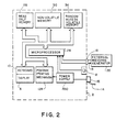
- FIG. 2 is a block diagram showing one arrangement of the internal major components of an electronic meter embodying the present invention.
- the electronic postage meter 2 is controlled by a microprocessor 26 operated under control of a series of programs stored in a read only memory 28. Connected to the microprocessor are the keyboard 8 and display 10 as well as a postage printing mechanism 128.
- the microprocessor accepts information entered via the keyboard or via the communications port 16 from an external message generator, such as the external message generator 20, over the communications channel 18.
- Critical accounting and other information is stored in a non-volatile memory 30.
- the non-volatile memory may be an MOS semi-conductor type memory, a battery augmented CMOS memory, or other suitable non-volatile memory component.
- the function of the non-volatile memory 30 is to store critical postage meter data during those times when the power is not applied to the meter.
- This data may include, in addition to the serial number of the meter, information as to the amount of the descending register (the amount of postage available for printing), the value of the ascending register (the total amount of postage printed by the meter), and the value of the piece count register (the total number of cycles the meter has performed), as well as other types of data, such as service information, which are desired to be retained in the memory when no power is applied to the meter.
- the meter power switch 15 When the meter power switch 15 is turned on causing the power supply 130 internal to the meter to energize the microprocessor 26 and the postage printing mechanism 28, the information stored in the non-volatile memory 30 is transferred via the microprocessor to a volatile random access memory 34.
- the volatile, random access memory 34 after power up contains an image of copy of the information stored in the non-volatile memory 30 prior to energization.
- the data in the volatile, random access memory 34 is modified. Accordingly, when postage is printed, the descending register will be decremented, the ascending register incremented and the piece counter register incremented.
- the modified image the current updated data in the volatile, random access memory 34 is transferred via the microprocessor back into the non-volatile memory 30.
- the data is transferred into a suitably prepared area of the non-volatile memory.
- the non-volatile memory 30 is updated during the power down cycle when the power switch 15 is turned off.
- a like transfer of information between the non-volatile memory 30 and the volatile, random access memory 34 also occurs when the service mode switch 12 is actuated.
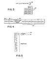
- Non-volatile memory 30 of the meter Contained in the non-volatile memory 30 of the meter are seven nibbles 36 which are reserved for the serial number. Also contained in non-volatile memory 30 is an additional bit position 38 which is reserved for the lock indicator. The placement of the serial number is shown by the indicators of the binary coded digit, where BCD 7 is the most significant digit of the serial number and BCD 1 is the least significant digit.
- the firmware logic of the meter causes the non-volatile memory 30 to be prepared to have new or modified service data written into the non-volatile memory.
- the service field contains the serial number location. It should be recognized that when the present invention is utilized with electronic postage meters of the type shown in US-A-4 301 507 (ELECTRONIC POSTAGE METER HAVING PLURAL COMPUTING SYSTEMS), the service mode switch described therein, as well as in US-A-4 280 180 (ELECTRONIC POSTAGE METER HAVING FIELD SETTABLE CONTROL VALUES), is left in the operational mode as proposed to the service mode. This causes the external communications channel to remain operative. The entry into the service routine is achieved by the transmission of a service routine message from the external message generator 20.
- the meter is of the type wherein the information from non-volatile memory 30 is read during power up to the meter (when the meter power switch 15 is turned ON) and transferred back to non-volatile memory 30 during the change from the operational to the service mode of the meter (when the meter service switch 12 is moved from the operational to the service position). At all other times, a current copy of the image of this information is in the volatile, random access memory 34 of the meter. Changes are made to the image of the information in the volatile random access memory 34. During the power down of the meter (when the meter power switch 15 is turned OFF) or mode change (service to operate or operate to service), the information in the volatile random access memory 34 is written into the non-volatile memory 30.
- the enter serial number message consists of a one byte (eight bits) header or identifier 40, a format byte 42 and four data bytes 44 for a total of six bytes. Contained in the four data bytes 44 are a BCD operational indicator 46 and seven binary coded digits, two per byte, representing the serial number. Header 40, format 42 and data bytes 44 are as generally described in the aforementioned US-A-4 320 507.
- the header 40 provides identification of the unique message that is to follow, here, the fact that the message constitutes the serial number.
- the format byte 42 contains two BCD digits indicating the number of data digits to follow and the placement of the decimal point within these digits. In the present case of the serial number, there is no decimal point, therefore, the decimal point position indicator will be shown as containing four one or a hex F in decimal point indicator position.
- the operational indicator BCD digit 46 indicates to the meter, operating under the control of the firmware program contained in the read only memory 28, which operation (change the serial number or lock the serial number) is to be performed. A zero will indicate a desire to change the serial number and a one will indicate a desire to lock the serial number. Codes 2 HEX thru F HEX of the operational indicator are undefined and will cause the meter to return a procedural error message.
- FIG. 5 This is depicted in Figure 5 wherein a table of codes is shown for the operational indicator BCD digit. Only the first two codes 48 and 50 as previously noted will cause the meter to operate in accordance with the program routine to be described hereinafter. Utilization of any of the additional codes shown will cause the meter to return an error message.
- This error message is a procedural error message which disappears after a timed period or reinitialization of the meter as opposed to a fatal error message which will cause the meter to become inoperative for the remainder of the power on period or to lock up.
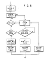
- the external message generator After the meter has been placed in the service mode by an externally generated message (the external message) and with the service switch in the operational mode, the external message generator generates a serial number message.
- the firmware program of the meter Upon receipt of the serial number message, the firmware program of the meter causes the meter to check the message for proper formatting and returns a procedural error message if the format is not acceptable. If the format is acceptable, the firmware program causes the meter to examine the condition of the lock bit which was stored in non-volatile memory 30. If this lock bit is set, the meter returns a procedural error message. If the lock bit is not set, the firmware program then causes the meter to examine the operational indicator hex digit 46 contained in the serial number message.
- the meter will change the serial number information in the volatile random access memory image to correspond to the serial number contained in the message. The meter will then return a status message to the external message generator. If the operational indicator bit is set to the hex digit 1, the firmware will cause the meter to compare the serial number data in the volatile random access memory 34 with the serial number data contained in the message. If the comparison is positive, the meter will set the non-volatile memory lock bit in its image in the volatile random access memory and return a status message to the external message generator. All other conditions that are tested and failed will return a procedural error message and will not set the non-volatile memory lock bit in its image in the volatile random access memory 34.
- the serial number message format includes an operational BCD digit as an operational indicator. If the serial number has been entered and the operational indicator set to zero, the serial number will be changed to the value contained in the data message. If the operational indicator is a one, the firmware will examine the serial number presently contained in non-volatile memory, and compare it with the value contained in the serial number message. If the result is favourable or true, the program will set the non-volatile memory lock bit thus preventing further access to this program.
- the information containing the serial number or the serial number and lock bit contained in the data in the volatile random access memory 34 is written into the non-volatile memory 30 either upon power down of the meter or a mode change.
- the external message generator 20 will send an exit service mode signal message to the meter. This message will cause the image in th volatile random access memory 34 to be written into the non-volatile memory 30.
- the meter can be used to check the serial number and all other checks conducted during routine manufacturing shop checks.
- the serial number can if necessary be repeatedly entered, e.g. during production of the meter, until it is determined that the entered number is correct.
- a serial number may be entered into the meter at the end of the manufacturing process after the meter has been assembled and the components tested by actuation of a routine programmed into a read only memory within the meter.
- This routine is used only once during the life of the meter non-volatile memory.
- the routine requires the check of a non-volatile memory bit position which is set once the routine has been successfully completed. The setting of this bit prevents reentry into the one time programe.
- the program can be reused until the bit is set.
- the bit is set by comparison of the data included in a received message with the value of data contained in the memory. If the comparison is true, the bit is set.
- the format of the received message entered into the meter to enter the serial number and set the bit requires an external message generator. The particular message format employed cannot be generated by actuation of the meter keyboard.
- the serial number message format includes one digit as an operational indicator. If the serial number has been entered and the operational indicator is set to zero, the serial number in the random access memory of the meter will be changed to the value contained in the data message. If the operational indicator is set to a one, the firmware will cause the meter to operate to examine the serial number presently contained in the random access memory image of non-volatile memory and compare it with the value contained in the serial number message. If the result is favourable or true, the program will set the non-volatile memory lock bit image in the random access memory thus preventing further access into this program once the image is written into the meter's non-volatile memory.
- postage meter refers to the general definition of a device for the imprinting of a defined unit value for governmental or private carrier, delivery such as parcels or envelopes or other like application for unit value printing.
- postage meter is utilized as it is both known and employed in the trade, as a general term for devices utilized in conjunction with services other than those exclusively provided by governmental postal services.
- private parcel or freight services purchase and employ postal meters as a means to provide unit value printing for and such meters include accounting and printing functions.
Description
- The present invention relates to electronic postage meters having a non-volatile memory adapted to contain therein a serial number for the meter.
- Electronic postage meter systems have been developed, as for example the systems disclosed in USA3 978 457, in US-A-3 938 095, in US-A-4 301 507 and in EP-A-0 019 515. Each of the electronic postage meters disclosed in the above-identified applications and patents includes a non-volatile memory for storing critical information when power is not applied to the meter. Various types of accounting information may be stored in the meter's non-volatile memory. This information includes, for example, the amount of postage remaining in the meter for subsequent printing and the total amount of postage printed by the meter. Other types of accounting or operating data may also be stored in the non-volatile memory. The function served by the non-volatile memory circuits have replaced and enhanced the functions of the mechanical accounting registers or wheels utilized in previous mechanical type postage meters.
- It has been recognised that it may be desirable to enter the serial number into the non-volatile memory of the electronic postage meter only upon completion of the assembly operation.
- In an arrangement described in US-A-4424573, published Jan. 3, 1984, a non-volatile memory chip number is entered into the non-volatile memory and is used during the assembly of the meter. The meter itself, however, is assembled with the final serial number on the meter body, still utilizing a non-volatile memory with a given chip number and entered in the serial number field. When assembly and testing is completed, the final serial number is communicated to the meter. It is also noted that a flag bit can be set if the path to the serial number in the non-volatile memory is to be closed off so that the data field in the non-volatile memory occupied by the serial number cannot be written into. That is, writing into non-volatile memory data field containing the serial number is prevented.
- The object of the invention is to provide a postage meter which enables changing of the serial number in the one meter until it is finally determined that the entered serial number is correct.
- According to the invention, in a postage meter which comprises printing means for printing postage, a computing means coupled to said printing means for accounting for postage printed by said printing means, non-volatile memory means coupled to said computing means and a program store coupled to said computing means and adapted to store programs to control the operation of said computing means, said program store contains a program operable to cause said computing means to compare a serial number message including an operational indicator bit entered into the postage meter with a previously entered postage meter serial number and operable to cause said computing means to set a lock bit preventing re-entry into said program if a comparison is obtained in the condition where an operational indicator bit in said entered serial number message is set to indicate a desire to utilize the entered serial number.
- For a better understanding of the invention and to show how the same may be carried into effect, reference is now made to the drawings in which like reference numerals designate similar elements in various views of a preferred embodiment of the invention, and in which:
- Figure 1 is a perspective view of an electronic postage meter adapted to utilize the present invention;
- Figure 2 is a block diagram showing one arrangement of the internal major components of an electronic postage meter embodying the present invention;
- Figure 3 is a partial memory map of the non-volatile memory shown in Figure 2 depicting placement of the serial number and a one bit serial number lock indicator;
- Figure 4 is a diagrammatic representation of a serial number message including an operational indicator BCD bit digit;
- Figure 5 is a table of codes helpful in understanding the present invention; and
- Figure 6 is a flow chart of the firmware program of the read only memory shown in Fig. 2.
- Reference is now made to Fig. 1. Fig. 1 is a perspective view of a postage meter adapted to utilize the present invention. An
electronic postage meter 2 is removably secured to apostage meter base 4. In this arrangement, aslot 6 is provided between thepostage meter 2 and thebase 4 at the forward edge thereof, for receiving envelopes or the like for the printing of postage thereon. The postage meter is provided with adisplay panel 8, preferably an electronic display device, as well as a control panel orkeyboard 10. - The
meter 2 includes aservice mode switch 12. Power is applied to themeter 2 via a ACpower line cord 14 when themeter power switch 15 is turned on. The meter also includes acommunications port 16 which is connected by acommunications cable 18 to anexternal message generator 20. The message generator is removable from the meter by detaching thecable 18 from thecommunications port 16. Communications between themeter 2 and theexternal message generator 20 may be in accordance with the serial communication echoplex technique described in US-A-4 301 507. - As will be explained in greater detail hereinafter, the operation of the
keyboard 10 of theelectronic postage meter 2 differs from that of thekeyboard 22 of theexternal message generator 20. The externalmessage generator keyboard 22, with itsunique keys 24 can invoke a routine in a read only memory in theexternal message generator 20 to generate a message with a unique header and format suitable to invoke a particular function in theelectronic postage meter 2. That is, thekeyboard 22 of theexternal message generator 20 can cause a message to be generated by the external message generator and communicated overcommunications channel 18 to the meter to invoke a routine stored in the non-volatile memory of theelectronic meter 2 which cannot be invoked by actuation of themeter keyboard 10. - Figure 2 is a block diagram showing one arrangement of the internal major components of an electronic meter embodying the present invention. The
electronic postage meter 2 is controlled by a microprocessor 26 operated under control of a series of programs stored in a readonly memory 28. Connected to the microprocessor are thekeyboard 8 and display 10 as well as apostage printing mechanism 128. The microprocessor accepts information entered via the keyboard or via thecommunications port 16 from an external message generator, such as theexternal message generator 20, over thecommunications channel 18. Critical accounting and other information is stored in anon-volatile memory 30. The non-volatile memory may be an MOS semi-conductor type memory, a battery augmented CMOS memory, or other suitable non-volatile memory component. The function of thenon-volatile memory 30 is to store critical postage meter data during those times when the power is not applied to the meter. This data may include, in addition to the serial number of the meter, information as to the amount of the descending register (the amount of postage available for printing), the value of the ascending register (the total amount of postage printed by the meter), and the value of the piece count register (the total number of cycles the meter has performed), as well as other types of data, such as service information, which are desired to be retained in the memory when no power is applied to the meter. - When the
meter power switch 15 is turned on causing thepower supply 130 internal to the meter to energize the microprocessor 26 and thepostage printing mechanism 28, the information stored in thenon-volatile memory 30 is transferred via the microprocessor to a volatilerandom access memory 34. The volatile,random access memory 34 after power up contains an image of copy of the information stored in thenon-volatile memory 30 prior to energization. During operation of the postage meter, the data in the volatile,random access memory 34 is modified. Accordingly, when postage is printed, the descending register will be decremented, the ascending register incremented and the piece counter register incremented. When thepower switch 15 is turned off, the modified image, the current updated data in the volatile,random access memory 34 is transferred via the microprocessor back into thenon-volatile memory 30. The data is transferred into a suitably prepared area of the non-volatile memory. Thus, thenon-volatile memory 30 is updated during the power down cycle when thepower switch 15 is turned off. A like transfer of information between thenon-volatile memory 30 and the volatile,random access memory 34 also occurs when theservice mode switch 12 is actuated. - Reference is now made to Figure 3. Contained in the
non-volatile memory 30 of the meter are sevennibbles 36 which are reserved for the serial number. Also contained innon-volatile memory 30 is anadditional bit position 38 which is reserved for the lock indicator. The placement of the serial number is shown by the indicators of the binary coded digit, where BCD 7 is the most significant digit of the serial number andBCD 1 is the least significant digit. - When the service mode of the meter is entered via an external message, the firmware logic of the meter causes the
non-volatile memory 30 to be prepared to have new or modified service data written into the non-volatile memory. The service field contains the serial number location. It should be recognized that when the present invention is utilized with electronic postage meters of the type shown in US-A-4 301 507 (ELECTRONIC POSTAGE METER HAVING PLURAL COMPUTING SYSTEMS), the service mode switch described therein, as well as in US-A-4 280 180 (ELECTRONIC POSTAGE METER HAVING FIELD SETTABLE CONTROL VALUES), is left in the operational mode as proposed to the service mode. This causes the external communications channel to remain operative. The entry into the service routine is achieved by the transmission of a service routine message from theexternal message generator 20. - It should be understood that for the purposes of the description of the present invention, the meter is of the type wherein the information from
non-volatile memory 30 is read during power up to the meter (when themeter power switch 15 is turned ON) and transferred back tonon-volatile memory 30 during the change from the operational to the service mode of the meter (when themeter service switch 12 is moved from the operational to the service position). At all other times, a current copy of the image of this information is in the volatile,random access memory 34 of the meter. Changes are made to the image of the information in the volatilerandom access memory 34. During the power down of the meter (when themeter power switch 15 is turned OFF) or mode change (service to operate or operate to service), the information in the volatilerandom access memory 34 is written into thenon-volatile memory 30. - Reference is now made to Figure 4. The enter serial number message consists of a one byte (eight bits) header or
identifier 40, a format byte 42 and fourdata bytes 44 for a total of six bytes. Contained in the fourdata bytes 44 are a BCDoperational indicator 46 and seven binary coded digits, two per byte, representing the serial number.Header 40, format 42 anddata bytes 44 are as generally described in the aforementioned US-A-4 320 507. Theheader 40 provides identification of the unique message that is to follow, here, the fact that the message constitutes the serial number. The format byte 42 contains two BCD digits indicating the number of data digits to follow and the placement of the decimal point within these digits. In the present case of the serial number, there is no decimal point, therefore, the decimal point position indicator will be shown as containing four one or a hex F in decimal point indicator position. - The operational
indicator BCD digit 46 indicates to the meter, operating under the control of the firmware program contained in the read onlymemory 28, which operation (change the serial number or lock the serial number) is to be performed. A zero will indicate a desire to change the serial number and a one will indicate a desire to lock the serial number.Codes 2 HEX thru F HEX of the operational indicator are undefined and will cause the meter to return a procedural error message. - This is depicted in Figure 5 wherein a table of codes is shown for the operational indicator BCD digit. Only the first two
codes - Procedural and fatal errors are described in US-A-4 471 441, published Sept. 9, 1984 and in US-A-4 251 874.
- Referring now to Figure 6, after the meter has been placed in the service mode by an externally generated message (the external message) and with the service switch in the operational mode, the external message generator generates a serial number message. Upon receipt of the serial number message, the firmware program of the meter causes the meter to check the message for proper formatting and returns a procedural error message if the format is not acceptable. If the format is acceptable, the firmware program causes the meter to examine the condition of the lock bit which was stored in
non-volatile memory 30. If this lock bit is set, the meter returns a procedural error message. If the lock bit is not set, the firmware program then causes the meter to examine the operationalindicator hex digit 46 contained in the serial number message. If the operational indicator hex digit is a zero, the meter will change the serial number information in the volatile random access memory image to correspond to the serial number contained in the message. The meter will then return a status message to the external message generator. If the operational indicator bit is set to thehex digit 1, the firmware will cause the meter to compare the serial number data in the volatilerandom access memory 34 with the serial number data contained in the message. If the comparison is positive, the meter will set the non-volatile memory lock bit in its image in the volatile random access memory and return a status message to the external message generator. All other conditions that are tested and failed will return a procedural error message and will not set the non-volatile memory lock bit in its image in the volatilerandom access memory 34. Thus, the serial number message format includes an operational BCD digit as an operational indicator. If the serial number has been entered and the operational indicator set to zero, the serial number will be changed to the value contained in the data message. If the operational indicator is a one, the firmware will examine the serial number presently contained in non-volatile memory, and compare it with the value contained in the serial number message. If the result is favourable or true, the program will set the non-volatile memory lock bit thus preventing further access to this program. - The information containing the serial number or the serial number and lock bit contained in the data in the volatile
random access memory 34 is written into thenon-volatile memory 30 either upon power down of the meter or a mode change. Under normal conditions, theexternal message generator 20 will send an exit service mode signal message to the meter. This message will cause the image in th volatilerandom access memory 34 to be written into thenon-volatile memory 30. After the procedure is completed and theexternal message generator 20 has been removed from themeter 2, the meter can be used to check the serial number and all other checks conducted during routine manufacturing shop checks. - Thus, by use of the invention, the serial number can if necessary be repeatedly entered, e.g. during production of the meter, until it is determined that the entered number is correct.
- This allows adjustment in the case of erroneous key strokes and avoids problems of having meters fail at the final assembly point because of inadvertent errors which would require the entire meter to be disassembled to access the non-volatile memory in the meter.
- A serial number may be entered into the meter at the end of the manufacturing process after the meter has been assembled and the components tested by actuation of a routine programmed into a read only memory within the meter. This routine is used only once during the life of the meter non-volatile memory. The routine requires the check of a non-volatile memory bit position which is set once the routine has been successfully completed. The setting of this bit prevents reentry into the one time programe. The program can be reused until the bit is set. The bit is set by comparison of the data included in a received message with the value of data contained in the memory. If the comparison is true, the bit is set. The format of the received message entered into the meter to enter the serial number and set the bit requires an external message generator. The particular message format employed cannot be generated by actuation of the meter keyboard.
- Preferably the serial number message format includes one digit as an operational indicator. If the serial number has been entered and the operational indicator is set to zero, the serial number in the random access memory of the meter will be changed to the value contained in the data message. If the operational indicator is set to a one, the firmware will cause the meter to operate to examine the serial number presently contained in the random access memory image of non-volatile memory and compare it with the value contained in the serial number message. If the result is favourable or true, the program will set the non-volatile memory lock bit image in the random access memory thus preventing further access into this program once the image is written into the meter's non-volatile memory.
- It should be recognized and understood that as used herein the term postage meter refers to the general definition of a device for the imprinting of a defined unit value for governmental or private carrier, delivery such as parcels or envelopes or other like application for unit value printing. Thus, the term postage meter is utilized as it is both known and employed in the trade, as a general term for devices utilized in conjunction with services other than those exclusively provided by governmental postal services. For example, private parcel or freight services purchase and employ postal meters as a means to provide unit value printing for and such meters include accounting and printing functions.
Claims (8)
Applications Claiming Priority (2)
| Application Number | Priority Date | Filing Date | Title |
|---|---|---|---|
| US06/355,437 US4506329A (en) | 1982-03-08 | 1982-03-08 | Non-volatile memory serial number lock for electronic postage meter |
| US355437 | 1982-03-08 |
Publications (3)
| Publication Number | Publication Date |
|---|---|
| EP0088429A2 EP0088429A2 (en) | 1983-09-14 |
| EP0088429A3 EP0088429A3 (en) | 1986-05-07 |
| EP0088429B1 true EP0088429B1 (en) | 1988-08-24 |
Family
ID=23397438
Family Applications (1)
| Application Number | Title | Priority Date | Filing Date |
|---|---|---|---|
| EP83102266A Expired EP0088429B1 (en) | 1982-03-08 | 1983-03-08 | Postage meter having non-volatile memory for containing a serial number |
Country Status (5)
| Country | Link |
|---|---|
| US (1) | US4506329A (en) |
| EP (1) | EP0088429B1 (en) |
| JP (1) | JPS58172766A (en) |
| CA (1) | CA1193728A (en) |
| DE (1) | DE3377824D1 (en) |
Cited By (2)
| Publication number | Priority date | Publication date | Assignee | Title |
|---|---|---|---|---|
| EP0285390A2 (en) * | 1987-04-03 | 1988-10-05 | Neopost Limited | Franking machine |
| EP1037169A2 (en) | 1999-03-17 | 2000-09-20 | Francotyp-Postalia Aktiengesellschaft & Co. | Method and device for inputting an indicia to a franking machine |
Families Citing this family (16)
| Publication number | Priority date | Publication date | Assignee | Title |
|---|---|---|---|---|
| US4525786A (en) * | 1982-07-12 | 1985-06-25 | Pitney Bowes Inc. | Electronic postage meter having a one time actuable operating program to enable setting of critical accounting registers to predetermined values |
| US4635204A (en) * | 1982-12-08 | 1987-01-06 | Pitney Bowes Inc. | Postal meter with date check reminder means |
| US4855920A (en) * | 1985-12-26 | 1989-08-08 | Pitney Bowes, Inc. | Postage accounting device |
| US4760532A (en) * | 1985-12-26 | 1988-07-26 | Pitney Bowes Inc. | Mailing system with postage value transfer and accounting capability |
| US4783745A (en) * | 1986-01-30 | 1988-11-08 | Pitney Bowes Inc. | Nonvolatile memory unlock for an electronic postage meter |
| US5124926A (en) * | 1990-03-02 | 1992-06-23 | Pitney Bowes Inc. | Carrier management system having accounting registers |
| US5255196A (en) * | 1990-10-15 | 1993-10-19 | F.M.E. Corporation | Custom rate pack for postage systems |
| CA2072456A1 (en) * | 1991-07-31 | 1993-02-01 | Armin Kohler | External servicing devices for postage meters |
| US5742682A (en) † | 1995-03-31 | 1998-04-21 | Pitney Bowes Inc. | Method of manufacturing secure boxes in a key management system |
| US5864664A (en) * | 1996-08-30 | 1999-01-26 | International Business Machines Corporation | Apparatus and method for protecting system serial number while allowing motherboard replacement |
| CN1377481A (en) * | 1999-09-30 | 2002-10-30 | M-系统闪光盘先锋有限公司 | Removable active, personal storage device, system and method |
| US6324537B1 (en) | 1999-09-30 | 2001-11-27 | M-Systems Flash Disk Pioneers Ltd. | Device, system and method for data access control |
| IL148834A (en) | 2000-09-10 | 2007-03-08 | Sandisk Il Ltd | Removable, active, personal storage device, system and method |
| US8228175B1 (en) * | 2008-04-07 | 2012-07-24 | Impinj, Inc. | RFID tag chips and tags with alternative behaviors and methods |
| US8044774B1 (en) * | 2006-10-24 | 2011-10-25 | Impinj, Inc. | RFID tag chips and tags able to be partially killed and methods |
| TW200832436A (en) * | 2007-01-26 | 2008-08-01 | Holtek Semiconductor Inc | Data securing method and structure for non-volatile storage device |
Family Cites Families (17)
| Publication number | Priority date | Publication date | Assignee | Title |
|---|---|---|---|---|
| US3599159A (en) * | 1970-04-09 | 1971-08-10 | Bobby A Creech | Digital memory with automatic overwrite protection |
| US3635297A (en) * | 1970-08-06 | 1972-01-18 | Roger F Salava | Postage calculator |
| US3938095A (en) * | 1971-11-04 | 1976-02-10 | Pitney-Bowes, Inc. | Computer responsive postage meter |
| US3825903A (en) * | 1973-04-30 | 1974-07-23 | Ibm | Automatic switching of storage protect keys |
| US4135240A (en) * | 1973-07-09 | 1979-01-16 | Bell Telephone Laboratories, Incorporated | Protection of data file contents |
| US4267578A (en) * | 1974-08-26 | 1981-05-12 | Texas Instruments Incorporated | Calculator system with anti-theft feature |
| US3978457A (en) * | 1974-12-23 | 1976-08-31 | Pitney-Bowes, Inc. | Microcomputerized electronic postage meter system |
| GB1571085A (en) * | 1975-12-15 | 1980-07-30 | Heritier F | Taximeters |
| US4093987A (en) * | 1977-03-24 | 1978-06-06 | International Business Machines Corporation | Hardware control storage area protection method and means |
| GB2033627B (en) * | 1977-10-28 | 1982-08-11 | Pitney Bowes Inc | Method of error checking contents of a register |
| US4251874A (en) * | 1978-10-16 | 1981-02-17 | Pitney Bowes Inc. | Electronic postal meter system |
| US4259720A (en) * | 1978-01-09 | 1981-03-31 | Interbank Card Association | Security system for electronic funds transfer system |
| US4218757A (en) * | 1978-06-29 | 1980-08-19 | Burroughs Corporation | Device for automatic modification of ROM contents by a system selected variable |
| CA1160744A (en) * | 1979-05-09 | 1984-01-17 | Jesse T. Quatse | Electronic postage meter having improved security and fault tolerance features |
| US4280180A (en) * | 1979-10-30 | 1981-07-21 | Pitney Bowes Inc. | Electronic postage meter having field resettable control values |
| US4301507A (en) * | 1979-10-30 | 1981-11-17 | Pitney Bowes Inc. | Electronic postage meter having plural computing systems |
| US4424573A (en) * | 1981-02-26 | 1984-01-03 | Pitney Bowes Inc. | System for entering a postage meter serial number into a nonvolatile memory from an external channel after assembly of the meter |
-
1982
- 1982-03-08 US US06/355,437 patent/US4506329A/en not_active Expired - Lifetime
-
1983
- 1983-03-04 CA CA000422884A patent/CA1193728A/en not_active Expired
- 1983-03-08 EP EP83102266A patent/EP0088429B1/en not_active Expired
- 1983-03-08 JP JP58038113A patent/JPS58172766A/en active Granted
- 1983-03-08 DE DE8383102266T patent/DE3377824D1/en not_active Expired
Cited By (3)
| Publication number | Priority date | Publication date | Assignee | Title |
|---|---|---|---|---|
| EP0285390A2 (en) * | 1987-04-03 | 1988-10-05 | Neopost Limited | Franking machine |
| EP0285390A3 (en) * | 1987-04-03 | 1989-09-06 | Alcatel Business Systems Limited | Franking machine |
| EP1037169A2 (en) | 1999-03-17 | 2000-09-20 | Francotyp-Postalia Aktiengesellschaft & Co. | Method and device for inputting an indicia to a franking machine |
Also Published As
| Publication number | Publication date |
|---|---|
| EP0088429A2 (en) | 1983-09-14 |
| US4506329A (en) | 1985-03-19 |
| JPH0247780B2 (en) | 1990-10-22 |
| EP0088429A3 (en) | 1986-05-07 |
| CA1193728A (en) | 1985-09-17 |
| JPS58172766A (en) | 1983-10-11 |
| DE3377824D1 (en) | 1988-09-29 |
Similar Documents
| Publication | Publication Date | Title |
|---|---|---|
| EP0088429B1 (en) | Postage meter having non-volatile memory for containing a serial number | |
| US4528644A (en) | Customizing the firmware after assembly of an electronic postage meter | |
| US4280180A (en) | Electronic postage meter having field resettable control values | |
| CA1159563A (en) | Electronic postage meter having plural computing systems | |
| US6240403B1 (en) | Method and apparatus for a modular postage accounting system | |
| GB2185939A (en) | Nonvolatile memory for an electronic postage meter | |
| CA1148257A (en) | Interposer control for electronic postage meter | |
| EP0493948B1 (en) | Franking machine | |
| US4422148A (en) | Electronic postage meter having plural computing systems | |
| US4347506A (en) | Electronic postage meter having check date warning with control for overriding the check date warning | |
| EP0717378A2 (en) | Postage metering system with dedicated and non-dedicated postage printing means | |
| US4525785A (en) | Electronic postage meter having plural computing system | |
| CA1223361A (en) | Electronic postage meter controllable by mailing machine | |
| US4549281A (en) | Electronic postage meter having keyboard entered combination for recharging | |
| EP0099110B1 (en) | Electronic postage meter having a one time actuable operating program to enable setting of critical registers to predetermined values | |
| US4280179A (en) | Postage meter having interactive arithmetic operation capability | |
| EP0111316B1 (en) | Apparatus and methods for controlling firmware branch points in an electronic postage meter | |
| US4283721A (en) | Electronic postage meter having check date warning | |
| US4376981A (en) | Electronic postage metering system | |
| US4739486A (en) | Modifying a firmware variable in an electronic postage meter | |
| EP0111317B1 (en) | Methods and apparatus for modifying a firmware variable in an electronic postage meter | |
| CA1264376A (en) | Method and apparatus for locating and displaying historical information within an electronic postage meter | |
| CA1147468A (en) | Electronic postage meter having keyboard entered combination for recharging | |
| EP0111319A2 (en) | Postage meter with keyboard keys for changing postage unused amount |
Legal Events
| Date | Code | Title | Description |
|---|---|---|---|
| PUAI | Public reference made under article 153(3) epc to a published international application that has entered the european phase |
Free format text: ORIGINAL CODE: 0009012 |
|
| AK | Designated contracting states |
Designated state(s): BE CH DE FR GB LI NL |
|
| PUAL | Search report despatched |
Free format text: ORIGINAL CODE: 0009013 |
|
| AK | Designated contracting states |
Kind code of ref document: A3 Designated state(s): BE CH DE FR GB LI NL |
|
| RAP1 | Party data changed (applicant data changed or rights of an application transferred) |
Owner name: PITNEY BOWES INC. |
|
| 17P | Request for examination filed |
Effective date: 19861001 |
|
| 17Q | First examination report despatched |
Effective date: 19870922 |
|
| GRAA | (expected) grant |
Free format text: ORIGINAL CODE: 0009210 |
|
| AK | Designated contracting states |
Kind code of ref document: B1 Designated state(s): BE CH DE FR GB LI NL |
|
| PG25 | Lapsed in a contracting state [announced via postgrant information from national office to epo] |
Ref country code: NL Effective date: 19880824 Ref country code: BE Effective date: 19880824 |
|
| REF | Corresponds to: |
Ref document number: 3377824 Country of ref document: DE Date of ref document: 19880929 |
|
| ET | Fr: translation filed | ||
| NLV1 | Nl: lapsed or annulled due to failure to fulfill the requirements of art. 29p and 29m of the patents act | ||
| PLBI | Opposition filed |
Free format text: ORIGINAL CODE: 0009260 |
|
| 26 | Opposition filed |
Opponent name: FRANCOTYP- POSTALIA GMBH Effective date: 19890425 |
|
| PLAB | Opposition data, opponent's data or that of the opponent's representative modified |
Free format text: ORIGINAL CODE: 0009299OPPO |
|
| R26 | Opposition filed (corrected) |
Opponent name: FRANCOTYP- POSTALIA GMBH Effective date: 19890425 |
|
| PLBN | Opposition rejected |
Free format text: ORIGINAL CODE: 0009273 |
|
| STAA | Information on the status of an ep patent application or granted ep patent |
Free format text: STATUS: OPPOSITION REJECTED |
|
| 27O | Opposition rejected |
Effective date: 19910719 |
|
| REG | Reference to a national code |
Ref country code: GB Ref legal event code: IF02 |
|
| PGFP | Annual fee paid to national office [announced via postgrant information from national office to epo] |
Ref country code: FR Payment date: 20020221 Year of fee payment: 20 |
|
| PGFP | Annual fee paid to national office [announced via postgrant information from national office to epo] |
Ref country code: CH Payment date: 20020225 Year of fee payment: 20 |
|
| PGFP | Annual fee paid to national office [announced via postgrant information from national office to epo] |
Ref country code: GB Payment date: 20020227 Year of fee payment: 20 |
|
| PGFP | Annual fee paid to national office [announced via postgrant information from national office to epo] |
Ref country code: DE Payment date: 20020320 Year of fee payment: 20 |
|
| PG25 | Lapsed in a contracting state [announced via postgrant information from national office to epo] |
Ref country code: LI Free format text: LAPSE BECAUSE OF EXPIRATION OF PROTECTION Effective date: 20030307 Ref country code: GB Free format text: LAPSE BECAUSE OF EXPIRATION OF PROTECTION Effective date: 20030307 Ref country code: CH Free format text: LAPSE BECAUSE OF EXPIRATION OF PROTECTION Effective date: 20030307 |
|
| REG | Reference to a national code |
Ref country code: CH Ref legal event code: PL |
|
| REG | Reference to a national code |
Ref country code: GB Ref legal event code: PE20 |
|
| PLAB | Opposition data, opponent's data or that of the opponent's representative modified |
Free format text: ORIGINAL CODE: 0009299OPPO |