EP0088035A1 - Motorized walking-aid - Google Patents
Motorized walking-aid Download PDFInfo
- Publication number
- EP0088035A1 EP0088035A1 EP83430006A EP83430006A EP0088035A1 EP 0088035 A1 EP0088035 A1 EP 0088035A1 EP 83430006 A EP83430006 A EP 83430006A EP 83430006 A EP83430006 A EP 83430006A EP 0088035 A1 EP0088035 A1 EP 0088035A1
- Authority
- EP
- European Patent Office
- Prior art keywords
- chassis
- motor
- relative
- self
- sensor
- Prior art date
- Legal status (The legal status is an assumption and is not a legal conclusion. Google has not performed a legal analysis and makes no representation as to the accuracy of the status listed.)
- Granted
Links
Images


Classifications
-
- A—HUMAN NECESSITIES
- A61—MEDICAL OR VETERINARY SCIENCE; HYGIENE
- A61H—PHYSICAL THERAPY APPARATUS, e.g. DEVICES FOR LOCATING OR STIMULATING REFLEX POINTS IN THE BODY; ARTIFICIAL RESPIRATION; MASSAGE; BATHING DEVICES FOR SPECIAL THERAPEUTIC OR HYGIENIC PURPOSES OR SPECIFIC PARTS OF THE BODY
- A61H3/00—Appliances for aiding patients or disabled persons to walk about
- A61H3/04—Wheeled walking aids for disabled persons
- A61H2003/043—Wheeled walking aids for disabled persons with a drive mechanism
-
- A—HUMAN NECESSITIES
- A61—MEDICAL OR VETERINARY SCIENCE; HYGIENE
- A61H—PHYSICAL THERAPY APPARATUS, e.g. DEVICES FOR LOCATING OR STIMULATING REFLEX POINTS IN THE BODY; ARTIFICIAL RESPIRATION; MASSAGE; BATHING DEVICES FOR SPECIAL THERAPEUTIC OR HYGIENIC PURPOSES OR SPECIFIC PARTS OF THE BODY
- A61H2201/00—Characteristics of apparatus not provided for in the preceding codes
- A61H2201/16—Physical interface with patient
- A61H2201/1602—Physical interface with patient kind of interface, e.g. head rest, knee support or lumbar support
- A61H2201/1628—Pelvis
- A61H2201/1633—Seat
Definitions
- the invention relates to active walker devices intended for education or for re-education of walking.
- the technical sector of the invention is that of the construction of self-propelled devices intended to develop, restore or revive the powers of locomotion of children or the disabled.
- Education or rehabilitation of motor skills can be obtained by placing an individual in an artificial environment, for example in the water of a swimming pool, which lightens the weight and which facilitates movements.
- Exercise machines such as bicycles, are also used by which the patient trains to develop and rehabilitate certain muscles and elements of the locomotor system or non-motorized walkers on which the subject rests and which he move with him. These devices require muscular strength and a good balance of the subject.
- a disadvantage of known exercise devices and apparatuses resides in the fact that they are used only during the duration of the rehabilitation sessions, that is to say for a limited time and in an environment distinct from that in which lives usually the subject, which reduces their effectiveness. In addition, they do not allow the subject to access the experience of walking, that is to say the proprioceptive feeling of walking. Finally, they require a conscious and active participation of the subject. In the case of young children with motor impairment due to mental deficiencies, it is not always possible to obtain their active participation during the rehabilitation sessions.
- Another objective of the invention is to provide active walker devices which make it possible to accelerate, in retarded children, learning to walk and the crossing of this stage of which everyone recognizes the importance and the effect of threshold for their further development.
- the active walkers comprise, in known manner, a self-propelled chassis mounted on wheels, at least one of which is a driving wheel, driven by a motor, and it also comprises a nacelle in which a subject takes place, which has holes for the passage of the legs and which is supported by the frame at a height such that the subject's feet touch the ground.
- walkers which are characterized in that said nacelle is fixed on a mobile support which is connected to said self-propelled chassis by connecting means which allow it to move freely relative to said chassis in at at least one direction, that said movable support is connected to said chassis by at least one sensor which emits an electrical signal proportional to one of the components of the relative movement of said support with respect to said chassis and that it includes control loops, which connect each of said sensors to one of said motors and which automatically control said motors to move said chassis with a movement which corresponds, in direction e: in intersity, to the relative movement of said .support with respect to said t chéssis.
- the self-propelled chassis has a generally rectangular shape and comprises four uprights of vertical angles
- said movable support also has a generally rectangular shape plus.petite whose sides are internal those of said chassis and it is suspended from said uprights by four suspension members; the lower end of at least one of these suspension members is connected to said chassis by a linear displacement sensor, which emits an electrical signal proportional to the component of the relative displacement of said lower end relative to said chassis which is parallel to the longitudinal axis of the chassis
- said chassis comprises as many motorized wheels as there are sensors, which wheels are driven by a geared motor group and each motor is connected to one of the sensors by a servo loop which automatically controls said motor in the direction which cancels the signal emitted by said sensor.
- the invention results in new active walker devices which make it possible to very effectively correct motor skills deficiencies in children or in accident victims.
- the active walkers according to the invention make it possible to restore the confidence of the child who becomes aware of his possibilities and very quickly the inhibition is eliminated.
- the walkers according to the invention comprise means such as connecting rods, bending blades, springs, which constitute a more or less rigid mechanical connection. between the mobile support of the nacelle and the self-propelled chassis.
- the coefficient of elasticity or the modulus of this connection can be varied in order to gradually dose the muscular efforts required of the patient as he progresses.
- FIGS. 1 and 2 show an active walker which comprises a frame 1, for example a tubular frame of generally rectangular shape, which is mounted on 2 supporting and self-steering wheels, that is to say wheels which are mounted on a support pivoting about a vertical axis, the wheel axis being eccentric relative to said vertical axis.
- the chassis 1 further comprises a driving wheel 3; which is placed in the axis of the chassis. parallel to the direction of travel and whose axis is transverse to the chassis.
- the driving wheel 3 is driven by a geared motor group 4, the electric motor of which is a two-way motor, powered for example by an accumulator battery 5, carried by the chassis.
- the chassis 1 is composed of four vertical uprights la, located at the four angles and connected to each other by side members lb and by cross members Ic ...
- the connecting rods 7 are located in vertical, longitudinal planes, that is to say ie parallel to the direction of travel.
- the upper end of each link is articulated to the chassis around a horizontal axis 8 and the lower end of each link is articulated around a horizontal axis 9.
- the axes 8 and 9 are transverse, that is to say perpendicular to the direction of travel and parallel to the axis of the motorized wheel 3 .
- a nacelle 10 is suspended from the upper frame 6a of the support 6.
- the nacelle 10 is for example a canvas nacelle, in the shape of a panty, comprising two orifices 11 for the passage of the legs of a patient who takes place in the nacelle.
- the height of the basket support 6 is such that the patient's feet are supported on the ground.
- most of the patient's weight is supported by the nacelle 10 and transferred to the ground by the support .6, the links 7 and the chassis 1.
- the patient can take a light support on the ground and exert on the nacelle 10 a force which tends to move the nacelle relative to the frame 1 by rotating the four links around their axis 8 of suspension.
- One of the links is equipped with a sensor 12 which picks up one of the components of the relative movement of the support 6 with respect to the chassis 1 and which analogically converts the intensity of this component into an electrical signal, for example a voltage, proportional to the intensity of the measured component.
- the word movement is taken in a general sense and the word component of the movement indicates any vector which characterizes the relative movement and which can be the component in a determined direction of a linear or angular displacement, of a speed, d 'a force corresponding to an acceleration, or a couple.
- Figures 1 and 2 show a simplest embodiment of an active walker used to stimulate walking in a straight line and in which, due to the suspension of the support 6 by the four links 7, the relative movement of the nacelle relative to the chassis is a movement with a single degree of freedom, in a rectilinear direction parallel to the longitudinal axis of the chassis.
- FIG. 3 represents an elevation view of the sensor 12.
- the latter is composed of a rotary potentiometer 13 which is fixed to the chassis 1. It comprises a link 14 which connects the articulation 9 to the cursor 15 of the potentiometer which has a notch 15a, into which one end 14a of the connecting rod 14 enters.
- the relative movement of the chassis 6 relative to the chassis 1 is transmitted by the link 14 to the rotary cursor 15 and the voltage emitted by the potentiometer varies, positively or negatively, around a reference value proportional to the pivot angle of the link 7. This tension is amplified.
- a servo device receives the amplified voltage and automatically starts the motor 4 in the direction which cancels the difference between the voltage emitted and the reference voltage, which corresponds to an absolute displacement of the self-propelled chassis 1 relative to the ground. in the same direction and the same length as the relative movement of the nacelle relative to the chassis.
- the self-propelled chassis 1 is equipped with a single motorized wheel located in the longitudinal axis which moves the self-propelled chassis in one direction.
- the joints 8 and 9 are frictionless joints, for example bearings.
- the drive wheel immediately moves the self-propelled chassis by an equivalent length without the patient having to spend any energy to obtain this displacement. In fact, the patient's efforts are multiplied and he, who perceives the result of his efforts is strongly encouraged to persevere, hence an effect of encouragement to the effort.
- the device according to FIGS. 1 and 2 makes it possible to adjust the effort required of the patient as he progresses.
- the patient's weight P exerts on the links a torque which recalls the links towards the equilibrium position and which is equal to P.lsin ⁇ , l being the length of the link and the angle of rotation.
- l being the length of the link and the angle of rotation.
- FIGS. 4 and 5 show another embodiment. The parts homologous to those of FIGS. 1 and 2 are represented by the same references.
- the nacelle support 6 is suspended from the four uprights la by flexible hangers 16 which are for example flexible blades situated in transverse planes, so that when the support 6 exerts a force in the longitudinal direction on the blades 16, these bend in the longitudinal direction.
- Strain gauges 17, of the strain gauge type are bonded to the flexible blades 16 and they emit a reduction which is proportional to the flexion of the blades and therefore to the force which is exerted on them.
- a pair of strain gauges 17 is bonded to each face of the blade and these are mounted in the four sides of a resistance bridge, the two blades placed on the same face being mounted in series, and the current flowing in the diagonal of the bridge is proportional to the bending of the blade.
- the electric signal which circulates in the diagonal of the bridge is amplified and it automatically controls the starting of the motor 4 in the direction which cancels the signal.
- the embodiment according to Figures 4 and 5 is an active walker having two degrees of freedom, that is to say a walker which allows the patient to move in an oblique direction by pivoting.
- two of the front or rear lines are wires (18d, 18g) or flexible scalloped blades which allow freedom of movement of the nacelle support relative to the chassis in all directions.
- the other two lines i.e. the rear lines are bending blades 16d, 16g, which are each equipped with a displacement sensor 17d, 18g and the chassis has two 3d, 3g motorized wheels located at the 'rear and symmetrical with respect to the longitudinal plane of symmetry.
- the motor 4d, 4g controlling each wheel is respectively controlled by the electrical signal delivered by the sensor located on the same side.
- the pivoting of the nacelle support relative to the chassis causes a difference in the flexions of the two blades 16d, 16g carrying the sensors and this difference is found in the progressions of the two wheels 3d, 3g, so that the chassis advances by turning on it -Even at an angle equal to the pivot angle of the platform support and, at the end of movement, the chassis is aligned with the platform support and it has advanced in the same direction as the latter and by the same length.
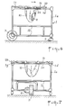
- Figures 6 and 7 show a side view and a rear view of a third embodiment of a walker.
- the self-propelled chassis 1, la, 1b, lc comprises an upper rectangular frame, formed by two longitudinal members Id, Ig and two cross members le.
- the nacelle 10 is suspended from a carriage 19 which is equipped with rollers 20 which roll on the two longitudinal members ld, Ig.
- a relative displacement sensor 21 is placed between the carriage and one of the cross members and it emits an electrical signal proportional to the relative longitudinal displacement of the carriage relative to its equilibrium position.
- the carriage is connected to the motor chassis by one or more springs 22 which tend to bring the carriage back to a stable equilibrium position.
- the springs 22 are intended to force the patient to do an effort to move the carriage, so that it is possible to adjust this effort and increase the return force of the springs according to the progress made by the patient.
- the springs can be replaced by equivalent return devices, for example elastic buffers or by captive gas struts.
- the chassis 1 comprises a single driving wheel 3 situated in the longitudinal axial plane which is driven by a motor 4 which is controlled by the signal delivered by the sensor 21 in the direction which cancels the relative movement of the carriage 19 relative to the chassis.
- the self-propelled chassis moves under the combined action of the thrust transmitted to it by the springs 22 and the action of the wheel 3.
- the sensor 21 can be any known linear displacement sensor, for example, a capacitive sensor or an inductive sensor comprising a movable core displaceable inside a double inductor coil, or a resistive sensor comprising a resistance and a cursor linked to the carriage which moves along the resistor or an optical sensor comprising a light source which illuminates a photoelectric receiver with an intensity which varies with distance, etc.
- the walkers according to the invention can easily be transformed into a passive self-propelled cart.
- the patient just has to lift their feet, grab the chassis with their hands and pull on their arms and the self-propelled chassis then advances in a continuous movement and transforms into a motorized wheelchair.
- the nacelle 10 can be replaced by other equivalent forms of support, such as for example a seat, a harness, a saddle, etc.
- the word nacelle is used in a general sense to designate any of these supports .
- the device according to FIG. 3 makes it possible to adjust the coefficient of proportionality between the relative movement of the platform support and the voltage delivered by the potentiometer. For this, it is' t to move the position of the joint head 14a of the rod 14 into the slot 15a of the slider.
- the coefficient of proportionality can also be varied electronically by modifying the gain of the amplifiers of the signals delivered by the sensors.
Abstract
L'invention a pour objet des déambulateurs actifs destinés à l'apprentissage et à la rééducation de la motricité. Un déambulateur selon l'invention comporte un châssis automoteur (1) monté sur des roues (2, 3) dont l'une au moins est motorisée. Il comporte une nacelle (10), qui est fixée à un support mobile (6) et dans laquelle prend place un patient dont les pieds touchent le sol. Le support mobile (6) est suspendu au châssis (1) par des bieliettes articulées (7) qui permettent un déplacement relatif du support par rapport au châssis dans le sens longitudinal. Un capteur (12) relie une biellette au châssis et émet un signal électrique proportionnel au déplacement longitudinal. Le moteur (4) qui entraîne la roue motrice (3) est incorporé dans une boucle d'asservissement commandée par le signal délivré par le capteur (12). Une application est la rééducation de la marche chez les individus ayant des troubles de la motricité.The subject of the invention is active walkers intended for learning and rehabilitating motor skills. A walker according to the invention comprises a self-propelled chassis (1) mounted on wheels (2, 3) of which at least one is motorized. It comprises a nacelle (10), which is fixed to a mobile support (6) and in which takes place a patient whose feet touch the ground. The mobile support (6) is suspended from the chassis (1) by articulated connecting rods (7) which allow relative movement of the support relative to the chassis in the longitudinal direction. A sensor (12) connects a link to the chassis and emits an electrical signal proportional to the longitudinal displacement. The motor (4) which drives the driving wheel (3) is incorporated in a servo loop controlled by the signal delivered by the sensor (12). One application is gait rehabilitation in individuals with motor impairment.
Description
L'invention a pour objet des dispositifs déambulateurs actifs destinés à l'éducation ou à la rééducation de la marche.The invention relates to active walker devices intended for education or for re-education of walking.
Le secteur technique de l'invention est celui de la construction des appareils automoteurs destinés à développer, à restaurer ou à relancer les facultés de locomotion des enfants ou des handicapés.The technical sector of the invention is that of the construction of self-propelled devices intended to develop, restore or revive the powers of locomotion of children or the disabled.
L'éducation ou la rééducation de la motricité peuvent être obtenus en plaçant un individu dans un milieu artificiel, par exemple dans l'eau d'une piscine, qui allège le poids et qui facilite les mouvements.Education or rehabilitation of motor skills can be obtained by placing an individual in an artificial environment, for example in the water of a swimming pool, which lightens the weight and which facilitates movements.
On utilise également des appareils d'exercice, par exemple des bicyclettes, au moyen desquelles le patient s'entraîne à développer et à réhabiliter certains muscles et certains éléments du système locomoteur ou des déambulateurs non motorisés sur lesquels le sujet prend appui et qu'il déplace avec lui. Ces appareils nécessitent de la force musculaire et un bon équilibre du sujet.Exercise machines, such as bicycles, are also used by which the patient trains to develop and rehabilitate certain muscles and elements of the locomotor system or non-motorized walkers on which the subject rests and which he move with him. These devices require muscular strength and a good balance of the subject.
On connaît également les fauteuils roulants ou les déambulateurs motorisés passifs qui facilitent les déplacements des handicapés entre les séances de rééducation, mais qui ne participent pas à l'apprentissage de la marche.There are also known wheelchairs or passive motorized walkers which facilitate the movement of the disabled between rehabilitation sessions, but who do not participate in learning to walk.
Un inconvénient des dispositifs et appareils d'exercice connus, réside dans le fait qu'ils ne sont utilisés que pendant la durée des séances de rééducation, c'est-à-dire pendant un temps limité et dans un environnement distinct de celui où vit habituellement le sujet, ce qui réduit leur efficacité. De plus, ils ne permettent pas au sujet d'accéder au vécu de la marche, c'est-à-dire à la sensation proprioceptive de la marche. Enfin, ils nécessitent une participation consciente et active du sujet. Dans le cas de jeunes enfants ayant des troubles de la motricité dus à des déficiences mentales, il n'est pas toujours possible d'obtenir leur participation active pendant les séances de rééducation.A disadvantage of known exercise devices and apparatuses resides in the fact that they are used only during the duration of the rehabilitation sessions, that is to say for a limited time and in an environment distinct from that in which lives usually the subject, which reduces their effectiveness. In addition, they do not allow the subject to access the experience of walking, that is to say the proprioceptive feeling of walking. Finally, they require a conscious and active participation of the subject. In the case of young children with motor impairment due to mental deficiencies, it is not always possible to obtain their active participation during the rehabilitation sessions.
Les déambulateurs motorisés passifs connus, qui sont destinés à des sujets qui disposent d'une très faible motricité, laissent ceux-ci entièrement inactifs,ce qui renforce leur passivité et leur immobilité.Known passive motorized walkers, which are intended for subjects who have very low motor skills, leave them entirely inactive, which reinforces their passivity and their immobility.
Un objectif de la présente invention est de procurer des . dispositifs déambulàteurs actifs qui remédient aux inconvénients des méthodes et appareils connus.It is an object of the present invention to provide. active walker devices which remedy the drawbacks of known methods and apparatus.
Un autre objectif de l'invention est de procurer des dispositifs déambulateurs actifs :
- - qui mettent en jeu tout ou partie du système locomoteur;
- - qui peuvent fonctionner dans le milieu de vie du sujet soit en milieu hospitalier, soit à domicile;
- - qui peuvent être utilisés de manière prolongée et continue sans fatiguer le sujet et qui amplifient et développent les plus faibles possibilités locomotrices de celui-ci;
- - qui permettent de graduer les forces d'appui au sol et le degré de participation active du sujet:
- - qui permettent de passer, de manière progressive, d'une fonction de rééducation active à une fonction de transport plus passive, ces deux fonctions pouvant être associées diversement.
- - which involve all or part of the locomotor system;
- - which can operate in the subject's living environment either in hospital or at home;
- - which can be used in a prolonged and continuous way without tiring the subject and which amplify and develop the weakest locomotor possibilities of this one;
- - which allow graduation of the ground support forces and the degree of active participation of the subject:
- - which make it possible to progressively move from an active rehabilitation function to a more passive transport function, these two functions being able to be combined in various ways.
Un autre objectif de l'invention est de procurer des dispositifs déambulateurs actifs qui permettent d'accélérer, chez des enfants retardés, l'apprentissage de la marche et le franchissement de cette étape dont tout le monde reconnaît l'importance et l'effet de seuil pour leur développement ultérieur.Another objective of the invention is to provide active walker devices which make it possible to accelerate, in retarded children, learning to walk and the crossing of this stage of which everyone recognizes the importance and the effect of threshold for their further development.
Les déambulateurs actifs selon l'invention comportent, de façon connue, un chassis automoteur monté sur des roues dont l'une au moins est une roue motrice, entraînée par un moteur, et il comporte également une nacelle dans laquelle un sujet prend place, qui comporte des orifices pour le passage des jambes et qui est supportée par le châssis à une hauteur telle que les pieds du sujet touchent le sol.The active walkers according to the invention comprise, in known manner, a self-propelled chassis mounted on wheels, at least one of which is a driving wheel, driven by a motor, and it also comprises a nacelle in which a subject takes place, which has holes for the passage of the legs and which is supported by the frame at a height such that the subject's feet touch the ground.
Les objectifs de l'invention sont atteints au moyen de déambulateurs qui sont caractérisés en ce que ladite nacelle est fixée sur un support mobile qui est relié audit châssis automoteur par des moyens de liaison qui lui permettent de se déplacer librement par rapport audit châssis dans au moins une direction, que ledit support mobile est relié audit châssis par au moins un capteur qui émet un signal électrique proportionnel à l'une des composantes du mouvement relatif dudit support par rapport audit châssis et qu'il comporte des boucles d'asservissement, qui relient chacun desdits capteurs à l'un desdits moteurs et qui commandent automatiquement lesdits moteurs pour déplacer ledit châssis d'un mouvement qui correspond, en direction e: en intersité, au mouvement relatif dudit .support par rapport audit t chéssis.The objectives of the invention are achieved by means of walkers which are characterized in that said nacelle is fixed on a mobile support which is connected to said self-propelled chassis by connecting means which allow it to move freely relative to said chassis in at at least one direction, that said movable support is connected to said chassis by at least one sensor which emits an electrical signal proportional to one of the components of the relative movement of said support with respect to said chassis and that it includes control loops, which connect each of said sensors to one of said motors and which automatically control said motors to move said chassis with a movement which corresponds, in direction e: in intersity, to the relative movement of said .support with respect to said t chéssis.
Selon un mode de réalisation préférentiel, le châssis automoteur a une forme générale rectangulaire et comporte quatre montants d'angles verticaux, ledit support mobile a églament une forme générale rectangulaire plus.petite dont les côtés sor intérieur à ceux dudit châssis et il est suspendu auxdits montants par quatre organes de suspension; l'extrémité inférieure de l'un au moins de ces organes de suspension est reliée audit châssis par un capteur de déplacement linéaire, qui émet un signal électrique proportionnel à la composante du déplacement relatif de ladite extrémité inférieure par rapport audit châssis qui est parallèle à l'axe longitudinal du châssis, ledit châssis comporte autant de roues motorisées que de capteurs, lesquelles roues sont entraînées par un groupe motoréducteur et chaque moteur est relié à l'un des capteurs par une boucle d'asservissement qui commande automatiquement ledit moteur dans le sens qui annule le signal émis par ledit capteur.According to a preferred embodiment, the self-propelled chassis has a generally rectangular shape and comprises four uprights of vertical angles, said movable support also has a generally rectangular shape plus.petite whose sides are internal those of said chassis and it is suspended from said uprights by four suspension members; the lower end of at least one of these suspension members is connected to said chassis by a linear displacement sensor, which emits an electrical signal proportional to the component of the relative displacement of said lower end relative to said chassis which is parallel to the longitudinal axis of the chassis, said chassis comprises as many motorized wheels as there are sensors, which wheels are driven by a geared motor group and each motor is connected to one of the sensors by a servo loop which automatically controls said motor in the direction which cancels the signal emitted by said sensor.
L'invention a pour résultat de nouveaux dispositifs déambula= teurs actifs qui permettent de corriger très efficacement les déficiences de la motricité chez les enfants ou chez les accidentés.The invention results in new active walker devices which make it possible to very effectively correct motor skills deficiencies in children or in accident victims.
Les expériences réalisées sur des prototypes ont montré que les déambulateurs selon l'invention facilitent très efficacement l'apprentissage ou la rééducation de la motricité. En effet le poids du corps est supporté par la nacelle ce qui soulage d'autant le patient. De plus, le support de nacelle qui est suspendu au châssis automoteur ou qui roule sans frottement sur celui-ci, se déplace à la moindre sollicitation du sujet et immédiatement le châssis automoteur suit sans demander aucun effort musculaire. Il en résulte que le patient voit ses moindres ébauches de mouvements suivies d'un déplacement, ce qui l'incite à continuer.Experiments carried out on prototypes have shown that the walkers according to the invention very effectively facilitate learning or rehabilitation of motor skills. Indeed the weight of the body is supported by the nacelle which relieves the patient as much. In addition, the platform support which is suspended from the self-propelled chassis or which rolls therefrom without friction, moves at the slightest request from the subject and immediately the self-propelled chassis follows without requiring any muscular effort. As a result, the patient sees his least drafts of movements followed by displacement, which prompts him to continue.
En particulier chez les enfants atteints de troubles 'de la motricité dus à une inhibition psychique, les déambulateurs actifs selon l'invention permettent de rétàblir la confiance de l'enfant qui prend conscience de ses possibilités et très rapidement l'inhibition est supprimée.In particular in children suffering from motor disturbances due to psychic inhibition, the active walkers according to the invention make it possible to restore the confidence of the child who becomes aware of his possibilities and very quickly the inhibition is eliminated.
Les déambulateurs selon l'invention comportent des moyens tels que des bielles, des lames de flexions, des ressorts, qui constituent une liaison mécanique plus ou moins rigide . entre le support mobile de la nacelle et le châssis automoteur. On peut faire varier le coefficient d'élasticité ou le module de cette liaison afin de doser progressivement les efforts musculaires demandés au patient à mesure qu'il fait des progrès.The walkers according to the invention comprise means such as connecting rods, bending blades, springs, which constitute a more or less rigid mechanical connection. between the mobile support of the nacelle and the self-propelled chassis. The coefficient of elasticity or the modulus of this connection can be varied in order to gradually dose the muscular efforts required of the patient as he progresses.
Parmi les applications possibles des déambulateurs selon l'invention, on citeïa :
- - l'accélération du franchissement de l'étape de la marche chez les enfants retardés qui a un effet de seuil pour le développement ultérieur;
- - l'accélération de la rééducation de la motricité après un traumatisme osseux ou musculaire chez l'enfant ou chez l'adulte;
- - l'amélioration de la restauration fonctionnelle de la motricité après des lésions nerveuses.
- - the acceleration of the crossing of the step of walking in retarded children which has a threshold effect for further development;
- - acceleration of motor skills rehabilitation after bone or muscle trauma in children or adults;
- - improving functional restoration of motor skills after nerve damage.
La description suivante se réfère aux dessins annexés qui représentent, sans aucun caractère limitatif, des exemples de réalisation de déambulateurs actifs selon l'invention.
- Les figures 1 et 2 sont une vue de côté et une vue de l'arrière d'un premier mode de.réalisation.
- La figure 3 est une vue partielle à plus grande échelle du capteur des figures 1 et 2.
- Les figures 4 et 5 représentent une vue de côté et une vue de l'arrière d'un deuxième mode de réalisation.
- Les figures 6 et-7 représentent une vue de côté et une vue de l'arrière d'un troisième mode de réalisation.
- Figures 1 and 2 are a side view and a rear view of a first mode de.réalisation.
- FIG. 3 is a partial view on a larger scale of the sensor of FIGS. 1 and 2.
- Figures 4 and 5 show a side view and a rear view of a second embodiment.
- Figures 6 and -7 show a side view and a rear view of a third embodiment.
Lès figures 1 et 2 représentent un déambulateur actif qui comporte un châssis 1, par exemple un châssis tubulaire de forme générale rectangulaire, qui est monté sur des roues 2 porteuses et autodirectrices, c'est-à-dire des roues qui sont montées sur un support pivotant autour d'un axe vertical, l'axe de la roue étant excentré par rapport audit axe vertical. Le châssis 1 comporte, en outre, une roue motrice 3; qui est placée dans l'axe du châssis. parallèle à la direction de la marche et dont l'axe est transversal au châssis. La roue motrice 3 est entraînée par un groupe motoréducteur 4 dont le moteur électrique est un moteur à double sens, alimenté par exemple par une batterie d'accumulateurs 5, portée par le châssis.Lès Figures 1 and 2 show an active walker which comprises a
Le châssis 1 est composé de quatre montants verticaux la, situés aux quatre angles et reliés entre eux par des longerons lb et par des traverses Ic...The
Un support mobile de nacelle 6, qui est par exemple un cadre tubulaire rectangulaire, plus petit que le châssis 1, est suspendu aux quatre montants la par quatre biellettes 7. Les biellettes 7 sont situées dans des plans verticaux, longitudinaux, c'est-à-dire parallèles au sens de la marche. L'extrémité supérieure de chaque biellette est articulée au châssis autour d'un axe horizontal 8 et l'extrémité inférieure de chaque biellette est articulée autour d'un axe horizontal 9. Les axes 8 et 9 sont transversaux, c'est-à-dire perpendiculaires à la direction de la marche et parallèles à l'axe de la roue motorisée 3.A
Une nacelle 10 est suspendue au cadre supérieur 6a du support 6. La nacelle 10 est par exemple une nacelle en toile, en forme de culotte, comportant deux orifices 11 pour le passage des jambes d'un patient qui prend place dans la nacelle. La hauteur du support de nacelle 6 est telle que les pieds du patient prennent appui sur le sol. Ainsi, la plus grande partie du poids du patient est supportée par la nacelle 10 et transféréeau sol par le support .6, les biellettes 7 et le châssis 1. Toutefois, grâce au contact de ses pieds avec le sol, le patient peut prendre un léger appui sur le sol et exercer sur la nacelle 10 une force qui tend à déplacer la nacelle par rapport au châssis 1 en faisant pivoter les quatre biellettes autour de leur axe 8 de suspension. L'une des biellettes est équipée d'un capteur 12 qui capte une des composantes du mouvement relatif du support 6 par rapport au châssis 1 et qui convertit analogiquement l'imtensité de cette composante en un signal électrique, par exemple ume tension, proportionnel à l'intensité de la composante mesurée.A
On précise que le mot mouvement est pris dans un sens général et le mot composante du mouvement désigne tout vecteur qui caractérise le mouvement relatif et qui peut être la composante dans une direction détermimée d'un déplacement linéaire ou angulaire, d'une vitesse, d'une force correspondant à une accélération, ou d'un couple.It is specified that the word movement is taken in a general sense and the word component of the movement indicates any vector which characterizes the relative movement and which can be the component in a determined direction of a linear or angular displacement, of a speed, d 'a force corresponding to an acceleration, or a couple.
Les figures 1 et 2 représentent un mode de réalisation le plus simple d'un déambulateur actif servant à stimuler la marche en ligne droite et dans lequel, du fait de la suspension du support 6 par les quatre biellettes 7, le mouvement relatif de la nacelle par rapport au châssis est un mouvement à un seul degré de liberté, dans une direction rectiligne parallèle à l'axe longitudinal du châssis.Figures 1 and 2 show a simplest embodiment of an active walker used to stimulate walking in a straight line and in which, due to the suspension of the
La figure 3 représente une vue en élévation du capteur 12. Celui-ci est composé d'un potentiomètre rotatif 13 qui est fixé au châssis 1. Il comporte une biellette 14 qui relie l'articulation 9 au curseur 15 du potentiomètre qui comporte une encoche 15a, dans laquelle pénètre une extrémité 14a de la biellette 14. Ainsi le mouvement relatif du châssis 6 par rapport au châssis 1 est transmis par la biellette 14 au curseur rotatif 15 et la tension émise par le potentiomètre varie, positivement ou négativement,autour d'une valeur de référence proportionnellement à l'angle de pivotement de la biellette 7. Cette tension est amplifiée.FIG. 3 represents an elevation view of the
Un dispositif d'asservissement reçoit la tension amplifiée et met automatiquement en marche le moteur 4 dans le sens qui annule l'écart entre la tension émise et la tension de référence, ce qui correspond à un déplacement absolu du châssis automoteur 1 par rapport au sol de même direction et de même longueur que le déplacement relatif de la nacelle par rapport au châssis.A servo device receives the amplified voltage and automatically starts the
Dans cet exemple où le déplacement relatif de La nacelle par rapport au châssis est un déplacement unidirectionnel, le châssis automoteur 1 est équipé d'une seule roue motorisée située dans l'axe longitudinal qui déplace le châssis automoteur dans une seule direction.In this example where the relative movement of the nacelle relative to the chassis is a unidirectional movement, the self-propelled
On comprend que, du fait que le support de nacelle 6 est suspendu par quatre biellettes au châssis 1, la moindre poussée que le patient exercera sur le sol avec ses pieds suffit à déplacer la nacelle.It is understood that, because the
Les articulations 8 et 9 sont des articulations sans frottement, par exemple des roulements. La roue motrice déplace aussitôt le châssis automoteur d'une longueur équivalente sans que le patient n'ait à dépenser aucune énergie pour obtenir ce déplacement. De et fait, les efforts du patient sont démultipliés et celui-ci, qui perçoit le résultat de ses efforts est vivement incité à persévérer, d'où un effet d'encouragement à l'effort.The
Le dispositif selon les figures 1 et 2 permet d'ajuster l'effort demandé au patient à mesure qu'il progresse. En effet, lorsque le support de nacelle 6 quitte sa position d'équilibre stable, le poids P du patient exerce sur les biellettes un couple qui rappelle les biellettes vers la position d'équilibre et qui est égal à P.ℓsinα, ℓ étant la longueur de la biellette et a l'angle de rotation. En jouant sur la longueur des biellettes 7, on peut faire varier le couple de rappel et obliger le patient,à mesure qu'il progresse, à faire un effort de plus en plus grand, pour obtenir un même déplacement relatif.The device according to FIGS. 1 and 2 makes it possible to adjust the effort required of the patient as he progresses. In fact, when the
Lorsque le patient est assis dans la nacelle 10, ses mains se trouvent placées sensiblement à la hauteur du cadre supéricur 6 auquel la nacelle est suspendue. Ce cadre 6a se trouve placé au dessus de l'extrémité supérieure des montants 1 et suffisamment éloigné de ceux-ci pour que le patient ne puisse atteindre les montants avec ses mains et exercer une traction qui entraînerait un déplacement relatif de la nacelle par rapport au châssis et une liaison entre ceux-ci, de telle sorte que le chariot automoteur 1 se déplacerait d'un mouvement continu sans que le patient n'ait à exercer aucun effort avec ses pieds. Le chariot se comporterait alors comme un chariot automoteur passif.When the patient is seated in the
Les figures 4 et 5 représentent un autre mode de réalisation. Les parties homologues à celles des figures 1 et 2 sont représentées par les mêmes repères.Figures 4 and 5 show another embodiment. The parts homologous to those of FIGS. 1 and 2 are represented by the same references.
La différence réside dans le mode de réalisation de la suspension du support 6 et des capteurs de mouvement relatif du support 6 par rapport au châssis automoteur 1.The difference lies in the embodiment of the suspension of the
Dans ce mode de réalisation, le support de nacelle 6 est suspendu aux quatre montants la par des suspentes flexibles 16 qui sont par exemple des lames flexibles situées dans des plans transversaux, de telle sorte que lorsque le support 6 exerce un effort en direction longitudinale sur les lames 16, celles-ci fléchissent dans le sens longitudinal.In this embodiment, the
Des jauges de contrainte 17, du type jauge d'extensométrie, sont collées sur les lames flexibles 16 et elles émettent une ren- sion qui est proportionnelle à la flexion des lames et donc à la force qui est exercé sur elles. Selon un montage bien connu, on colle une paire de jauges d'extensométrie 17 sur chaque face de la lame et on monte celles-ci dans les quatre côtés d'un pont de résistances, les deux lames placées sur une même face étant montées en série, et le' courant qui circule dans la diagonale du pont est proportionnel à la flexion de la lame.Strain gauges 17, of the strain gauge type, are bonded to the
Le signal électrique qui circule dans la diagonale du pont est amplifié et il commande automatiquement la mise en route du moteur 4 dans le sens qui annule le signal.The electric signal which circulates in the diagonal of the bridge is amplified and it automatically controls the starting of the
Le mode de réalisation selon les figures 4 et 5 est un déambulateur actif ayant deux degrés de liberté, c'est-à-dire un déambulateur qui permet au patient de se déplacer dans une direc- .tion oblique en pivotant.The embodiment according to Figures 4 and 5 is an active walker having two degrees of freedom, that is to say a walker which allows the patient to move in an oblique direction by pivoting.
Dans ce cas, deux des suspentes avant ou arrière, par exemple les deux suspentes avant sont des fils (18d, 18g) ou des lames flexibles chantournées qui permettent une liberté de mouvement du support de nacelle par rapport au châssis dans toutes les directions. Les deux autres suspentes, c'est-à-dire les suspentes arrière sont des lames de flexion 16d, 16g, qui sont équipées chacune d'un capteur de déplacement 17d, 18g et le châssis comporte deux roues motorisées 3d, 3g situées à l'arrière et symétriques par rapport au plan de symétrie longitudinal. Le moteur 4d, 4g commandant chaque roue est asservi respectivement au signal électrique délivré par le capteur situé du même côté.In this case, two of the front or rear lines, for example the two front lines, are wires (18d, 18g) or flexible scalloped blades which allow freedom of movement of the nacelle support relative to the chassis in all directions. The other two lines, i.e. the rear lines are bending
Le pivotement du support de nacelle par rapport au châssis entraîne une différence dans les flexions des deux lames 16d, 16g portant les capteurs et cette différence se retrouve dans les progressions des deux roues 3d, 3g, de sorte que le châssis avance en tournant sur lui-même d'un angle égal à l'angle de pivotement du support de nacelle et,en fin de mouvement,le châssis se retrouve aligné avec le support de nacelle et il a avancé dans la même direction que celui-ci et de la même longueur.The pivoting of the nacelle support relative to the chassis causes a difference in the flexions of the two
Dans le mode de réalisation selon les figures 4 et 5, lorsque le support de nacelle se déplace, les lames flexibles 16 exercent sur lui une poussée qui tend à le ramener à la position d'équilibre et le patient doit exercer un effort pour vaincre cette poussée. En faisant varier la longueur des lames et leur flexibilité, par exemple en juxtaposant plusieurs lames de flexion, on peut doser l'effort demandé au patient pour obtenir un même déplacement, de sorte qu'il est possible d'augmenter cet effort à mesure que le patient progresse.In the embodiment according to FIGS. 4 and 5, when the nacelle support moves, the
Les figures 6 et 7 représentent une vue latérale et une vue de l'arrière d'un troisième mode de réalisation d'un déambulateur.Figures 6 and 7 show a side view and a rear view of a third embodiment of a walker.
Dans ce mode de réalisation, le châssis automoteur 1, la, 1b, lc comporte un cadre rectangulaire supérieur, formé de deux longerons Id, Ig et de deux traverses le. La nacelle 10 est suspendue à un chariot 19 qui est équipé de galets 20 qui roulent sur les deux longerons ld, Ig.In this embodiment, the self-propelled
Un capteur de déplacement relatif 21 est placé entre le chariot et l'une des traverses le et il émet un signal électrique proportionnel au déplacement longitudinal relatif du chariot par rap port à sa position d'équilibre. Le chariot est relié au.châss acomo- teur par un ou plusieurs ressorts 22 qui tendent à ramener le chariot vers une position d'équilibre stable.A
Les ressorts 22 ont pour but d'obliger le.patient à faire un effort pour déplacer le chariot, de sorte qu'il est possible de régler cet effort et d'augmenter la force de rappel des ressorts en fonction des progrès réalisés par le patient. Les ressorts peuvent être remplacés par des dispositifs de rappel équivalents,par exemple des tampons élastiques ou par des vérins à gaz prisonnier.The
Le châssis 1 comporte une seule roue motrice 3 située dans le plan axial longitudinal qui est entraînée par un moteur 4 qui est commandé par le signal délivré par le capteur 21 dans le sens qui annule le déplacement relatif du chariot 19 par rapport au châssis.The
Dans cet exemple, le châssis automoteur se déplace sous l'action combinée de la poussée qui lui est transmise par les ressorts 22 et de l'action de la roue 3. Plus on raidit les ressorts 22, plus l'effort dû au patient intervient dans le déplacement du châssis automoteur.In this example, the self-propelled chassis moves under the combined action of the thrust transmitted to it by the
Le capteur 21 peut être n'importe quel capteur de déplacement linéaire connu, par exemple, un capteur capacitif ou un capteur inductif comportant un noyau mobile déplaçable à l'intérieur d'une double bobine de self, ou un capteur résistif comportant une résistance et un curseur lié au chariot qui se déplace le long de la résistance ou un capteur optique comportant une source lumineuse qui éclaire un récepteur photo-électrique avec une intensité qui varie avec la distance, etc....The
Les déambulateurs selon l'invention peuvent être transfor- mésfacilement en chariot automoteur passif. Il suffit que le patient lève les pieds, qu'il attrape le châssis avec ses mains et qu'il tire sur ses bras et le châssis automoteur avance alors dans un mouvement continu et se transforme en fauteuil roulant motorisé.The walkers according to the invention can easily be transformed into a passive self-propelled cart. The patient just has to lift their feet, grab the chassis with their hands and pull on their arms and the self-propelled chassis then advances in a continuous movement and transforms into a motorized wheelchair.
La nacelle 10 peut être remplacée par d'autres formes de support équivalentes, telles que par exemple un siège, un harnais, une selle etc.... Le mot nacelle est utilisé dans un sens général pour désigner n'importe lequel de ces supports.The
Le dispositif selon la figure 3 permet de régler le coefficient de proportionnalité entre le déplacement relatif du support de nacelle et la tension délivrée par le potentiomètre. Pour cela, il se 't de déplacer la position de l'articulation 14a de la tête de biellette 14 dans la fente 15a du curseur.The device according to FIG. 3 makes it possible to adjust the coefficient of proportionality between the relative movement of the platform support and the voltage delivered by the potentiometer. For this, it is' t to move the position of the joint head 14a of the
Dans tous les modes de réalisation, on peut également faire varier le coefficient de proportionnalité électroniquement en modifiant le gain des amplificateurs des signaux délivrés par les capteurs.In all the embodiments, the coefficient of proportionality can also be varied electronically by modifying the gain of the amplifiers of the signals delivered by the sensors.
Claims (8)
Applications Claiming Priority (2)
| Application Number | Priority Date | Filing Date | Title |
|---|---|---|---|
| FR8203368A FR2522265B1 (en) | 1982-02-26 | 1982-02-26 | ACTIVE DEAMBULATOR DEVICE |
| FR8203368 | 1982-02-26 |
Publications (2)
| Publication Number | Publication Date |
|---|---|
| EP0088035A1 true EP0088035A1 (en) | 1983-09-07 |
| EP0088035B1 EP0088035B1 (en) | 1985-12-11 |
Family
ID=9271461
Family Applications (1)
| Application Number | Title | Priority Date | Filing Date |
|---|---|---|---|
| EP83430006A Expired EP0088035B1 (en) | 1982-02-26 | 1983-02-24 | Motorized walking-aid |
Country Status (4)
| Country | Link |
|---|---|
| US (1) | US4463817A (en) |
| EP (1) | EP0088035B1 (en) |
| DE (1) | DE3361454D1 (en) |
| FR (1) | FR2522265B1 (en) |
Cited By (3)
| Publication number | Priority date | Publication date | Assignee | Title |
|---|---|---|---|---|
| GB2228459A (en) * | 1989-01-31 | 1990-08-29 | Edward John Reed | Motorised walking aid |
| EP0578884A1 (en) * | 1991-04-09 | 1994-01-19 | Eugene P. Rodenborn | Motorized walker |
| US9375380B2 (en) | 2007-05-11 | 2016-06-28 | Rowanwood Ip Inc. | Mobility assistance device |
Families Citing this family (17)
| Publication number | Priority date | Publication date | Assignee | Title |
|---|---|---|---|---|
| US4776415A (en) * | 1987-07-13 | 1988-10-11 | Brice Michael L | Safety control for baby's walker |
| US5390753A (en) * | 1991-01-15 | 1995-02-21 | Parker; Bruce H. | Personal walker with powered wheels |
| US5152730A (en) * | 1991-06-04 | 1992-10-06 | Hoffman Roger E | Handless walking aid for preventing falls from loss of balance |
| US5167597A (en) * | 1991-10-01 | 1992-12-01 | George David | Wheeled walker treatment method |
| US5524720A (en) * | 1994-08-19 | 1996-06-11 | Lathrop; John | Powered walker having integrated parallel bars |
| JP2000501964A (en) | 1995-12-14 | 2000-02-22 | アルティメイト サポート システムズ,インコーポレイテッド | Method and system for intensive primary user support in a support aid device |
| US7540342B1 (en) * | 2002-03-21 | 2009-06-02 | Robert John Ein | Virtual walker apparatus |
| US20040063550A1 (en) * | 2002-07-19 | 2004-04-01 | Harris Robert D. | Mobile body suspension exercise device |
| GB0616310D0 (en) * | 2006-08-16 | 2006-09-27 | Pocock Rosemary T I | Movement limiting apparatus |
| DE102007051864A1 (en) * | 2007-10-30 | 2009-05-07 | Siemens Ag | Moving surface used as a seating surface of a wheelchair or a lying surface of an operating table comprises a sensor arrangement for detecting a force transferring by the hand of the operator directly onto the surface and a drive unit |
| TWI377057B (en) * | 2010-01-07 | 2012-11-21 | Univ Nat Yang Ming | Walking assistance device with detection members and application method thereof |
| US9510990B2 (en) * | 2010-08-23 | 2016-12-06 | Michael J. Workman | Gait training apparatuses, attachments for gait training and related methods |
| US8714593B2 (en) * | 2011-08-24 | 2014-05-06 | Robert Bonanno | Human powered vehicle with unpowered wheels |
| CN103142390B (en) * | 2013-02-04 | 2014-10-01 | 国家康复辅具研究中心 | Walking aid for handicapped children |
| WO2018231653A1 (en) * | 2017-06-14 | 2018-12-20 | Drossman Andrew Michael | Self-balancing personal vehicle with suspended harness assembly |
| US10667980B2 (en) * | 2018-03-28 | 2020-06-02 | The Board Of Trustees Of The University Of Alabama | Motorized robotic walker guided by an image processing system for human walking assistance |
| US11396314B2 (en) | 2018-03-28 | 2022-07-26 | The Board Of Trustees Of The University Of Alabama | Motorized robotic walker guided by an image processing system for human walking assistance |
Citations (3)
| Publication number | Priority date | Publication date | Assignee | Title |
|---|---|---|---|---|
| CH339715A (en) * | 1957-08-02 | 1959-07-15 | Savary Emile | Baby support device |
| BE659563A (en) * | 1965-01-23 | 1965-05-28 | ||
| US3872945A (en) * | 1974-02-11 | 1975-03-25 | Falcon Research And Dev Co | Motorized walker |
Family Cites Families (5)
| Publication number | Priority date | Publication date | Assignee | Title |
|---|---|---|---|---|
| US2210269A (en) * | 1938-02-01 | 1940-08-06 | Byron M Taylor | Means to aid in regaining normal body locomotion |
| US3504927A (en) * | 1968-04-10 | 1970-04-07 | Showa Motsuku Kaisha | Baby walker |
| US3621819A (en) * | 1970-07-02 | 1971-11-23 | Pleas J Hooper | Cow walker |
| US3992023A (en) * | 1975-04-07 | 1976-11-16 | Moorer Donald K | Baby crawler |
| US4280578A (en) * | 1979-02-21 | 1981-07-28 | Margaret P. Roberts | Motorized walker for the disabled |
-
1982
- 1982-02-26 FR FR8203368A patent/FR2522265B1/en not_active Expired
-
1983
- 1983-02-24 EP EP83430006A patent/EP0088035B1/en not_active Expired
- 1983-02-24 DE DE8383430006T patent/DE3361454D1/en not_active Expired
- 1983-02-25 US US06/469,904 patent/US4463817A/en not_active Expired - Fee Related
Patent Citations (3)
| Publication number | Priority date | Publication date | Assignee | Title |
|---|---|---|---|---|
| CH339715A (en) * | 1957-08-02 | 1959-07-15 | Savary Emile | Baby support device |
| BE659563A (en) * | 1965-01-23 | 1965-05-28 | ||
| US3872945A (en) * | 1974-02-11 | 1975-03-25 | Falcon Research And Dev Co | Motorized walker |
Cited By (3)
| Publication number | Priority date | Publication date | Assignee | Title |
|---|---|---|---|---|
| GB2228459A (en) * | 1989-01-31 | 1990-08-29 | Edward John Reed | Motorised walking aid |
| EP0578884A1 (en) * | 1991-04-09 | 1994-01-19 | Eugene P. Rodenborn | Motorized walker |
| US9375380B2 (en) | 2007-05-11 | 2016-06-28 | Rowanwood Ip Inc. | Mobility assistance device |
Also Published As
| Publication number | Publication date |
|---|---|
| FR2522265B1 (en) | 1984-06-01 |
| FR2522265A1 (en) | 1983-09-02 |
| US4463817A (en) | 1984-08-07 |
| DE3361454D1 (en) | 1986-01-23 |
| EP0088035B1 (en) | 1985-12-11 |
Similar Documents
| Publication | Publication Date | Title |
|---|---|---|
| EP0088035B1 (en) | Motorized walking-aid | |
| US5732964A (en) | User-propelled steerable apparatus | |
| JP3697638B2 (en) | Wheelchair for transporting or assisting handicapped persons | |
| WO2002092164A2 (en) | Therapeutic and/or training device for a person's lower limbs | |
| US20120216347A1 (en) | Reciprocating Rocking Device | |
| EP2672944B1 (en) | Device for autonomous retraining in walking | |
| WO2005117799A1 (en) | Device for the reeducation of motory deficiencies, particularly deficiencies when walking, in patients | |
| WO2016166442A1 (en) | Movement assistance device | |
| JP2012223527A (en) | Three-wheel foot-pedaled wheelchair | |
| ES2185248T3 (en) | DEVICE FOR UPLOADING MOTORIZED DRIVING STAIRS. | |
| US20170239110A1 (en) | Mobile Chair Apparatus Comprising Foot Pedals | |
| Rajasekar et al. | Design and fabrication of staircase climbing wheelchair | |
| US9757288B1 (en) | Mobile chair apparatus comprising foot pedals | |
| WO1998037850A1 (en) | Device for producing continuous passive motion | |
| WO1997028775A1 (en) | Hands-free leg/motor powered vehicle | |
| KR100978386B1 (en) | Wheelchair for handicapped child | |
| GB2307453A (en) | "Hands free" collapsible wheelchair with motor assistance, skid steer, and seat raising ram | |
| JP2003339780A (en) | Front drive type wheelchair | |
| EP3518858B1 (en) | Mobile assistance robot comprising at least one pivoting bearing system | |
| US7510214B1 (en) | Method and system for assisting individual ambulation | |
| Shriwaskar et al. | Synthesis, Modeling, Analysis and Simulation of stair climbing mechanism | |
| FR2737993A1 (en) | Three wheeled baby trotter | |
| RU1803084C (en) | Invalid carriage | |
| US2495968A (en) | Invalid equipment | |
| EP4154859A1 (en) | Medical apparatus for assisting patient to stand, control unit and control method therefor |
Legal Events
| Date | Code | Title | Description |
|---|---|---|---|
| PUAI | Public reference made under article 153(3) epc to a published international application that has entered the european phase |
Free format text: ORIGINAL CODE: 0009012 |
|
| AK | Designated contracting states |
Designated state(s): BE CH DE GB IT LI SE |
|
| 17P | Request for examination filed |
Effective date: 19831010 |
|
| GRAA | (expected) grant |
Free format text: ORIGINAL CODE: 0009210 |
|
| AK | Designated contracting states |
Designated state(s): BE CH DE GB IT LI SE |
|
| ITF | It: translation for a ep patent filed |
Owner name: JACOBACCI & PERANI S.P.A. |
|
| REF | Corresponds to: |
Ref document number: 3361454 Country of ref document: DE Date of ref document: 19860123 |
|
| PLBE | No opposition filed within time limit |
Free format text: ORIGINAL CODE: 0009261 |
|
| STAA | Information on the status of an ep patent application or granted ep patent |
Free format text: STATUS: NO OPPOSITION FILED WITHIN TIME LIMIT |
|
| 26N | No opposition filed | ||
| PG25 | Lapsed in a contracting state [announced via postgrant information from national office to epo] |
Ref country code: SE Effective date: 19870225 |
|
| PG25 | Lapsed in a contracting state [announced via postgrant information from national office to epo] |
Ref country code: LI Effective date: 19870228 Ref country code: CH Effective date: 19870228 |
|
| BERE | Be: lapsed |
Owner name: INSTITUT NATIONAL DE LA SANTE ET DE LA RECHERCHE M Effective date: 19870228 |
|
| GBPC | Gb: european patent ceased through non-payment of renewal fee | ||
| REG | Reference to a national code |
Ref country code: CH Ref legal event code: PL |
|
| PG25 | Lapsed in a contracting state [announced via postgrant information from national office to epo] |
Ref country code: DE Effective date: 19871103 |
|
| PG25 | Lapsed in a contracting state [announced via postgrant information from national office to epo] |
Ref country code: GB Effective date: 19881122 |
|
| PG25 | Lapsed in a contracting state [announced via postgrant information from national office to epo] |
Ref country code: BE Effective date: 19890228 |
|
| EUG | Se: european patent has lapsed |
Ref document number: 83430006.3 Effective date: 19880215 |