EP0087862B1 - Process for converting methanol into gasoline with enhanced gasoline yield - Google Patents
Process for converting methanol into gasoline with enhanced gasoline yield Download PDFInfo
- Publication number
- EP0087862B1 EP0087862B1 EP83300614A EP83300614A EP0087862B1 EP 0087862 B1 EP0087862 B1 EP 0087862B1 EP 83300614 A EP83300614 A EP 83300614A EP 83300614 A EP83300614 A EP 83300614A EP 0087862 B1 EP0087862 B1 EP 0087862B1
- Authority
- EP
- European Patent Office
- Prior art keywords
- methanol
- reactor
- catalyst
- gasoline
- conversion
- Prior art date
- Legal status (The legal status is an assumption and is not a legal conclusion. Google has not performed a legal analysis and makes no representation as to the accuracy of the status listed.)
- Expired
Links
Images
Classifications
-
- C—CHEMISTRY; METALLURGY
- C10—PETROLEUM, GAS OR COKE INDUSTRIES; TECHNICAL GASES CONTAINING CARBON MONOXIDE; FUELS; LUBRICANTS; PEAT
- C10G—CRACKING HYDROCARBON OILS; PRODUCTION OF LIQUID HYDROCARBON MIXTURES, e.g. BY DESTRUCTIVE HYDROGENATION, OLIGOMERISATION, POLYMERISATION; RECOVERY OF HYDROCARBON OILS FROM OIL-SHALE, OIL-SAND, OR GASES; REFINING MIXTURES MAINLY CONSISTING OF HYDROCARBONS; REFORMING OF NAPHTHA; MINERAL WAXES
- C10G3/00—Production of liquid hydrocarbon mixtures from oxygen-containing organic materials, e.g. fatty oils, fatty acids
- C10G3/42—Catalytic treatment
- C10G3/44—Catalytic treatment characterised by the catalyst used
- C10G3/48—Catalytic treatment characterised by the catalyst used further characterised by the catalyst support
- C10G3/49—Catalytic treatment characterised by the catalyst used further characterised by the catalyst support containing crystalline aluminosilicates, e.g. molecular sieves
-
- C—CHEMISTRY; METALLURGY
- C10—PETROLEUM, GAS OR COKE INDUSTRIES; TECHNICAL GASES CONTAINING CARBON MONOXIDE; FUELS; LUBRICANTS; PEAT
- C10G—CRACKING HYDROCARBON OILS; PRODUCTION OF LIQUID HYDROCARBON MIXTURES, e.g. BY DESTRUCTIVE HYDROGENATION, OLIGOMERISATION, POLYMERISATION; RECOVERY OF HYDROCARBON OILS FROM OIL-SHALE, OIL-SAND, OR GASES; REFINING MIXTURES MAINLY CONSISTING OF HYDROCARBONS; REFORMING OF NAPHTHA; MINERAL WAXES
- C10G2400/00—Products obtained by processes covered by groups C10G9/00 - C10G69/14
- C10G2400/02—Gasoline
-
- Y—GENERAL TAGGING OF NEW TECHNOLOGICAL DEVELOPMENTS; GENERAL TAGGING OF CROSS-SECTIONAL TECHNOLOGIES SPANNING OVER SEVERAL SECTIONS OF THE IPC; TECHNICAL SUBJECTS COVERED BY FORMER USPC CROSS-REFERENCE ART COLLECTIONS [XRACs] AND DIGESTS
- Y02—TECHNOLOGIES OR APPLICATIONS FOR MITIGATION OR ADAPTATION AGAINST CLIMATE CHANGE
- Y02P—CLIMATE CHANGE MITIGATION TECHNOLOGIES IN THE PRODUCTION OR PROCESSING OF GOODS
- Y02P30/00—Technologies relating to oil refining and petrochemical industry
- Y02P30/20—Technologies relating to oil refining and petrochemical industry using bio-feedstock
Definitions
- This invention relates to the conversion of methanol into gasoline boiling-range hydrocarbons and, more particularly, to maximizing gasoline production and minimizing catalyst deactivation in such a process.
- a conventional methanol-to-gasoline system as disclosed in United States Patent 3,928,483 consists of two or more reactors in series. Generally, in the condensation reactor stage methanol is passed over a condensation catalyst to produce aliphatic dehydration products and water. In the conversion stage a portion of the reaction products of the first stage is contacted with a crystalline aluminosilicate zeolite catalyst to convert those products into gasoline boiling-range hydrocarbons.
- United States Patent 3,931,349 discloses a two- stage process for converting methanol into gasoline where the exothermic temperature rise in the first stage is catalytically restricted and a heat-dissipating diluent is employed in the second stage.
- United States Patent 3,998,899 shows a process for passing methanol through a plurality of catalyst contact zones which are temperature restrained in response to catalyst activity and selectivity.
- Patent 4,083,889 shows a method for converting methanol into ethylene in the presence of steam and a ZSM-5 catalyst at a temperature of about 315 to about 400°C.
- United States Patent 4,035,430 discloses a method of converting methanol into gasoline boiling-range products in a plurality of sequential catalyst beds.
- One catalyst bed contains calcined alumina which dehydrates the methanol to produce dimethyl ether together with unconverted methanol and water.
- Dimethyl ether is then passed through a second series of catalyst contact zones comprising a plurality of catalyst beds in a single reactor.
- United States Patent 4,049,734 disclosed a two- step process for methanol conversion where synthesis gas is converted in a first stage to a product comprising methanol which is then converted into an aromatic gasoline product over a zeolite catalyst at a temperaure of about 260 to 650°C.
- United States Patent 4,058,576 discloses a multiple-stage catalyst process for converting methanol into olefins and/or gasoline boiling-range components.
- the reaction stages proceed through methanol conversion into dimethyl ether, ether conversion into olefins, and conversion of olefins into gasoline boiling-range components.
- United States Patent 4,138,442 discloses a process where methanol is reacted with a zeolite catalyst to a product which is resolved into a high octane gasoline fraction and other products.
- United States Patent 4,263,141 discloses a methanol-to-gasoline process in which the methanol is catalytically converted into gasoline hydrocarbons. The reaction takes place over known zeolite catalysts and the gasoline synthesis stage may consist of one or more tubular reactors.
- the present invention seeks to provide an improved process for the conversion of methanol into gasoline in which the downstream portion of the catalyst bed is not prematurely and permanently deactivated by steam.
- the advantages of such a process are particularly apparent from an economic point of view; by preventing the catalyst from becoming prematurely deactivated, the reactor will operate far more efficiently and economically and reactor shut-down rate will be drastically reduced as will the man-hours required in replacing the permanently deactivated catalyst.
- a process for the conversion of methanol into gasoline boiling-range components which com- . prises dehydrating a methanol feed in a first stage to obtain a dimethyl ether-containing product and catalytically converting the dimethyl ether-containing product in a second stage into gasoline boiling-range components, characterized in that the second stage is carried out in a plurality of reactors so arranged that each downstream reactor can be operatively connected in series to the upstream reactor(s) once the catalyst in the immediately preceding upstream reactor has attained a predetermined degree of deactivation.
- the invention improves upon the known methanol-to-gasoline process by dividing the conversion reactor catalyst bed into a series of smaller beds such that the conversion can be accomplished completely in the first reactor thereby preventing premature deactivation of the catalyst beds downstream of the point at which the reaction products are removed.
- the gasoline synthesis zones are so arranged that gasoline production is maximized and catalyst deactivation is minimized.
- the cooling of the reactor is advantageously accomplished by recirculating light hydrocarbon product gas to the reactor inlet.
- the volume of catalyst is suitably the same as in a conventional methanol-to-gasoline process.
- the present system can incorporate more than two conversion reactors in series.
- the methanol feed used in the process of the invention will generally consist largely of methanol but may contain one or more other simple alcohols and/or higher alcohols.
- the feed may include methanol, ethanol, propanol and isopropanol.
- Such a mixture of alcohols generally results from prior gasification and methanol synthesis steps which may be integrated with the methanol-to-gasoline process. It is to be understood, however, that no more than trace amounts of the synthesis gas product of a prior gasification step should be fed to the methanol-to-gasoline process of the invention.
- the methanol-to-gasoline process of the invention is carried out in a system that consists of at least three reactors in series.
- the first reactor the dehydration reactor
- methanol is converted to an equilibrium mixture of methanol, dimethyl ether and water.
- These products are then generally mixed with light hydrocarbon recycle gas and fed into the second and third reactors (the conversion reactor), where the combined feed is converted into gasoline boiling-range hydrocarbons.
- the alcohol reactant is contacted with a condensation catalyst to produce water and predominantly aliphatic organic intermediates.
- the preferred alcohol reactants to this first stage are ethanol and methanol. Particularly preferred are charges comprising a substantial fraction, i.e. more than 25 weight percent, of methanol.
- the condensation catalyst may be any catalyst which produces intermolecular dehydration of the alcohol reactant to form an aliphatic product of higher carbon-to-oxygen ratio than the feed. While the dehydration reaction by itself is generally run with alumina compositions such as gamma alumina, other known acidic catalysts are very effective for the conversion.
- Such catalysts include for example, liquid acids such as sulfuric and phosphoric acids, and solid inorganic and organic acidic catalysts such as phosphoric acids supported by kieselguhr, high surface area silica- alumina, acidic alumina, acid-treated clays, bauxites, and polystyrene sulfonic acids of the ionexchange type including the macro-reticular variety.
- liquid acids such as sulfuric and phosphoric acids
- solid inorganic and organic acidic catalysts such as phosphoric acids supported by kieselguhr, high surface area silica- alumina, acidic alumina, acid-treated clays, bauxites, and polystyrene sulfonic acids of the ionexchange type including the macro-reticular variety.
- solid acidic catalysts for the purpose of this invention, it is preferred to use solid acidic catalysts.
- the first stage reaction effluent mixture has a temperature of 370 to 430°C. This effluent is then mixed with C 5 and lighter hydrocarbons prior to its passage into the second stage catalytic zone.
- the second stage catalytic conversion operation of the invention is particularly restricted to converting the first stage effluent mixture comprising methanol, dimethyl ether and water into an olefin-rich product material and/or a product rich in gasoline boiling-range components.
- the operation is highly exothermic and occurs rapidly in the presence of selected crystalline zeolites and particularly catalysts comprising ZSM-5 type crystalline zeolites.
- ZSM-5 type crystalline zeolites are disclosed in United States Patents 3,702,886 and 4,100,262.
- the effluent is mixed with a diluent material, preferably the C 5 and lighter hydrocarbons, in an amount sufficient to act as a heat carrier and provide a mixture at a temperature of about 315 to 400°C which is a desired inlet temperature for completing the conversion of the effluent as well as the unconverted methanol by contact with the crystalline zeolite ZSM-5 catalyst.
- a diluent material preferably the C 5 and lighter hydrocarbons
- conversion of the first stage effluent mixture is accomplished in fixed bed catalyst-containing reactors which comprise two or more reactor beds or units arranged in series.
- each reactor bed depends directly on the number of units incorporated into the conversion reactor. For example, if two reactor beds make up the conversion reactor system, then each bed is approximately one-half the size of a conventional reactor bed. In addition to the size of the individual reactor beds, the amount of catalyst in each bed is directly related to the number of units in the reactor system. As in the example above, each bed of a two reactor bed system will contain approximately one-half of the total amount of the catalyst incorporated into the system. Thus, the total amount of catalyst in the multi-bed conversion reactor is substantially equal to the amount of catalyst in the conventional single bed reactor system.
- a particular aspect of this invention lies in the sequential arrangement of the individual reactor beds.
- Process piping initially isolates the other reactor bed(s) from the first reactor bed of the second stage allowing the first stage effluent mixture to ehterthe first reactor bed of the second stage.
- the effluent mixture is then allowed to be fully converted in a conventional manner in the first reactor bed of the second stage until such time as the catalyst has deactivated to the extent that unconverted methanol begins to exit from that first conversion reactor bed.
- the process piping connecting the reactor beds is altered to allow the effluent mixture to pass through the initial reactor bed and enter a subsequent reactor bed. In this manner the effluent mixture enters the initial reactor bed where it is partially converted, and the partially converted effluent then enters a subsequent reactor bed for full conversion until, as described above, unconverted methanol is discovered exiting the second conversion reactor bed.
- the effluent from the second stage conversion may be cooled by indirect heat exchange to a temperature from 25 to 95°C.
- the cooled effluent then enters a high pressure separation unit where the effluent is separated into three phases: (1) a liquid hydrocarbon phase that contains most of the gasoline product, (2) a gaseous phase consisting primarily of light hydrocarbons, and (3) an aquous phase.
- the recirculating light hydrocarbon gas serves as a heat-dissipating, temperature-control medium to maintain the catalyst conversion zone in a proper state.
- the light hydrocarbon gases thus employed are easily separated from the higher boiling gasoline components as described in United States Patent 4,035,430.
- the multi-stage, fixed-bed catalyst system used in the process of the invention offers several significant advantages for the conversion of methanol-to-gasoline boiling-range components.
- the cycle length and gasoline yield of the methanol-to-gasoline conversion catalyst are increased by carrying out the conversion of an equilibrium mixture of methanol, dimethyl ether and water in an improved reactor system that. consists of two or more equal-volume reactors connected in series.
- the permanent deactivation rate of the second stage catalyst is reduced by such a reactor system, thereby allowing a longer ultimate catalyst life to be attained.
- methanol passes through line 11 and heat exchanger 12 and enters dehydration reactor 10 operating at an inlet temperature of 280 to 350°C and a pressure of 1480 to 2800 kPa and is converted into an equilibrium mixture of methanol, dimethyl ether, and water.
- An effluent mixture exits through line 13 and mixes with light hydrocarbon recycle gas from line 32.
- Operation of conversion reactors 20 and 30 is cyclic. For simplicity, operation of the cycle for reactors 20 and 3Q is described for the preferred case in which reactors 20 and 30 are of equal volume, containing equal quantities of catalyst of which the total quantity is kept constant.
- process piping is altered to allow either isolation of downstream reactor 30 or by-passing of downstream reactor 30 with respect to effluent in line 13 from dehydration reactor 10 during the early stage of a process cycle. This early stage ends when methanol appears in the effluent from conversion reactor 20, termed "methanol break-through'.
- valves 24, 33 and 48 are opened while valves 22, 35 and 51 are closed, thus isolating conversion reactor 30 from effluent.
- the combined stream from lines 13 and 32 enters isolated conversion reactor 20 at line 13 whereupon the combined stream is completely converted into a gasoline boiling-range hydrocarbon effluent emerging from reactor 20 at line 21. Since valve 22 is initially closed, the effluent from line 21 is diverted to line 23 and through open valve 24. The effluent stream passes through line 23 to line 34 entering heat exchanger 37 where it is cooled. The cooled effluent then enters high pressure separation unit 40 which separates the effluent into liquid water exiting at line 41, gasoline boiling-range hydrocarbons exiting at line 42 and light hydrocarbon gas exiting at line 43.
- the light hydrocarbon gas can be partially tapped off at line 44 in the form of a hydrocarbon gas product.
- the remaining light hydrocarbon gas follows line 43 through compressor 45 and heat exchanger 46, and then enters conversion reactor 30 via lines 47 and 21, thus maintaining the temperature of the catalyst bed in conversion reactor 30 at approximately 315 to 400°C.
- the gas then flows from conversion reactor 30 through lines 31 and 32 to line 13 where it is combined with the effluent from methanol dehydration reactor 10. Operation in this mode continues until methanol break-through.
- valves 24, 33 and 48 are closed and valves 22, 35 and 51 are opened allowing methanol from line 13 and recycled gas from line 49 to pass through conversion reactor 20, where it is only partially converted due to the deactivated state of the catalyst, . to line 21.
- the partially converted hydrocarbon effluent passes through open valve 22 and enters conversion reactor 30 to achieve complete conversion of methanol.
- the converted methanol exits conversion reactor 30 at line 31.
- the effluent passes through heat exchanger 37 via line 34 and enters separation unit 40 wherein it is again separated into liquid water, gasoline boiling-range hydrocarbons, and light hydrocarbon gas.
- the light hydrocarbon gas exits separation unit 40 at line 43 and passes through compressor 45 and heat exchanger 46 to line 49 and combines with the effluent from methanol dehydration reactor 10 at line 13.
- Figure 2 illustrates some of the advantages of the modified cyclic process over the unmodified process.
- the product stream tested is 9 RVP gasoline.
- Curve A indicates gasoline yield (weight percent) as a function of time for the unmodified process during the first cycle.
- Curve B estimates gasoline yield for the modified cyclic process according to the invention in which the conversion reactor has been divided into two equal-volume reactors connected in series. The total quantity of conversion catalyst in each reactor system is identical.
- Curve C is a conservative estimate of gasoline yield for the modified process.
- Figure 2 shows that the estimated average gasoline yield for the modified cyclic system is between 81 and 82 weight percent compared to 78% for the unmodified system.
- the cycle length of the modified system is extended at D.
- the increased cycle length is due in part to the extended ultimate catalyst life in the modified system.
- the steam which results from methanol conversion and water naturally occurring in the feed methanol has no opportunity to prematurely deactivate the catalyst in the isolated reactor beds of the second stage. This is because these beds have only light hydrocarbon recycle gas flowing through them. This recycle gas contains only a very small quantity of water vapor which is determined by the conditions of the high pressure separator.
Description
- This invention relates to the conversion of methanol into gasoline boiling-range hydrocarbons and, more particularly, to maximizing gasoline production and minimizing catalyst deactivation in such a process.
- The conversion of methanol into gasoline boiling-range hydrocarbons is well known in the art. A conventional methanol-to-gasoline system, as disclosed in United States Patent 3,928,483 consists of two or more reactors in series. Generally, in the condensation reactor stage methanol is passed over a condensation catalyst to produce aliphatic dehydration products and water. In the conversion stage a portion of the reaction products of the first stage is contacted with a crystalline aluminosilicate zeolite catalyst to convert those products into gasoline boiling-range hydrocarbons.
- United States Patent 3,931,349 discloses a two- stage process for converting methanol into gasoline where the exothermic temperature rise in the first stage is catalytically restricted and a heat-dissipating diluent is employed in the second stage.
- United States Patent 3,998,899 shows a process for passing methanol through a plurality of catalyst contact zones which are temperature restrained in response to catalyst activity and selectivity.
- United States, Patent 4,083,889 shows a method for converting methanol into ethylene in the presence of steam and a ZSM-5 catalyst at a temperature of about 315 to about 400°C.
- United States Patent 4,035,430 discloses a method of converting methanol into gasoline boiling-range products in a plurality of sequential catalyst beds. One catalyst bed contains calcined alumina which dehydrates the methanol to produce dimethyl ether together with unconverted methanol and water. Dimethyl ether is then passed through a second series of catalyst contact zones comprising a plurality of catalyst beds in a single reactor.
- United States Patent 4,049,734 disclosed a two- step process for methanol conversion where synthesis gas is converted in a first stage to a product comprising methanol which is then converted into an aromatic gasoline product over a zeolite catalyst at a temperaure of about 260 to 650°C.
- United States Patent 4,058,576 discloses a multiple-stage catalyst process for converting methanol into olefins and/or gasoline boiling-range components. The reaction stages proceed through methanol conversion into dimethyl ether, ether conversion into olefins, and conversion of olefins into gasoline boiling-range components.
- United States Patent 4,138,442 discloses a process where methanol is reacted with a zeolite catalyst to a product which is resolved into a high octane gasoline fraction and other products.
- United States Patent 4,263,141 discloses a methanol-to-gasoline process in which the methanol is catalytically converted into gasoline hydrocarbons. The reaction takes place over known zeolite catalysts and the gasoline synthesis stage may consist of one or more tubular reactors.
- In conventional conversion reactor systems most of the methanol conversion occurs in the upstream one-third to one-half of the catalyst bed. Under standard reactor conditions of high temperature and high pressure, water in the form of steam which results from the conversion process and from water occurring naturally in the feed flows throughout the catalyst bed deactivating the catalyst. Unlike coking-type deactivation where the catalyst can be regenerated by burning off the coke, steam deactivation is permanent and the catalyst activity is not recoverable.
- The present invention seeks to provide an improved process for the conversion of methanol into gasoline in which the downstream portion of the catalyst bed is not prematurely and permanently deactivated by steam. The advantages of such a process are particularly apparent from an economic point of view; by preventing the catalyst from becoming prematurely deactivated, the reactor will operate far more efficiently and economically and reactor shut-down rate will be drastically reduced as will the man-hours required in replacing the permanently deactivated catalyst.
- According to the invention, there is provided a process for the conversion of methanol into gasoline boiling-range components which com- . prises dehydrating a methanol feed in a first stage to obtain a dimethyl ether-containing product and catalytically converting the dimethyl ether-containing product in a second stage into gasoline boiling-range components, characterized in that the second stage is carried out in a plurality of reactors so arranged that each downstream reactor can be operatively connected in series to the upstream reactor(s) once the catalyst in the immediately preceding upstream reactor has attained a predetermined degree of deactivation.
- The invention improves upon the known methanol-to-gasoline process by dividing the conversion reactor catalyst bed into a series of smaller beds such that the conversion can be accomplished completely in the first reactor thereby preventing premature deactivation of the catalyst beds downstream of the point at which the reaction products are removed. The gasoline synthesis zones are so arranged that gasoline production is maximized and catalyst deactivation is minimized. The cooling of the reactor is advantageously accomplished by recirculating light hydrocarbon product gas to the reactor inlet. The volume of catalyst is suitably the same as in a conventional methanol-to-gasoline process. The present system can incorporate more than two conversion reactors in series.
- The methanol feed used in the process of the invention will generally consist largely of methanol but may contain one or more other simple alcohols and/or higher alcohols. For example, the feed may include methanol, ethanol, propanol and isopropanol. Such a mixture of alcohols generally results from prior gasification and methanol synthesis steps which may be integrated with the methanol-to-gasoline process. It is to be understood, however, that no more than trace amounts of the synthesis gas product of a prior gasification step should be fed to the methanol-to-gasoline process of the invention.
- The methanol-to-gasoline process of the invention is carried out in a system that consists of at least three reactors in series. In the first reactor (the dehydration reactor), methanol is converted to an equilibrium mixture of methanol, dimethyl ether and water. These products are then generally mixed with light hydrocarbon recycle gas and fed into the second and third reactors (the conversion reactor), where the combined feed is converted into gasoline boiling-range hydrocarbons.
- In the first stage of the process (the dehydration stage), the alcohol reactant is contacted with a condensation catalyst to produce water and predominantly aliphatic organic intermediates. The preferred alcohol reactants to this first stage are ethanol and methanol. Particularly preferred are charges comprising a substantial fraction, i.e. more than 25 weight percent, of methanol. The condensation catalyst may be any catalyst which produces intermolecular dehydration of the alcohol reactant to form an aliphatic product of higher carbon-to-oxygen ratio than the feed. While the dehydration reaction by itself is generally run with alumina compositions such as gamma alumina, other known acidic catalysts are very effective for the conversion. Such catalysts include for example, liquid acids such as sulfuric and phosphoric acids, and solid inorganic and organic acidic catalysts such as phosphoric acids supported by kieselguhr, high surface area silica- alumina, acidic alumina, acid-treated clays, bauxites, and polystyrene sulfonic acids of the ionexchange type including the macro-reticular variety. For the purpose of this invention, it is preferred to use solid acidic catalysts.
- The first stage reaction effluent mixture has a temperature of 370 to 430°C. This effluent is then mixed with C5 and lighter hydrocarbons prior to its passage into the second stage catalytic zone.
- The second stage catalytic conversion operation of the invention is particularly restricted to converting the first stage effluent mixture comprising methanol, dimethyl ether and water into an olefin-rich product material and/or a product rich in gasoline boiling-range components. The operation is highly exothermic and occurs rapidly in the presence of selected crystalline zeolites and particularly catalysts comprising ZSM-5 type crystalline zeolites. ZSM-5 type crystalline zeolites are disclosed in United States Patents 3,702,886 and 4,100,262. The effluent is mixed with a diluent material, preferably the C5 and lighter hydrocarbons, in an amount sufficient to act as a heat carrier and provide a mixture at a temperature of about 315 to 400°C which is a desired inlet temperature for completing the conversion of the effluent as well as the unconverted methanol by contact with the crystalline zeolite ZSM-5 catalyst. The crystalline zeolite conversion is maintained at a pressure of from 200 to 3000 kPa. A reasonable temperature increase across the ZSM-5 reactor is believed to be from 25 to 140°C.
- In accordance with the invention, conversion of the first stage effluent mixture is accomplished in fixed bed catalyst-containing reactors which comprise two or more reactor beds or units arranged in series.
- The size of each reactor bed depends directly on the number of units incorporated into the conversion reactor. For example, if two reactor beds make up the conversion reactor system, then each bed is approximately one-half the size of a conventional reactor bed. In addition to the size of the individual reactor beds, the amount of catalyst in each bed is directly related to the number of units in the reactor system. As in the example above, each bed of a two reactor bed system will contain approximately one-half of the total amount of the catalyst incorporated into the system. Thus, the total amount of catalyst in the multi-bed conversion reactor is substantially equal to the amount of catalyst in the conventional single bed reactor system.
- A particular aspect of this invention lies in the sequential arrangement of the individual reactor beds. Process piping initially isolates the other reactor bed(s) from the first reactor bed of the second stage allowing the first stage effluent mixture to ehterthe first reactor bed of the second stage. The effluent mixture is then allowed to be fully converted in a conventional manner in the first reactor bed of the second stage until such time as the catalyst has deactivated to the extent that unconverted methanol begins to exit from that first conversion reactor bed. At this point, the process piping connecting the reactor beds is altered to allow the effluent mixture to pass through the initial reactor bed and enter a subsequent reactor bed. In this manner the effluent mixture enters the initial reactor bed where it is partially converted, and the partially converted effluent then enters a subsequent reactor bed for full conversion until, as described above, unconverted methanol is discovered exiting the second conversion reactor bed.
- This sequence continues until there are no more reactor beds, at which point the conversion reactor system is shut down and the deactivated catalyst is regenerated by a controlled, dilute oxygen burn.
- The effluent from the second stage conversion may be cooled by indirect heat exchange to a temperature from 25 to 95°C. The cooled effluent then enters a high pressure separation unit where the effluent is separated into three phases: (1) a liquid hydrocarbon phase that contains most of the gasoline product, (2) a gaseous phase consisting primarily of light hydrocarbons, and (3) an aquous phase.
- Most of the light hydrocarbon gas is recycled, mixed with the effluent from the dehydration reactor and fed into the conversion reactor where the combined feed is converted into gasoline boiling-range hydrocarbons. In addition, the recirculating light hydrocarbon gas serves as a heat-dissipating, temperature-control medium to maintain the catalyst conversion zone in a proper state. The light hydrocarbon gases thus employed are easily separated from the higher boiling gasoline components as described in United States Patent 4,035,430.
- The multi-stage, fixed-bed catalyst system used in the process of the invention offers several significant advantages for the conversion of methanol-to-gasoline boiling-range components. For example, the cycle length and gasoline yield of the methanol-to-gasoline conversion catalyst are increased by carrying out the conversion of an equilibrium mixture of methanol, dimethyl ether and water in an improved reactor system that. consists of two or more equal-volume reactors connected in series. More significantly, the permanent deactivation rate of the second stage catalyst is reduced by such a reactor system, thereby allowing a longer ultimate catalyst life to be attained. These advantages are achievable in this modified process without the need for interstage cooling in the conversion reactors.
- The invention will now be described in greater detail by way of example only with reference to the accompanying drawings, in which
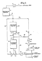
- Figure 1 is a schematic flow sheet showing the conversion reactor divided into two reactors of equal volume; and
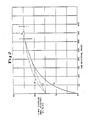
- Figure 2 is a graph showing the improvement in gasoline yield for divided reactor operation over undivided reactor operation.
- Referring to Figure 1 of the drawings, methanol passes through line 11 and
heat exchanger 12 and entersdehydration reactor 10 operating at an inlet temperature of 280 to 350°C and a pressure of 1480 to 2800 kPa and is converted into an equilibrium mixture of methanol, dimethyl ether, and water. An effluent mixture exits throughline 13 and mixes with light hydrocarbon recycle gas fromline 32. - Operation of
conversion reactors reactors 20 and 3Q is described for the preferred case in whichreactors downstream reactor 30 or by-passing ofdownstream reactor 30 with respect to effluent inline 13 fromdehydration reactor 10 during the early stage of a process cycle. This early stage ends when methanol appears in the effluent fromconversion reactor 20, termed "methanol break-through'. - At the beginning of the cycle,
valves valves conversion reactor 30 from effluent. The combined stream fromlines conversion reactor 20 atline 13 whereupon the combined stream is completely converted into a gasoline boiling-range hydrocarbon effluent emerging fromreactor 20 atline 21. Since valve 22 is initially closed, the effluent fromline 21 is diverted toline 23 and through open valve 24. The effluent stream passes throughline 23 toline 34 enteringheat exchanger 37 where it is cooled. The cooled effluent then enters highpressure separation unit 40 which separates the effluent into liquid water exiting atline 41, gasoline boiling-range hydrocarbons exiting atline 42 and light hydrocarbon gas exiting atline 43. The light hydrocarbon gas can be partially tapped off at line 44 in the form of a hydrocarbon gas product. The remaining light hydrocarbon gas followsline 43 throughcompressor 45 andheat exchanger 46, and then entersconversion reactor 30 vialines conversion reactor 30 at approximately 315 to 400°C. The gas then flows fromconversion reactor 30 throughlines line 13 where it is combined with the effluent frommethanol dehydration reactor 10. Operation in this mode continues until methanol break-through. - When the
conversion reactor 20 can no longer accomplish 100% conversion of methanol,valves valves line 13 and recycled gas fromline 49 to pass throughconversion reactor 20, where it is only partially converted due to the deactivated state of the catalyst, . toline 21. The partially converted hydrocarbon effluent passes through open valve 22 and entersconversion reactor 30 to achieve complete conversion of methanol. The converted methanol exitsconversion reactor 30 atline 31. The effluent passes throughheat exchanger 37 vialine 34 and entersseparation unit 40 wherein it is again separated into liquid water, gasoline boiling-range hydrocarbons, and light hydrocarbon gas. The light hydrocarbon gas exitsseparation unit 40 atline 43 and passes throughcompressor 45 andheat exchanger 46 toline 49 and combines with the effluent frommethanol dehydration reactor 10 atline 13. - The cycle continues until methanol is detected in
line 31. At this point, if onlyconversion reactors reactors reactors - Figure 2 illustrates some of the advantages of the modified cyclic process over the unmodified process. The product stream tested is 9 RVP gasoline. Curve A indicates gasoline yield (weight percent) as a function of time for the unmodified process during the first cycle. Curve B estimates gasoline yield for the modified cyclic process according to the invention in which the conversion reactor has been divided into two equal-volume reactors connected in series. The total quantity of conversion catalyst in each reactor system is identical. Curve C is a conservative estimate of gasoline yield for the modified process. Figure 2 shows that the estimated average gasoline yield for the modified cyclic system is between 81 and 82 weight percent compared to 78% for the unmodified system. In addition, the cycle length of the modified system is extended at D. The increased cycle length is due in part to the extended ultimate catalyst life in the modified system. By splitting the conversion reactor into smaller units operating cyclically, the steam which results from methanol conversion and water naturally occurring in the feed methanol has no opportunity to prematurely deactivate the catalyst in the isolated reactor beds of the second stage. This is because these beds have only light hydrocarbon recycle gas flowing through them. This recycle gas contains only a very small quantity of water vapor which is determined by the conditions of the high pressure separator.
Claims (7)
Applications Claiming Priority (2)
| Application Number | Priority Date | Filing Date | Title |
|---|---|---|---|
| US352417 | 1982-02-25 | ||
| US06/352,417 US4523046A (en) | 1982-02-25 | 1982-02-25 | Method for gasoline yield enhancement in the fixed bed methanol-to-gasoline process |
Publications (2)
| Publication Number | Publication Date |
|---|---|
| EP0087862A1 EP0087862A1 (en) | 1983-09-07 |
| EP0087862B1 true EP0087862B1 (en) | 1986-03-26 |
Family
ID=23385047
Family Applications (1)
| Application Number | Title | Priority Date | Filing Date |
|---|---|---|---|
| EP83300614A Expired EP0087862B1 (en) | 1982-02-25 | 1983-02-08 | Process for converting methanol into gasoline with enhanced gasoline yield |
Country Status (8)
| Country | Link |
|---|---|
| US (1) | US4523046A (en) |
| EP (1) | EP0087862B1 (en) |
| JP (1) | JPS58157893A (en) |
| AR (1) | AR246073A1 (en) |
| AU (1) | AU552750B2 (en) |
| DE (1) | DE3362647D1 (en) |
| NZ (1) | NZ203105A (en) |
| ZA (1) | ZA83674B (en) |
Families Citing this family (23)
| Publication number | Priority date | Publication date | Assignee | Title |
|---|---|---|---|---|
| US4482772A (en) * | 1983-11-03 | 1984-11-13 | Mobil Oil Corporation | Multistage process for converting oxygenates to hydrocarbons |
| US4579999A (en) * | 1985-01-17 | 1986-04-01 | Mobil Oil Corporation | Multistage process for converting oxygenates to liquid hydrocarbons with aliphatic recycle |
| US4654453A (en) * | 1985-09-23 | 1987-03-31 | Mobil Oil Corporation | Process for converting oxygenates to hydrocarbons |
| US4985203A (en) * | 1985-09-23 | 1991-01-15 | Mobil Oil Corporation | Conversion system for converting oxygenates to hydrocarbons |
| US4788369A (en) * | 1985-12-31 | 1988-11-29 | Mobil Oil Corporation | Conversion of methanol to gasoline |
| US4746761A (en) * | 1986-07-18 | 1988-05-24 | Mobil Oil Corporation | Process for coverting methanol to alkyl ethers |
| US4684757A (en) * | 1986-07-18 | 1987-08-04 | Mobil Oil Corporation | Process for converting methanol to alkyl ethers, gasoline, distillate and alkylate liquid hydrocarbons |
| US4919790A (en) * | 1988-01-19 | 1990-04-24 | Mobil Oil Corporation | Method for hydrocarbon dewaxing utilizing a reactivated spent MTG zeolite catalyst |
| JP5023638B2 (en) * | 2006-09-27 | 2012-09-12 | 三菱化学株式会社 | Propylene production method |
| DE102009046790B9 (en) | 2009-11-17 | 2013-05-08 | Chemieanlagenbau Chemnitz Gmbh | Process for the production of hydrocarbons, in particular gasoline, from synthesis gas |
| JP5863421B2 (en) | 2011-11-30 | 2016-02-16 | 三菱重工業株式会社 | System or method for producing gasoline or dimethyl ether |
| JP6116801B2 (en) | 2012-01-17 | 2017-04-19 | 三菱重工業株式会社 | System or method for producing gasoline |
| JP5995447B2 (en) | 2012-01-17 | 2016-09-21 | 三菱重工業株式会社 | Gasoline production equipment |
| EA035172B1 (en) * | 2015-01-22 | 2020-05-12 | Хальдор Топсёэ А/С | Hydrogen rejection in methanol to hydrocarbon process |
| CN106146236B (en) * | 2015-05-15 | 2019-06-18 | 内蒙古丰汇化工有限公司 | The method that hydrocarbon products is prepared by methanol two-step method |
| WO2017173165A1 (en) * | 2016-03-31 | 2017-10-05 | Vertimass, LLC | Systems and methods for improving yields of hydrocarbon fuels from alcohols |
| US9981896B2 (en) | 2016-07-01 | 2018-05-29 | Res Usa, Llc | Conversion of methane to dimethyl ether |
| US9938217B2 (en) | 2016-07-01 | 2018-04-10 | Res Usa, Llc | Fluidized bed membrane reactor |
| US10189763B2 (en) | 2016-07-01 | 2019-01-29 | Res Usa, Llc | Reduction of greenhouse gas emission |
| EP3670443A1 (en) | 2018-12-20 | 2020-06-24 | Forschungszentrum Jülich GmbH | Method and device for producing liquid fluid |
| DE102019200245A1 (en) | 2019-01-10 | 2020-07-16 | Forschungszentrum Jülich GmbH | Method and device for producing liquid fuel |
| CN116194557A (en) * | 2020-09-25 | 2023-05-30 | 托普索公司 | Alternative Methanol To Olefins (MTO) process |
| KR20220148517A (en) | 2021-04-29 | 2022-11-07 | 현대자동차주식회사 | Catalyst for gasoline synthesis from dimethyl ether, method for preparing the same, and method for preparing gasoline using the same |
Family Cites Families (17)
| Publication number | Priority date | Publication date | Assignee | Title |
|---|---|---|---|---|
| US2299197A (en) * | 1939-09-07 | 1942-10-20 | Standard Oil Co | Catalytic unit |
| US4052479A (en) * | 1973-08-09 | 1977-10-04 | Mobil Oil Corporation | Conversion of methanol to olefinic components |
| JPS50129475A (en) * | 1974-04-01 | 1975-10-13 | ||
| JPS50135733U (en) * | 1974-04-25 | 1975-11-08 | ||
| US4058576A (en) * | 1974-08-09 | 1977-11-15 | Mobil Oil Corporation | Conversion of methanol to gasoline components |
| US3931349A (en) * | 1974-09-23 | 1976-01-06 | Mobil Oil Corporation | Conversion of methanol to gasoline components |
| US4138442A (en) * | 1974-12-05 | 1979-02-06 | Mobil Oil Corporation | Process for the manufacture of gasoline |
| US3998899A (en) * | 1975-08-06 | 1976-12-21 | Mobil Oil Corporation | Method for producing gasoline from methanol |
| JPS5221277A (en) * | 1975-08-12 | 1977-02-17 | Seitetsu Kagaku Co Ltd | Method of catalytic reaction and its apparatus |
| US4035430A (en) * | 1976-07-26 | 1977-07-12 | Mobil Oil Corporation | Conversion of methanol to gasoline product |
| US4150062A (en) * | 1976-12-20 | 1979-04-17 | Mobil Oil Corporation | Light olefin processing |
| JPS6044009B2 (en) * | 1977-02-08 | 1985-10-01 | 日本碍子株式会社 | Method for removing nitrogen oxides from exhaust gas |
| US4231899A (en) * | 1979-01-22 | 1980-11-04 | Mobil Oil Corporation | Method of producing a steam stable aluminosilicate zeolite catalyst |
| US4423266A (en) * | 1980-10-08 | 1983-12-27 | Mobil Oil Corporation | Extending isomerization catalyst life by treating with phosphorous and/or steam |
| US4260841A (en) * | 1979-09-04 | 1981-04-07 | Mobil Oil Corporation | Conversion of oxygenated products of Fischer-Tropsch synthesis |
| US4418235A (en) * | 1980-02-14 | 1983-11-29 | Mobil Oil Corporation | Hydrocarbon conversion with zeolite having enhanced catalytic activity |
| US4326994A (en) * | 1980-02-14 | 1982-04-27 | Mobil Oil Corporation | Enhancement of zeolite catalytic activity |
-
1982
- 1982-02-25 US US06/352,417 patent/US4523046A/en not_active Expired - Fee Related
-
1983
- 1983-01-27 NZ NZ203105A patent/NZ203105A/en unknown
- 1983-02-01 ZA ZA83674A patent/ZA83674B/en unknown
- 1983-02-04 AU AU11146/83A patent/AU552750B2/en not_active Ceased
- 1983-02-08 DE DE8383300614T patent/DE3362647D1/en not_active Expired
- 1983-02-08 EP EP83300614A patent/EP0087862B1/en not_active Expired
- 1983-02-24 AR AR83292227A patent/AR246073A1/en active
- 1983-02-25 JP JP58029576A patent/JPS58157893A/en active Granted
Also Published As
| Publication number | Publication date |
|---|---|
| EP0087862A1 (en) | 1983-09-07 |
| ZA83674B (en) | 1984-09-26 |
| JPS58157893A (en) | 1983-09-20 |
| US4523046A (en) | 1985-06-11 |
| DE3362647D1 (en) | 1986-04-30 |
| AU1114683A (en) | 1983-09-01 |
| NZ203105A (en) | 1985-01-31 |
| AR246073A1 (en) | 1994-03-30 |
| AU552750B2 (en) | 1986-06-19 |
| JPH0451596B2 (en) | 1992-08-19 |
Similar Documents
| Publication | Publication Date | Title |
|---|---|---|
| EP0087862B1 (en) | Process for converting methanol into gasoline with enhanced gasoline yield | |
| US3931349A (en) | Conversion of methanol to gasoline components | |
| US4058576A (en) | Conversion of methanol to gasoline components | |
| US4404414A (en) | Conversion of methanol to gasoline | |
| US4749820A (en) | Integration of paraffin dehydrogenation with MOGD to minimize compression and gas plant separation | |
| US8052938B2 (en) | Aromatics co-production in a methanol-to-propylene unit | |
| CN101351423B (en) | Light olefin production via dimethyl ether | |
| US4542247A (en) | Conversion of LPG hydrocarbons to distillate fuels or lubes using integration of LPG dehydrogenation and MOGDL | |
| RU2550354C1 (en) | Method for producing aromatic hydrocarbon concentrate of light aliphatic hydrocarbons and device for implementing it | |
| JP2008513448A (en) | Conversion of alcoholic oxygenates to propylene using moving bed technology and etherification process. | |
| WO2006020083A1 (en) | Processes for converting oxygenates to olefins at reduced volumetric flow rates | |
| US4678645A (en) | Conversion of LPG hydrocarbons to distillate fuels or lubes using integration of LPG dehydrogenation and MOGDL | |
| US8735639B2 (en) | Preparing a light-olefin containing product stream from an oxygenate-containing feed steam using reactors directing a flow of a fluidized dual-function catalyst system | |
| JPH0378376B2 (en) | ||
| WO2012039999A2 (en) | Integration of cyclic dehydrogenation process with fcc for dehydrogenation of refinery paraffins | |
| RU2417249C1 (en) | Procedure for production of high-octane benzine or aromatic hydrocarbons | |
| EP0088494B1 (en) | Process for converting methanol into olefins | |
| US20080081936A1 (en) | Integrated processing of methanol to olefins | |
| US5712313A (en) | Process for carrying out chemical equilibrium reactions | |
| CN111056901B (en) | Reaction system and reaction method for preparing aromatic hydrocarbon through catalytic conversion of methanol | |
| CN110536878B (en) | Method and system for converting acyclic hydrocarbons | |
| EP3080059B1 (en) | Alkanol to alkylene conversion using at least two different catalysts in sequential order | |
| KR100415499B1 (en) | How to prepare ethylbenzene | |
| GB2104094A (en) | Dehydrogenation process | |
| CN117326910A (en) | Method for increasing propylene yield by olefin pyrolysis, propylene yield increasing system and application |
Legal Events
| Date | Code | Title | Description |
|---|---|---|---|
| PUAI | Public reference made under article 153(3) epc to a published international application that has entered the european phase |
Free format text: ORIGINAL CODE: 0009012 |
|
| AK | Designated contracting states |
Designated state(s): BE DE FR GB IT NL |
|
| 17P | Request for examination filed |
Effective date: 19840207 |
|
| GRAA | (expected) grant |
Free format text: ORIGINAL CODE: 0009210 |
|
| AK | Designated contracting states |
Kind code of ref document: B1 Designated state(s): BE DE FR GB IT NL |
|
| REF | Corresponds to: |
Ref document number: 3362647 Country of ref document: DE Date of ref document: 19860430 |
|
| ET | Fr: translation filed | ||
| ITF | It: translation for a ep patent filed |
Owner name: MODIANO & ASSOCIATI S.R.L. |
|
| PLBE | No opposition filed within time limit |
Free format text: ORIGINAL CODE: 0009261 |
|
| STAA | Information on the status of an ep patent application or granted ep patent |
Free format text: STATUS: NO OPPOSITION FILED WITHIN TIME LIMIT |
|
| 26N | No opposition filed | ||
| ITTA | It: last paid annual fee | ||
| PGFP | Annual fee paid to national office [announced via postgrant information from national office to epo] |
Ref country code: DE Payment date: 19911217 Year of fee payment: 10 |
|
| PGFP | Annual fee paid to national office [announced via postgrant information from national office to epo] |
Ref country code: GB Payment date: 19911218 Year of fee payment: 10 |
|
| PGFP | Annual fee paid to national office [announced via postgrant information from national office to epo] |
Ref country code: FR Payment date: 19920107 Year of fee payment: 10 |
|
| PGFP | Annual fee paid to national office [announced via postgrant information from national office to epo] |
Ref country code: BE Payment date: 19920127 Year of fee payment: 10 |
|
| PGFP | Annual fee paid to national office [announced via postgrant information from national office to epo] |
Ref country code: NL Payment date: 19920229 Year of fee payment: 10 |
|
| PG25 | Lapsed in a contracting state [announced via postgrant information from national office to epo] |
Ref country code: GB Effective date: 19930208 |
|
| PG25 | Lapsed in a contracting state [announced via postgrant information from national office to epo] |
Ref country code: BE Effective date: 19930228 |
|
| BERE | Be: lapsed |
Owner name: MOBIL OIL CORP. Effective date: 19930228 |
|
| PG25 | Lapsed in a contracting state [announced via postgrant information from national office to epo] |
Ref country code: NL Effective date: 19930901 |
|
| GBPC | Gb: european patent ceased through non-payment of renewal fee |
Effective date: 19930208 |
|
| NLV4 | Nl: lapsed or anulled due to non-payment of the annual fee | ||
| PG25 | Lapsed in a contracting state [announced via postgrant information from national office to epo] |
Ref country code: FR Effective date: 19931029 |
|
| PG25 | Lapsed in a contracting state [announced via postgrant information from national office to epo] |
Ref country code: DE Effective date: 19931103 |
|
| REG | Reference to a national code |
Ref country code: FR Ref legal event code: ST |