EP0087743A2 - Orbital speed reducer with compensation coupling - Google Patents
Orbital speed reducer with compensation coupling Download PDFInfo
- Publication number
- EP0087743A2 EP0087743A2 EP83101739A EP83101739A EP0087743A2 EP 0087743 A2 EP0087743 A2 EP 0087743A2 EP 83101739 A EP83101739 A EP 83101739A EP 83101739 A EP83101739 A EP 83101739A EP 0087743 A2 EP0087743 A2 EP 0087743A2
- Authority
- EP
- European Patent Office
- Prior art keywords
- rotor
- drive
- speed reducer
- shaft
- drive shaft
- Prior art date
- Legal status (The legal status is an assumption and is not a legal conclusion. Google has not performed a legal analysis and makes no representation as to the accuracy of the status listed.)
- Granted
Links
- 239000003638 chemical reducing agent Substances 0.000 title claims abstract description 29
- 230000008878 coupling Effects 0.000 title claims description 15
- 238000010168 coupling process Methods 0.000 title claims description 15
- 238000005859 coupling reaction Methods 0.000 title claims description 15
- 230000009467 reduction Effects 0.000 abstract description 4
- 238000003754 machining Methods 0.000 abstract description 2
- 230000007246 mechanism Effects 0.000 description 10
- 238000000034 method Methods 0.000 description 4
- 230000000694 effects Effects 0.000 description 3
- 230000008859 change Effects 0.000 description 2
- 238000010276 construction Methods 0.000 description 2
- 230000008439 repair process Effects 0.000 description 2
- 101100400378 Mus musculus Marveld2 gene Proteins 0.000 description 1
- 238000010521 absorption reaction Methods 0.000 description 1
- 230000008901 benefit Effects 0.000 description 1
- 239000013013 elastic material Substances 0.000 description 1
- 230000007613 environmental effect Effects 0.000 description 1
- 230000003993 interaction Effects 0.000 description 1
- 230000010355 oscillation Effects 0.000 description 1
- 235000012771 pancakes Nutrition 0.000 description 1
- 230000010363 phase shift Effects 0.000 description 1
- 230000000717 retained effect Effects 0.000 description 1
- 230000001052 transient effect Effects 0.000 description 1
Images


Classifications
-
- F—MECHANICAL ENGINEERING; LIGHTING; HEATING; WEAPONS; BLASTING
- F16—ENGINEERING ELEMENTS AND UNITS; GENERAL MEASURES FOR PRODUCING AND MAINTAINING EFFECTIVE FUNCTIONING OF MACHINES OR INSTALLATIONS; THERMAL INSULATION IN GENERAL
- F16H—GEARING
- F16H1/00—Toothed gearings for conveying rotary motion
- F16H1/28—Toothed gearings for conveying rotary motion with gears having orbital motion
- F16H1/32—Toothed gearings for conveying rotary motion with gears having orbital motion in which the central axis of the gearing lies inside the periphery of an orbital gear
-
- F—MECHANICAL ENGINEERING; LIGHTING; HEATING; WEAPONS; BLASTING
- F16—ENGINEERING ELEMENTS AND UNITS; GENERAL MEASURES FOR PRODUCING AND MAINTAINING EFFECTIVE FUNCTIONING OF MACHINES OR INSTALLATIONS; THERMAL INSULATION IN GENERAL
- F16H—GEARING
- F16H1/00—Toothed gearings for conveying rotary motion
- F16H1/28—Toothed gearings for conveying rotary motion with gears having orbital motion
- F16H1/48—Special means compensating for misalignment of axes, e.g. for equalising distribution of load on the face width of the teeth
Definitions
- This invention relates to an orbital speed reducer having an improved drive system. More particularly it relates to a drive system for eliminating radial forces on the drive mechanism and thereby increasing the life of the bearing structure and facilitating the repair or interchange of drive motors.
- the invention is embodied in a speed reducer, suitable for precision motion control applications, of the type decribed above in which a compensation coupling is interposed between the drive shaft and an orbitally driven rotor.
- the compensation coupling is arranged to provide rotary motion of a rotor drive element or wheel carried by the rotor while permitting deviation of the rotor from its prescribed orbital path without creating radial forces on the drive shaft.
- an orbitally-driven rotor mounted for free rotation on a rotor drive element driven in a rotary path by a drive shaft, has a perimeter defined by an epitrochoidal curve that simultaneously engages each of a series of surrounding rollers mounted on a stationary support, the number of lobes on the rotor being equal to one less than the number of surrounding rollers.
- Rotation of the drive shaft causes the rotor to move orbitally and to rotate with a speed reduction equal to the reciprocal of the number of lobes on the rotor.
- a similar structure may serve as a second stage with a second orbital rotor driven by the first rotor and moved orbitally by the same eccentric. The second stage provides a further speed reduction to an output drive, provided by a rotatable output disk supporting the rollers in the second stage.
- the rotor drive element is driven in a rotary path by a variable-length crank arm that provides only rotary thrust and does not transmit radial forces to the drive shaft.
- This compensation coupling may take the form of a driving sleeve keyed or otherwise secured to a drive shaft that extends into and makes a sliding fit within a slot in a circular rotor drive element mounted for free rotation within a rotor that follows an orbital path.
- the driving sleeve slidably engages two opposing internal faces of the slot in the rotor drive element at points displaced radially outwardly from the axis of the drive shaft.
- the driving sleeve thus forms a crank mechansim, the slot in the rotor drive element being long enough to permit the desired radial movement of the rotor drive element and rotor assembly.
- Radial movement generated by the interaction of the rotor and the surrounding rollers and transmitted along a first line parallel with the longitudinal axis of the slot result only in movement of the rotor drive element along the axis of its slot and have no effect other than a slight change in the effective length of the crank arm.
- Radial movement forces transmitted along a line perpendicular to the longitudinal axis of the slot merely aid or oppose the torque of the drive motor and result in nothing more than a slight phase shift. Movement at intermediate angles produce a combination of these two effects.
- the drive shaft is thus protected from high radial forces irrespective of the direction of the movements that would otherwise give rise to those forces.
- the driving surfaces of the sleeve extension at the points of contact with the opposing surfaces of the rotor drive wheel form an arc of a circle so that radial movement perpendicular to the axis of the slot will not cause locking or binding upon slight rotary movement of the rotor drive element caused by these radial movements and so that the driving surfaces will at all times remain in firm engagement with the faces of the slot and not become a source of backlash.
- a longitudinal slot in the end of the driving sleeve divides it into two fingers, each providing one of the driving surfaces that press against the faces of the slot in the rotor drive element eccentric with a compliant force equal to or greater than the maximum torque to be developed under full load conditions. For larger units, an adjustment screw permits precise adjustment of the distance between the drive surfaces of the fingers.
- a compensation coupling As shown in the drawings, a compensation coupling, generally indicated at 2, includes a driving sleeve 3 secured to a drive shaft 4 by a set screw 6 that engages a flat section 8 on the shaft 4. One end portion of the driving sleeve 3 is cut away to form an extension 12 that extends into a slot 14 in a rotor drive element 16 rotatably mounted in an anti-friction bearing 18 that is, in turn, rotatably retained in an opening in an orbital rotor 22.
- rollers 24, each supported by a shaft 26, are mounted on a supporting disk 28 and arranged equally spaced in a circle to form an operating structure somewhat similar to an internal ring gear.
- the perimeter of the rotor 22 is formed by a series of thirteen external lobes 22a defined by an epitrochoidal curve and is at all times in engagement with the rollers 24.
- the sleeve extension 12 drives the rotor drive element 16 about a rotary path that is offset from the axis of the shaft 4 causing the rotor 22 to move orbitally, during which movement the outer surface of the rotor remains at all times in contact with each of the rollers 24.
- This orbital movement of the rotor causes it to revolve about its own axis at a speed equal to one-thirteenth the speed of the shaft 4 and in the opposite direction.
- the driving sleeve 3 of the compensation coupling 2 is shown in more detail in Figures 2-4.
- a cyclindrical portion 34 of the sleeve 2 has a threaded opening 36 that receives the screw 6.
- the extension 12, formed integrally with the cyclindrical portion 34, extends approximately one third of the distance around the full circle of the cylindrical portion 34.
- Two opposed drive surfaces 38 and 42 of the extension 12 form, in the plane perpendicular to the longitudinal axis of the shaft 4, arcs of a circle having a diameter equal to the width of the slot 14 ( Figure 1).
- the arcuate drive surfaces 38 and 42 remain in firm engagement with the adjacent internal faces of the slot. With an arc of greater radius, there would be an increasing likelihood of binding, and with an arc of lesser radius there would be a loss of contact giving rise to backlash or lost motion.
- the surfaces 38 and 42 are crowned also along a direction parallel with the longitudinal axis of the sleeve 3 as shown in Figure 2.
- the surfaces 38 and 42 of the driving sleeve 3 engage opposing rectilinear internal faces of the slot 14. To further prevent this coupling from introducing backlash or lost motion into the speed reducer and avoid any possibility of binding, the surfaces 38 and 42 are maintained at all times in close engagement with the internal faces of the slot 14.
- the surfaces 38 and 42 are dimensioned to maintain constant pressure against the internal faces of the slot 14 and the stiffness of the fingers 12a and 12b of the sleeve 3 are such that at full driving torque there is no significant deflection of the fingers 12a and 12b.
- the ends 46 and 48 ( Figure 1) of the slot 14 are curved and the length of the slot is great enough to allow for the radial movement of the rotor drive wheel.
- Figure 6 shows the same sleeve extension 12 in which an adjustment screw 50 is in threaded engagement with the finger 42 and extends across the slot 44 to abut the adjacent surface of the finger 38.
- a radial movement of rotor 22 and the rotor drive element 16, along a line y-y in Figure 1 causes the rotor drive element to move parallel with the line y-y relative to the driving sleeve 2 so that no radial force from this source is applied to the drive shaft 4 while the compensation coupling 2 continues to apply rotary force to the rotor drive wheel 16.
- a radial movement along the line x-x creates a rotary movement against the torque of the motor, shifting the phase of the drive but the only radial force is caused by the driving torque generated by the shaft 4 and is equal to the torque divided by the length of the crank arm.
- the shaft 4 is driven, in this example, by a pancake motor 52 ( Figure 5) suitably secured to one end of the speed reducer as by screws 54.
- the drive shaft is supported by two bearings in the speed reducing unit, but in this example the motor drive shaft is secured to the sleeve 2 which provides the only bearing support for the shaft 4 within the speed reducing unit. This construction is possible because of the limitation of radial forces on the drive shaft 4.
- the disk 28 is integral with the housing of the speed reducer.
- the rotor 22 is a two-stage rotor, the second stage of which drives an output disk 56.
- the disk 56 is mounted for rotation relative to the disk 28 by a bearing surface 58. All of the elements of this speed reducer save the compensation coupling are described more fully in my U. S. Patent 3,998,112 and the above-referenced copending applications.
- the arrangement shown here facilitates replacement of the motor 52 since access to only one end of the speed reducing mechanism is required.
- Motor removal is accomplished merely by removing the motor mount screws 54.
- This method of motor removal is particularly advantageous when the speed reducer is used as a motion control device such as the motive force and positioning device for a robot arm.
- the robot arm, or some other heavy or complex mechanism is secured to the end of the speed reducer opposite the motor and would have to be removed to replace or repair the motor in speed reducers of the types heretofore in use.
Abstract
Description
- This application is a continuation in part of my copending U.S. Patent Application entitled SPEED REDUCER AND METHOD FOR REDUCING BACKLASH, Serial No. , filed February 1, 1982 and of my copending U.S. Patent Application entitled SPEED REDUCER WITH ANTI-BACKLASH BEARING, Serial No. , filed of even date herewith.
- This invention relates to an orbital speed reducer having an improved drive system. More particularly it relates to a drive system for eliminating radial forces on the drive mechanism and thereby increasing the life of the bearing structure and facilitating the repair or interchange of drive motors.
- Speed reduction mechanisms making use of epicyclical movements with gear-like rotors having a perimeter defined by an epitrochoid curve have long been known. The magazine Design News in its August 18, 1961 issue describes a single-stage cycloidal cam that forms the basis of a speed reducing mechanism. A similar structure is shown in my U.S. Patent 3,998,112. Corresponding devices were previously known that made use of spur gears. U.S. Patent 2,250,259 to Foote, Jr. describes such a heliocen- tric unit. Other related mechanisms are described in U.S. Patents 3,429,393; 3,144,791; and 3,783,712.
- In operation, most of these speed reducing mechan- sims generate radial forces on the drive shaft or its bearings that increases wear, requires stronger drive shafts and associated mechanisms, and makes necessary at least two spaced bearing supports for the drive shaft. To eliminate or limit these radial forces, some of the prior art devices are constructed with substantial tolerances between the cycloidal cam and the associated rollers or, in a gear type unit, between the teeth of the sun and planet gears. Such tolerances inevitably result in backlash that renders the unit unsatisfactory for precision motion control applications.
- The invention is embodied in a speed reducer, suitable for precision motion control applications, of the type decribed above in which a compensation coupling is interposed between the drive shaft and an orbitally driven rotor. The compensation coupling is arranged to provide rotary motion of a rotor drive element or wheel carried by the rotor while permitting deviation of the rotor from its prescribed orbital path without creating radial forces on the drive shaft.
- In the unit described here, an orbitally-driven rotor, mounted for free rotation on a rotor drive element driven in a rotary path by a drive shaft, has a perimeter defined by an epitrochoidal curve that simultaneously engages each of a series of surrounding rollers mounted on a stationary support, the number of lobes on the rotor being equal to one less than the number of surrounding rollers. Rotation of the drive shaft causes the rotor to move orbitally and to rotate with a speed reduction equal to the reciprocal of the number of lobes on the rotor. A similar structure may serve as a second stage with a second orbital rotor driven by the first rotor and moved orbitally by the same eccentric. The second stage provides a further speed reduction to an output drive, provided by a rotatable output disk supporting the rollers in the second stage.
- In accordance with the present invention, the rotor drive element is driven in a rotary path by a variable-length crank arm that provides only rotary thrust and does not transmit radial forces to the drive shaft. This compensation coupling may take the form of a driving sleeve keyed or otherwise secured to a drive shaft that extends into and makes a sliding fit within a slot in a circular rotor drive element mounted for free rotation within a rotor that follows an orbital path. The driving sleeve slidably engages two opposing internal faces of the slot in the rotor drive element at points displaced radially outwardly from the axis of the drive shaft. The driving sleeve thus forms a crank mechansim, the slot in the rotor drive element being long enough to permit the desired radial movement of the rotor drive element and rotor assembly. Radial movement generated by the interaction of the rotor and the surrounding rollers and transmitted along a first line parallel with the longitudinal axis of the slot, result only in movement of the rotor drive element along the axis of its slot and have no effect other than a slight change in the effective length of the crank arm. Radial movement forces transmitted along a line perpendicular to the longitudinal axis of the slot, merely aid or oppose the torque of the drive motor and result in nothing more than a slight phase shift. Movement at intermediate angles produce a combination of these two effects. The drive shaft is thus protected from high radial forces irrespective of the direction of the movements that would otherwise give rise to those forces.
- The driving surfaces of the sleeve extension at the points of contact with the opposing surfaces of the rotor drive wheel form an arc of a circle so that radial movement perpendicular to the axis of the slot will not cause locking or binding upon slight rotary movement of the rotor drive element caused by these radial movements and so that the driving surfaces will at all times remain in firm engagement with the faces of the slot and not become a source of backlash. A longitudinal slot in the end of the driving sleeve divides it into two fingers, each providing one of the driving surfaces that press against the faces of the slot in the rotor drive element eccentric with a compliant force equal to or greater than the maximum torque to be developed under full load conditions. For larger units, an adjustment screw permits precise adjustment of the distance between the drive surfaces of the fingers.
-
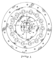
- Figure 1 is a diagrammatic illustration of the output end of a motion control unit embodying the invention to indicate the operationt;
- Figure 2 is a top view of the driving sleeve;
- Figure 3 is a sectional view along line 3-3 of Figure 2;
- Figure 4 is an end view along line 4-4 of Figure 2;
- Figure 5 is a sectional view through a speed reducer embodying the invention; and
- Figure 6 is a view similar to Figure 4 showing an adjustment screw for controlling the width of the sleeve extension.
- As shown in the drawings, a compensation coupling, generally indicated at 2, includes a
driving sleeve 3 secured to adrive shaft 4 by aset screw 6 that engages aflat section 8 on theshaft 4. One end portion of thedriving sleeve 3 is cut away to form anextension 12 that extends into aslot 14 in arotor drive element 16 rotatably mounted in an anti-friction bearing 18 that is, in turn, rotatably retained in an opening in anorbital rotor 22. - Fourteen
rollers 24, each supported by ashaft 26, are mounted on a supportingdisk 28 and arranged equally spaced in a circle to form an operating structure somewhat similar to an internal ring gear. The perimeter of therotor 22 is formed by a series of thirteen external lobes 22a defined by an epitrochoidal curve and is at all times in engagement with therollers 24. - When the
input shaft 4 is driven, thesleeve extension 12 drives therotor drive element 16 about a rotary path that is offset from the axis of theshaft 4 causing therotor 22 to move orbitally, during which movement the outer surface of the rotor remains at all times in contact with each of therollers 24. This orbital movement of the rotor causes it to revolve about its own axis at a speed equal to one-thirteenth the speed of theshaft 4 and in the opposite direction. The operation of the orbital rotor and associated rollers is fully described in my U.S. Patent 3,998,112 considered in conjunction with my two copending applications referenced above. - Limitations in machining accuracy and the effects of environmental and operational factors, such as temperature changes and stress resulting from applied loads, prevent the construction by usual methods of a precision unit that will not produce radial forces on the driving mechanism. If adequate tolerances are not provided in the dimensions, enormous radial forces can be produced on the driving mechansim. The above copending application entitled SPEED REDUCER AND METHOD FOR REDUCING BACKLASH describes an arrangement in which the rollers engaging the cycloidal rotor are supported by a preloaded structure providing omnidirectional controlled compliance. This preloading in cooperation with the controlled omnidirectional compliance prevents binding of the mechanism while equalizing the load among all of the rollers. Because the forces at the nodes of the lobes can approach infinity, effective load sharing among the rollers is achieved. The support for the rollers must be sufficiently rigid that the roller is not substantially deflected because of the load applied to the unit yet sufficiently compliant to compensate for other factors and prevent backlash. This arrangement permits reversal of the direction of drive without significant backlash, an important advantage in motion control applications. In any event, with or without such compliance in the roller positions, radial movements can be generated that, if not absorbed, would give rise to substantial forces on the drive mechanism. The absorption of these movements by flexible elements such as springs or elastic material such as rubber is likely to give rise to instability or transient oscillations in the motion control system and are therefore to be avoided.
- The driving
sleeve 3 of thecompensation coupling 2 is shown in more detail in Figures 2-4. Acyclindrical portion 34 of thesleeve 2 has a threadedopening 36 that receives thescrew 6. Theextension 12, formed integrally with thecyclindrical portion 34, extends approximately one third of the distance around the full circle of thecylindrical portion 34. Twoopposed drive surfaces extension 12 form, in the plane perpendicular to the longitudinal axis of theshaft 4, arcs of a circle having a diameter equal to the width of the slot 14 (Figure 1). When radial movements are generated that cause angular movement of theslot 14 relative to thesleeve extension 12, thearcuate drive surfaces surfaces sleeve 3 as shown in Figure 2. - The
surfaces driving sleeve 3 engage opposing rectilinear internal faces of theslot 14. To further prevent this coupling from introducing backlash or lost motion into the speed reducer and avoid any possibility of binding, thesurfaces slot 14. A spring force made possible by anexpansion slot 44 in the end of theextension 12 that divides the extension into twofingers surfaces slot 14 and the stiffness of thefingers sleeve 3 are such that at full driving torque there is no significant deflection of thefingers slot 14 are curved and the length of the slot is great enough to allow for the radial movement of the rotor drive wheel. - For larger units, the power requirements may not permit use of the simple compliance arrangement just described and a fixed but adjustable width of the sleeve extension is desirable. Figure 6 shows the
same sleeve extension 12 in which anadjustment screw 50 is in threaded engagement with thefinger 42 and extends across theslot 44 to abut the adjacent surface of thefinger 38. - In operation, a radial movement of
rotor 22 and therotor drive element 16, along a line y-y in Figure 1, causes the rotor drive element to move parallel with the line y-y relative to the drivingsleeve 2 so that no radial force from this source is applied to thedrive shaft 4 while thecompensation coupling 2 continues to apply rotary force to therotor drive wheel 16. A radial movement along the line x-x creates a rotary movement against the torque of the motor, shifting the phase of the drive but the only radial force is caused by the driving torque generated by theshaft 4 and is equal to the torque divided by the length of the crank arm. - The
shaft 4 is driven, in this example, by a pancake motor 52 (Figure 5) suitably secured to one end of the speed reducer as by screws 54. In the prior art devices referred to above, the drive shaft is supported by two bearings in the speed reducing unit, but in this example the motor drive shaft is secured to thesleeve 2 which provides the only bearing support for theshaft 4 within the speed reducing unit. This construction is possible because of the limitation of radial forces on thedrive shaft 4. - In the example illustrated in Figure 5, the
disk 28 is integral with the housing of the speed reducer. Therotor 22 is a two-stage rotor, the second stage of which drives anoutput disk 56. Thedisk 56 is mounted for rotation relative to thedisk 28 by a bearingsurface 58. All of the elements of this speed reducer save the compensation coupling are described more fully in my U. S. Patent 3,998,112 and the above-referenced copending applications. - The arrangement shown here facilitates replacement of the
motor 52 since access to only one end of the speed reducing mechanism is required. Motor removal is accomplished merely by removing the motor mount screws 54. This method of motor removal is particularly advantageous when the speed reducer is used as a motion control device such as the motive force and positioning device for a robot arm. The robot arm, or some other heavy or complex mechanism, is secured to the end of the speed reducer opposite the motor and would have to be removed to replace or repair the motor in speed reducers of the types heretofore in use. - From the foregoing it will be seen that the speed reducer described herein is suitable for the usual speed change applications, but is also particularly suitable for applications in precision motion control systems where backlash is an overriding consideration. It will be obvious that the particular structure used here to illustrate the invention is subject to many variations, all within the scope of the present invention, by which to best adapt the invention for each particular use.
Claims (13)
said rotor drive element has a radial opening therein with opposing internal faces engaging respectively said first and second drive surfaces.
said drive surface is crowned in a direction parallel with the longitudinal axis of said shaft.
said drive surface forms in a plane transverse to the longitudinal asis of said shaft an arc of a circle having a diameter substantially equal to the width of said radial opening.
each of said drive surfaces is crowned in a direction parallel with the longitudinal axis of said shaft.
each of said drive surfaces forms in a plane transverse to the longitudinal axis of said shaft an arc of a circle having a diameter equal to the width of said radial opening.
each of said drive surfaces is crowned in a direction parallel with the longitudinal axis of said shaft.
each of said drive surfaces forms in a plane transverse to the longitudinal axis of said shaft an arc of a circle having a diameter substantially equal to the distance between said opposing faces of said radial . opening.
Priority Applications (1)
| Application Number | Priority Date | Filing Date | Title |
|---|---|---|---|
| AT83101739T ATE27049T1 (en) | 1982-02-25 | 1983-02-23 | ROTARY REDUCTION GEAR WITH COMPENSATING CLUTCH. |
Applications Claiming Priority (2)
| Application Number | Priority Date | Filing Date | Title |
|---|---|---|---|
| US352122 | 1982-02-25 | ||
| US06/352,122 US4549450A (en) | 1982-02-25 | 1982-02-25 | Orbital speed reducer with compensation coupling |
Publications (3)
| Publication Number | Publication Date |
|---|---|
| EP0087743A2 true EP0087743A2 (en) | 1983-09-07 |
| EP0087743A3 EP0087743A3 (en) | 1985-01-09 |
| EP0087743B1 EP0087743B1 (en) | 1987-05-06 |
Family
ID=23383881
Family Applications (1)
| Application Number | Title | Priority Date | Filing Date |
|---|---|---|---|
| EP83101739A Expired EP0087743B1 (en) | 1982-02-25 | 1983-02-23 | Orbital speed reducer with compensation coupling |
Country Status (6)
| Country | Link |
|---|---|
| US (1) | US4549450A (en) |
| EP (1) | EP0087743B1 (en) |
| JP (1) | JPS58156749A (en) |
| AT (1) | ATE27049T1 (en) |
| CA (1) | CA1194710A (en) |
| DE (1) | DE3371400D1 (en) |
Cited By (3)
| Publication number | Priority date | Publication date | Assignee | Title |
|---|---|---|---|---|
| EP0474897A1 (en) * | 1990-09-10 | 1992-03-18 | Sumitomo Heavy Industries Co., Ltd. | Planetary speed changing device |
| US8033943B2 (en) | 2005-08-18 | 2011-10-11 | Ntn Corporation | In-wheel motor driving unit |
| FR3050504A1 (en) * | 2016-04-25 | 2017-10-27 | Jtekt Europe Sas | CYCLOIDAL REDUCER WITH AUTOMATIC GAME RELEASE AND POWER ASSISTED STEERING SYSTEM PROVIDED WITH SUCH REDUCER |
Families Citing this family (6)
| Publication number | Priority date | Publication date | Assignee | Title |
|---|---|---|---|---|
| US4914330A (en) * | 1989-03-09 | 1990-04-03 | Michel Pierrat | Low speed brushless electric motor |
| US5211611A (en) * | 1989-08-01 | 1993-05-18 | American Power Equipment Company | Planocentric drive mechanism |
| US5388483A (en) * | 1992-06-03 | 1995-02-14 | Sumimoto Heavy Industries, Ltd. | Internally meshing planetary gear structure and flexible meshing type gear meshing structure |
| US6902507B2 (en) * | 2002-04-11 | 2005-06-07 | Richard N. Ballard | Roller cam assembly |
| BRPI0702377A2 (en) * | 2007-08-02 | 2009-03-17 | Cunha Gravio Valmor Da | chain speed reducer |
| CN110985611A (en) * | 2019-05-22 | 2020-04-10 | 苏州华震工业机器人减速器有限公司 | Hollow speed reducer for precision control |
Citations (3)
| Publication number | Priority date | Publication date | Assignee | Title |
|---|---|---|---|---|
| GB955097A (en) * | 1960-05-16 | 1964-04-15 | Braren Rudolf | Planetary gear |
| US3998112A (en) * | 1974-12-06 | 1976-12-21 | Compudrive Corporation | Mechanical drives |
| US4016780A (en) * | 1975-03-03 | 1977-04-12 | Trochoidal Gear Technology, Inc. | Hypotrochoidal cluster gear drives |
Family Cites Families (10)
| Publication number | Priority date | Publication date | Assignee | Title |
|---|---|---|---|---|
| US1942794A (en) * | 1931-02-05 | 1934-01-09 | Melvin B Benson Corp | Speed reducer |
| US2303365A (en) * | 1939-11-14 | 1942-12-01 | Karlsen Karl Henry | Clock mechanism |
| US2250259A (en) * | 1940-03-11 | 1941-07-22 | Jr Bradford Foote | Speed reducing gearing |
| US3144791A (en) * | 1958-06-06 | 1964-08-18 | Aubry H Temple | Speed reducer |
| US3045503A (en) * | 1959-05-28 | 1962-07-24 | Square D Co | Control mechanism |
| US3429393A (en) * | 1966-12-08 | 1969-02-25 | Lorence Mfg Corp | Drive mechanism |
| BE770716A (en) * | 1971-07-30 | 1971-12-01 | Soudure Autogene Elect | FRICTION FREE SPEED REDUCER WITH LARGE REDUCTION RATIO. |
| DE2757907A1 (en) * | 1977-12-24 | 1979-07-05 | Keiper Automobiltechnik Gmbh | ARTICULATED FITTING FOR SEATS WITH ADJUSTABLE BACKREST, IN PARTICULAR MOTOR VEHICLE SEATS |
| US4348918A (en) * | 1979-02-21 | 1982-09-14 | Teijin Seiki Company Limited | Speed change device |
| DE3013304C2 (en) * | 1980-04-05 | 1983-05-11 | Keiper Automobiltechnik Gmbh & Co Kg, 5630 Remscheid | Adjusting device for seats and windows, in particular for motor vehicles |
-
1982
- 1982-02-25 US US06/352,122 patent/US4549450A/en not_active Expired - Fee Related
-
1983
- 1983-02-22 CA CA000422089A patent/CA1194710A/en not_active Expired
- 1983-02-23 EP EP83101739A patent/EP0087743B1/en not_active Expired
- 1983-02-23 DE DE8383101739T patent/DE3371400D1/en not_active Expired
- 1983-02-23 AT AT83101739T patent/ATE27049T1/en not_active IP Right Cessation
- 1983-02-25 JP JP58031698A patent/JPS58156749A/en active Granted
Patent Citations (3)
| Publication number | Priority date | Publication date | Assignee | Title |
|---|---|---|---|---|
| GB955097A (en) * | 1960-05-16 | 1964-04-15 | Braren Rudolf | Planetary gear |
| US3998112A (en) * | 1974-12-06 | 1976-12-21 | Compudrive Corporation | Mechanical drives |
| US4016780A (en) * | 1975-03-03 | 1977-04-12 | Trochoidal Gear Technology, Inc. | Hypotrochoidal cluster gear drives |
Cited By (8)
| Publication number | Priority date | Publication date | Assignee | Title |
|---|---|---|---|---|
| EP0474897A1 (en) * | 1990-09-10 | 1992-03-18 | Sumitomo Heavy Industries Co., Ltd. | Planetary speed changing device |
| US5123884A (en) * | 1990-09-10 | 1992-06-23 | Sumitomo Heavy Industries, Ltd. | Planetary speed changing device |
| US8033943B2 (en) | 2005-08-18 | 2011-10-11 | Ntn Corporation | In-wheel motor driving unit |
| US8038562B2 (en) | 2005-08-18 | 2011-10-18 | Ntn Corporation | Power transmission device |
| FR3050504A1 (en) * | 2016-04-25 | 2017-10-27 | Jtekt Europe Sas | CYCLOIDAL REDUCER WITH AUTOMATIC GAME RELEASE AND POWER ASSISTED STEERING SYSTEM PROVIDED WITH SUCH REDUCER |
| WO2017187055A1 (en) * | 2016-04-25 | 2017-11-02 | Jtekt Europe | Cycloidal reducer with backlash self-adjustment and power steering system with such a reducer |
| CN109073047A (en) * | 2016-04-25 | 2018-12-21 | 捷太格特欧洲公司 | Cycloidal reducer with backlash automatic adjustment and the power steering system with this retarder |
| US10926792B2 (en) | 2016-04-25 | 2021-02-23 | Jtekt Europe | Cycloidal reducer with backlash self-adjustment and power steering system with such a reducer |
Also Published As
| Publication number | Publication date |
|---|---|
| DE3371400D1 (en) | 1987-06-11 |
| JPS58156749A (en) | 1983-09-17 |
| EP0087743B1 (en) | 1987-05-06 |
| ATE27049T1 (en) | 1987-05-15 |
| US4549450A (en) | 1985-10-29 |
| EP0087743A3 (en) | 1985-01-09 |
| JPH0338458B2 (en) | 1991-06-10 |
| CA1194710A (en) | 1985-10-08 |
Similar Documents
| Publication | Publication Date | Title |
|---|---|---|
| US4487091A (en) | Speed reducer and method for reducing blacklash | |
| EP0305535B1 (en) | Epicyclic reduction gear | |
| US4228698A (en) | Speed reducer | |
| US4713985A (en) | Transmission apparatus | |
| JP3712515B2 (en) | Planetary gear set | |
| KR950001718B1 (en) | Controlling transmission | |
| EP0575561A1 (en) | Speed converter. | |
| GB1560181A (en) | Powered wrist joint | |
| EP0087743B1 (en) | Orbital speed reducer with compensation coupling | |
| JP4759607B2 (en) | Rotary reducer | |
| JP2759032B2 (en) | Decelerator | |
| GB2074694A (en) | Toothed gearing | |
| CN112343972A (en) | Speed reducer with movable teeth and fixed teeth in composite transmission and without side gap | |
| CN112219045A (en) | Fixed ratio traction or friction drive | |
| CA1210612A (en) | Differential rotary-to-rotary cam system to achieve long dwell periods with continuous rotary input | |
| EP0087742A2 (en) | Speed reducer with anti-backlash bearing | |
| JPH06307504A (en) | Tooth thickness variable gear | |
| CN216111962U (en) | Gear transmission mechanism and rotary equipment | |
| JPS62101943A (en) | Reducer | |
| JPH04266646A (en) | Epicyclic gear device | |
| US4452093A (en) | Drive unit | |
| WO1993014332A1 (en) | Motion transmitting device | |
| JP3556735B2 (en) | Reducer for electric power steering system | |
| CN116816891A (en) | Composite planetary transmission speed reducer and driving unit | |
| CN117450248A (en) | Planet wheel speed reducing structure and robot |
Legal Events
| Date | Code | Title | Description |
|---|---|---|---|
| PUAI | Public reference made under article 153(3) epc to a published international application that has entered the european phase |
Free format text: ORIGINAL CODE: 0009012 |
|
| AK | Designated contracting states |
Designated state(s): AT BE CH DE FR GB IT LI LU NL SE |
|
| PUAL | Search report despatched |
Free format text: ORIGINAL CODE: 0009013 |
|
| AK | Designated contracting states |
Designated state(s): AT BE CH DE FR GB IT LI LU NL SE |
|
| 17P | Request for examination filed |
Effective date: 19850423 |
|
| GRAA | (expected) grant |
Free format text: ORIGINAL CODE: 0009210 |
|
| AK | Designated contracting states |
Kind code of ref document: B1 Designated state(s): AT BE CH DE FR GB IT LI LU NL SE |
|
| PG25 | Lapsed in a contracting state [announced via postgrant information from national office to epo] |
Ref country code: LI Effective date: 19870506 Ref country code: CH Effective date: 19870506 Ref country code: BE Effective date: 19870506 Ref country code: AT Effective date: 19870506 |
|
| REF | Corresponds to: |
Ref document number: 27049 Country of ref document: AT Date of ref document: 19870515 Kind code of ref document: T |
|
| ITF | It: translation for a ep patent filed |
Owner name: JACOBACCI & PERANI S.P.A. |
|
| PG25 | Lapsed in a contracting state [announced via postgrant information from national office to epo] |
Ref country code: SE Effective date: 19870531 |
|
| REF | Corresponds to: |
Ref document number: 3371400 Country of ref document: DE Date of ref document: 19870611 |
|
| ET | Fr: translation filed | ||
| REG | Reference to a national code |
Ref country code: CH Ref legal event code: PL |
|
| PG25 | Lapsed in a contracting state [announced via postgrant information from national office to epo] |
Ref country code: LU Free format text: LAPSE BECAUSE OF NON-PAYMENT OF DUE FEES Effective date: 19880229 |
|
| PLBE | No opposition filed within time limit |
Free format text: ORIGINAL CODE: 0009261 |
|
| STAA | Information on the status of an ep patent application or granted ep patent |
Free format text: STATUS: NO OPPOSITION FILED WITHIN TIME LIMIT |
|
| 26N | No opposition filed | ||
| PGFP | Annual fee paid to national office [announced via postgrant information from national office to epo] |
Ref country code: FR Payment date: 19890225 Year of fee payment: 7 |
|
| ITTA | It: last paid annual fee | ||
| PGFP | Annual fee paid to national office [announced via postgrant information from national office to epo] |
Ref country code: NL Payment date: 19890228 Year of fee payment: 7 Ref country code: GB Payment date: 19890228 Year of fee payment: 7 |
|
| PG25 | Lapsed in a contracting state [announced via postgrant information from national office to epo] |
Ref country code: GB Effective date: 19900223 |
|
| PGFP | Annual fee paid to national office [announced via postgrant information from national office to epo] |
Ref country code: DE Payment date: 19900430 Year of fee payment: 8 |
|
| PG25 | Lapsed in a contracting state [announced via postgrant information from national office to epo] |
Ref country code: NL Effective date: 19900901 |
|
| NLV4 | Nl: lapsed or anulled due to non-payment of the annual fee | ||
| GBPC | Gb: european patent ceased through non-payment of renewal fee | ||
| PG25 | Lapsed in a contracting state [announced via postgrant information from national office to epo] |
Ref country code: FR Effective date: 19901031 |
|
| REG | Reference to a national code |
Ref country code: FR Ref legal event code: ST |
|
| PG25 | Lapsed in a contracting state [announced via postgrant information from national office to epo] |
Ref country code: DE Effective date: 19911101 |