EP0086679B1 - Stabilisateur d'énergie électrique variable - Google Patents
Stabilisateur d'énergie électrique variable Download PDFInfo
- Publication number
- EP0086679B1 EP0086679B1 EP83400060A EP83400060A EP0086679B1 EP 0086679 B1 EP0086679 B1 EP 0086679B1 EP 83400060 A EP83400060 A EP 83400060A EP 83400060 A EP83400060 A EP 83400060A EP 0086679 B1 EP0086679 B1 EP 0086679B1
- Authority
- EP
- European Patent Office
- Prior art keywords
- load
- stabilizer
- input signal
- inductance
- stabilizer according
- Prior art date
- Legal status (The legal status is an assumption and is not a legal conclusion. Google has not performed a legal analysis and makes no representation as to the accuracy of the status listed.)
- Expired
Links
- 239000003381 stabilizer Substances 0.000 title claims description 30
- 230000001939 inductive effect Effects 0.000 claims description 14
- 230000010349 pulsation Effects 0.000 claims description 10
- 235000021183 entrée Nutrition 0.000 description 4
- 239000003990 capacitor Substances 0.000 description 3
- XEEYBQQBJWHFJM-UHFFFAOYSA-N Iron Chemical group [Fe] XEEYBQQBJWHFJM-UHFFFAOYSA-N 0.000 description 1
- 230000033228 biological regulation Effects 0.000 description 1
- 230000005540 biological transmission Effects 0.000 description 1
- 230000007423 decrease Effects 0.000 description 1
- 230000003247 decreasing effect Effects 0.000 description 1
- 238000004146 energy storage Methods 0.000 description 1
- 230000000087 stabilizing effect Effects 0.000 description 1
- 230000001131 transforming effect Effects 0.000 description 1
- 238000004804 winding Methods 0.000 description 1
Images

Classifications
-
- H—ELECTRICITY
- H02—GENERATION; CONVERSION OR DISTRIBUTION OF ELECTRIC POWER
- H02M—APPARATUS FOR CONVERSION BETWEEN AC AND AC, BETWEEN AC AND DC, OR BETWEEN DC AND DC, AND FOR USE WITH MAINS OR SIMILAR POWER SUPPLY SYSTEMS; CONVERSION OF DC OR AC INPUT POWER INTO SURGE OUTPUT POWER; CONTROL OR REGULATION THEREOF
- H02M1/00—Details of apparatus for conversion
- H02M1/14—Arrangements for reducing ripples from DC input or output
-
- Y—GENERAL TAGGING OF NEW TECHNOLOGICAL DEVELOPMENTS; GENERAL TAGGING OF CROSS-SECTIONAL TECHNOLOGIES SPANNING OVER SEVERAL SECTIONS OF THE IPC; TECHNICAL SUBJECTS COVERED BY FORMER USPC CROSS-REFERENCE ART COLLECTIONS [XRACs] AND DIGESTS
- Y10—TECHNICAL SUBJECTS COVERED BY FORMER USPC
- Y10S—TECHNICAL SUBJECTS COVERED BY FORMER USPC CROSS-REFERENCE ART COLLECTIONS [XRACs] AND DIGESTS
- Y10S320/00—Electricity: battery or capacitor charging or discharging
- Y10S320/14—Battery acts as buffer
Definitions
- the present invention relates to a stabilizer of variable electrical energy by restoring a direct current output at a predetermined load, when it receives an input signal having a voltage and a pulsation both varying in a constant ratio.
- the input signal received by the stabilizer comes from a variable energy source, such as a variable voltage generator of the variable speed alternator type or else a wind or solar generator.
- the input signal can also be transmitted by an energy storage device; in particular, reference is made below to a kinetic energy accumulator (ACE) which makes it possible to store kinetic energy in its rotor as long as the latter is driven by an alternating electric generator.
- ACE kinetic energy accumulator
- ACE kinetic energy accumulator
- Such kinetic energy accumulators are intended for supplying, for example, a telephone exchange or an electrical device to an isolated site, such as a radio relay.
- the kinetic energy accumulator thus replaces the conventional battery of electrochemical accumulators distributing a DC voltage of the order of 48 to 50 volts.
- a means for stabilizing the electrical energy delivered by the accumulator e.g., after having been launched at high speed by the associated alternating electric generator, the accumulator restores its kinetic energy in the charge by a voltage which decreases progressively in constant proportion with the decreasing speed of rotation of the rotor of the accumulator.
- the voltage of the input signal therefore varies in frequency and in amplitude so that the users of kinetic energy accumulators have been led to design stabilizers which transform variable energy in frequency and in amplitude into a continuous energy of constant amplitude with the best possible yield.
- a known stabilizer includes a rectifier to rectify the alternating voltage which is supplied by the kinetic energy accumulator, and a dc-dc switching converter to stabilize the rectified voltage.
- this solution has the disadvantage of using electronic circuits which include a large number of components, which reduces the reliability of the stabilizer and generates steep-front currents which are the source of electromagnetic disturbances liable to generate transmission. telephone signals.
- the object of the present invention is to provide a simple and therefore inexpensive variable electrical energy stabilizer which comprises only passive components for transforming a variable input voltage in frequency and in amplitude into a direct output current having a constant amplitude.
- variable electrical energy stabilizer is as defined in claim 1.
- variable voltage signal E ko applied to the input terminals B of the variable electrical energy stabilizer is a single-phase signal.
- the stabilizer includes at least one inductive circuit which is constituted by a simple inductance L.
- the load of use here represented by a resistor R, is in series with the inductance L between the two terminals B.
- the current can be considered as practically constant when the frequency increases in a current range between i max and ( i max -10% i max ) - i min
- the current will be considered unusable for load R.
- L must be chosen such that L ⁇ >> R, for the range of usable currents.
- the current can be considered as constant.
- the input signal received by the stabilizer is polyphase, and in particular three phase.
- Fig. 3 shows a variable electrical energy stabilizer before three inputs 0 1 , 0 2 and 0 3 receiving the three single-phase signals from a three-phase input signal supplied by the kinetic accumulator.
- the inductive circuit CI of the stabilizer comprises three elementary inductive circuits respectively for each of the single-phase signals.
- Each elementary inductive circuit is composed of an inductance L 1 , L 2 , L 3 and two diodes D 11 , D 12 ; D 21 , D 22 ; D 31 , D 32 .
- the six diodes form a Graetz bridge to ensure the switching of the three phases one after the other.
- each elementary inductive circuit one of the terminals of the inductance L t , L 2 . L 3 is connected to the respective input ⁇ 1 , 0 2 , 0 3 and the other terminal of the inductor is connected to the common terminal of the two respective diodes D 11 , D 12 ; D 21 , D22; D 31 , D 32 .
- These diodes are in series and polarized directly between the negative terminal (-) and the positive terminal (+) of the load R.
- the three inductors L 1 , L 2 and L 3 are identical and can be produced by three identical windings around '' a laminated iron core with an air gap.
- the PB filter can be composed of an n structure.
- the horizontal branch of the PB filter includes an inductor •
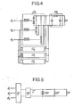
- FIG. 4 shows such a stabilizer which comprises four parallel inductive circuits Cl 1 to Cl 4 that are similar to CI inductive circuit of Fig. 3.
- the stabilizer according to the invention can be used as a constant voltage supply under constant current, in particular when the value of the impedance of the load R can vary.
- an accumulator battery BA is introduced in parallel at the terminals of the load R.
- the variations in the voltage at the terminals of the load which result from variations in the impedance of the load are absorbed by the battery BA; the additional current is used to charge the BA battery.
- the constant voltage can be additionally supplied by a Zener diode DZ which is in parallel with the load R.
Landscapes
- Engineering & Computer Science (AREA)
- Power Engineering (AREA)
- Ac-Ac Conversion (AREA)
- Control Of Electrical Variables (AREA)
- Rectifiers (AREA)
- Charge And Discharge Circuits For Batteries Or The Like (AREA)
Applications Claiming Priority (2)
| Application Number | Priority Date | Filing Date | Title |
|---|---|---|---|
| FR8202263 | 1982-02-11 | ||
| FR8202263A FR2521366A1 (fr) | 1982-02-11 | 1982-02-11 | Stabilisateur d'energie electrique variable |
Publications (2)
| Publication Number | Publication Date |
|---|---|
| EP0086679A1 EP0086679A1 (fr) | 1983-08-24 |
| EP0086679B1 true EP0086679B1 (fr) | 1986-09-03 |
Family
ID=9270896
Family Applications (1)
| Application Number | Title | Priority Date | Filing Date |
|---|---|---|---|
| EP83400060A Expired EP0086679B1 (fr) | 1982-02-11 | 1983-01-11 | Stabilisateur d'énergie électrique variable |
Country Status (4)
| Country | Link |
|---|---|
| US (1) | US4573004A (enExample) |
| EP (1) | EP0086679B1 (enExample) |
| DE (1) | DE3365743D1 (enExample) |
| FR (1) | FR2521366A1 (enExample) |
Families Citing this family (2)
| Publication number | Priority date | Publication date | Assignee | Title |
|---|---|---|---|---|
| SE9704480L (sv) * | 1997-08-25 | 1999-02-26 | Kwang Ju Electronics Co Ltd | Strömövertonsdämpningsanordning i en motor |
| BRPI0903548B1 (pt) * | 2009-06-05 | 2019-06-25 | Indústria De Motores Anauger S.a | Sistema de alimentação para uma carga indutiva a partir de uma fonte de energia com potência variável e sistema de alimentação para uma bomba vibratória a partir de células solares |
Family Cites Families (6)
| Publication number | Priority date | Publication date | Assignee | Title |
|---|---|---|---|---|
| US1571458A (en) * | 1915-12-31 | 1926-02-02 | Westinghouse Electric & Mfg Co | Electromagnetic production of direct current without fluctuations |
| US2214773A (en) * | 1938-01-22 | 1940-09-17 | Raytheon Mfg Co | Filter system for controlled rectifiers |
| US2930962A (en) * | 1957-08-30 | 1960-03-29 | Raytheon Co | Choke input power supplies |
| SU431590A1 (enExample) * | 1972-09-28 | 1974-06-05 | ||
| CH567344A5 (enExample) * | 1973-07-13 | 1975-09-30 | Zellweger Uster Ag | |
| DE2652275A1 (de) * | 1976-11-17 | 1978-05-18 | Boehringer Andreas | Einrichtung ohne prinzipbedingte verluste zur entnahme von praktisch rein sinusfoermigem, netzfrequentem strom aus wechsel- oder drehspannungsnetzen und zur ueberfuehrung der entnommenen elektrischen energie in galvanisch verbundene gleichspannungssysteme oder gleichspannungszwischensysteme |
-
1982
- 1982-02-11 FR FR8202263A patent/FR2521366A1/fr active Granted
-
1983
- 1983-01-11 EP EP83400060A patent/EP0086679B1/fr not_active Expired
- 1983-01-11 DE DE8383400060T patent/DE3365743D1/de not_active Expired
- 1983-01-19 US US06/459,266 patent/US4573004A/en not_active Expired - Fee Related
Also Published As
| Publication number | Publication date |
|---|---|
| FR2521366A1 (fr) | 1983-08-12 |
| DE3365743D1 (en) | 1986-10-09 |
| FR2521366B1 (enExample) | 1984-03-09 |
| EP0086679A1 (fr) | 1983-08-24 |
| US4573004A (en) | 1986-02-25 |
Similar Documents
| Publication | Publication Date | Title |
|---|---|---|
| EP0654887B1 (fr) | Alimentation sans coupure à neutre traversant, comportant un hacheur-élévateur double | |
| EP0347322B1 (fr) | Alimentation stabilisée à taux d'ondulation réduit | |
| EP2887527B1 (fr) | Bloc d'alimentation électrique compact et modulaire, multi-convertisseurs, notamment pour bornes de recharge rapide de véhicules électriques | |
| EP4320720A1 (fr) | Dispositif de création d'un bus de tension continue pour un système électrique polyphase, véhicule automobile et générateur à énergie renouvelable comprenant un tel dispositif | |
| EP0289373B1 (fr) | Convertisseur à modulation de largeur d'impulsions | |
| WO1987000991A1 (fr) | Convertisseur-abaisseur de tension electronique de forte puissance | |
| FR2724501A1 (fr) | Appareil egaliseur de charge pour des batteries connectees en serie | |
| EP0086679B1 (fr) | Stabilisateur d'énergie électrique variable | |
| EP0107539B1 (fr) | Circuit de commande d'un moteur synchrone à deux enroulements induits | |
| WO2012084389A2 (fr) | Convertisseur de puissance équipé en sortie d'un dispositif de filtrage | |
| FR2797723A1 (fr) | Systeme de charge de batterie, qui commande la puissance de charge en utilisant un condensateur formant un quatrieme element | |
| EP0549743A1 (fr) | Dispositif d'optimisation de la decharge d'au moins deux generateurs electrochimiques. | |
| EP0795224A1 (fr) | Systeme d'alimentation d'auxiliaires pour station de pompage alimentee a distance | |
| EP2683069A1 (fr) | Système de conversion de puissance électrique modulaire à partir d'un pont asymétrique monophasé à deux interrupteurs et deux diodes de roue libre avec diodes d'isolation | |
| CA2541325A1 (fr) | Convertisseur elevateur de tension | |
| CA1053326A (fr) | Hacheurs de courant a frequence constante susceptibles d'alimenter a faible debit une charge inductive | |
| EP4336722A1 (en) | Ac/dc voltage multiplier | |
| FR2990310A1 (fr) | Convertisseur electrique, dispositif de conversion d'un courant alternatif en un courant continu comportant un tel convertisseur, et borne de rechargement d'une batterie electrique comportant un tel convertisseur ou dispositif de conversion | |
| EP3605775A1 (fr) | Module de stockage d'énergie électrique, système et procédé associés | |
| EP0347310A1 (fr) | Circuit de charge de batterie incluant une génératrice à régime très variable, notamment pour éolienne | |
| WO2017081386A1 (fr) | Dispositif de conversion d'energie a tension continue reversible | |
| EP0401448A1 (fr) | Alimentation stabilisée à très haut rendement par régulation série à découpage | |
| FR2669785A1 (fr) | Circuit d'alimentation adaptatif. | |
| FR3162947A1 (fr) | système d'alimentation électrique | |
| EP0601593A2 (fr) | Dispositif d'alimentation à multiplicateur de courant |
Legal Events
| Date | Code | Title | Description |
|---|---|---|---|
| PUAI | Public reference made under article 153(3) epc to a published international application that has entered the european phase |
Free format text: ORIGINAL CODE: 0009012 |
|
| AK | Designated contracting states |
Designated state(s): BE DE GB IT NL |
|
| 17P | Request for examination filed |
Effective date: 19830916 |
|
| GRAA | (expected) grant |
Free format text: ORIGINAL CODE: 0009210 |
|
| AK | Designated contracting states |
Kind code of ref document: B1 Designated state(s): BE DE GB IT NL |
|
| ITF | It: translation for a ep patent filed | ||
| REF | Corresponds to: |
Ref document number: 3365743 Country of ref document: DE Date of ref document: 19861009 |
|
| BERE | Be: lapsed |
Owner name: HERVE MARCEL Effective date: 19870131 |
|
| PG25 | Lapsed in a contracting state [announced via postgrant information from national office to epo] |
Ref country code: NL Effective date: 19870801 |
|
| PLBE | No opposition filed within time limit |
Free format text: ORIGINAL CODE: 0009261 |
|
| STAA | Information on the status of an ep patent application or granted ep patent |
Free format text: STATUS: NO OPPOSITION FILED WITHIN TIME LIMIT |
|
| GBPC | Gb: european patent ceased through non-payment of renewal fee | ||
| NLV4 | Nl: lapsed or anulled due to non-payment of the annual fee | ||
| 26N | No opposition filed | ||
| PG25 | Lapsed in a contracting state [announced via postgrant information from national office to epo] |
Ref country code: DE Effective date: 19871001 |
|
| PG25 | Lapsed in a contracting state [announced via postgrant information from national office to epo] |
Ref country code: GB Effective date: 19881122 |
|
| PG25 | Lapsed in a contracting state [announced via postgrant information from national office to epo] |
Ref country code: BE Effective date: 19890131 |