EP0086099A2 - Guideline system for positioning subsea equipment - Google Patents
Guideline system for positioning subsea equipment Download PDFInfo
- Publication number
- EP0086099A2 EP0086099A2 EP83300581A EP83300581A EP0086099A2 EP 0086099 A2 EP0086099 A2 EP 0086099A2 EP 83300581 A EP83300581 A EP 83300581A EP 83300581 A EP83300581 A EP 83300581A EP 0086099 A2 EP0086099 A2 EP 0086099A2
- Authority
- EP
- European Patent Office
- Prior art keywords
- guidelines
- splayed
- item
- subsea equipment
- tension
- Prior art date
- Legal status (The legal status is an assumption and is not a legal conclusion. Google has not performed a legal analysis and makes no representation as to the accuracy of the status listed.)
- Granted
Links
Images
Classifications
-
- E—FIXED CONSTRUCTIONS
- E21—EARTH OR ROCK DRILLING; MINING
- E21B—EARTH OR ROCK DRILLING; OBTAINING OIL, GAS, WATER, SOLUBLE OR MELTABLE MATERIALS OR A SLURRY OF MINERALS FROM WELLS
- E21B41/00—Equipment or details not covered by groups E21B15/00 - E21B40/00
- E21B41/10—Guide posts, e.g. releasable; Attaching guide lines to underwater guide bases
-
- E—FIXED CONSTRUCTIONS
- E21—EARTH OR ROCK DRILLING; MINING
- E21B—EARTH OR ROCK DRILLING; OBTAINING OIL, GAS, WATER, SOLUBLE OR MELTABLE MATERIALS OR A SLURRY OF MINERALS FROM WELLS
- E21B41/00—Equipment or details not covered by groups E21B15/00 - E21B40/00
- E21B41/08—Underwater guide bases, e.g. drilling templates; Levelling thereof
-
- E—FIXED CONSTRUCTIONS
- E21—EARTH OR ROCK DRILLING; MINING
- E21B—EARTH OR ROCK DRILLING; OBTAINING OIL, GAS, WATER, SOLUBLE OR MELTABLE MATERIALS OR A SLURRY OF MINERALS FROM WELLS
- E21B43/00—Methods or apparatus for obtaining oil, gas, water, soluble or meltable materials or a slurry of minerals from wells
- E21B43/01—Methods or apparatus for obtaining oil, gas, water, soluble or meltable materials or a slurry of minerals from wells specially adapted for obtaining from underwater installations
- E21B43/017—Production satellite stations, i.e. underwater installations comprising a plurality of satellite well heads connected to a central station
-
- E—FIXED CONSTRUCTIONS
- E21—EARTH OR ROCK DRILLING; MINING
- E21B—EARTH OR ROCK DRILLING; OBTAINING OIL, GAS, WATER, SOLUBLE OR MELTABLE MATERIALS OR A SLURRY OF MINERALS FROM WELLS
- E21B7/00—Special methods or apparatus for drilling
- E21B7/12—Underwater drilling
- E21B7/128—Underwater drilling from floating support with independent underwater anchored guide base
Definitions
- This invention relates generally to a splayed guideline system for positioning subsea equipment as the equipment is lowered from a surface structure to a fixed structure located therebelow in a body of water.
- the prior art has generally included two types of systems for achieving such lateral positioning.
- One system utilizes a plurality of tensioned parallel guidelines connected between the surface structure and a structure located therebelow. Examples of such parallel guidelines are shown in U. S. Patent No. 4,226,555 to Bourne et al., U. S. Patent No. 4,192,383 to Kirkland et al., U. S. Patent No. 4,273,471 to Burke and U. S. Patent No. 3,032,125 to Hiser et al.
- Parallel wire guidelines permit a relatively large lateral displacement of the subsea equipment being lowered, when currents or other hydrodynamic forces are moderately large. If there is no other adjacent equipment to interfere with the equipment being lowered, this causes no problem.
- the second type of prior art system utilizes thruster jets to maneuver the subsea equipment being lowered.
- Those systems generally do not provide sufficient force to position large subsea equipment.
- An example of such a system is shown in U. S. Patent No. 3,215,202 to Pollard et al.
- position indicating devices such as cameras or ultrasonic transducers to give an indication at the surface of a position of the equipment as it is being lowered.
- position indicating equipment is shown in U. S. Patent No. 3,215,202 to Pollard et al. which shows the use of television cameras.
- An ultrasonic type of positioning system is shown in U. S. Patent No. 3,458,853 to Daniels et al.
- the present invention provides a method of laterally positioning a second item of subsea equipment relative to an existing first item of subsea equipment while lowering said second item from a surface structure toward a floor of a body of water, said method comprising:
- the present invention provides apparatus for laterally positioning an item of subsea equipment while lowering said subsea equipment from a surface structure toward a floor of a body of water, comprising:
- the present invention provides a system and methods for laterally positioning subsea equipment such as a production riser while lowering said subsea equipment from a surface structure such as a tension leg platform toward a floor of a body of water.
- This system includes follower means attached to the subsea equipment, and includes at least two and preferably at least three guidelines connected between the surface structure and a fixed structure, such as a subsea wellhead template, located within the body of water below the surface structure, with the guidelines being slidably received by the follower means and arranged so that the guidelines are outwardly splayed in at least one direction above or below the follower means.
- the guidelines are splayed in both directions above and below the follower means.
- Tension means is provided for tensioning the splayed guidelines to exert a lateral force on the subsea equipment.
- This tension means may provide either a constant tension or an individually variable tension on the three guidelines depending on the particular application. Additionally, constantly tensioned parallel guidelines may be utilized to assist in the guidance of the subsea equipment as it is being lowered.
- a tension leg platform 10 is thereshown anchored in a body of water 12 by a plurality of tethering elements 14 attached to anchor bases 16 which are anchored in place on the floor 18 of the body of water.
- a subsea wellhead template 20 is located on the ocean floor 18.
- FIG. 4 shows a plan view of a portion of the subsea wellhead template 20.
- the template 20 includes a framework 22 within which is arranged a plurality of regularly spaced wellheads 24.
- the framework 22 also supports a plurality of guideposts 26 which are generally arranged so that a square pattern of four guideposts 26 are provided about any one of the wellheads 24.
- risers 28 and 30 are shown already in place between the tension leg platform 10 and the subsea wellhead template 20.
- a third riser 32 is shown being lowered from the tension leg platform 10 to the wellhead template 20.
- Two conventional constantly tensioned parallel guideli- nes 34 and 36 are connected between tension leg platform 10 and subsea wellhead template 20 on diagonally opposite sides of a wellhead 24A to which the riser 32 is to be connected.
- one cf the wellheads thereof has been denoted as 24A for purposes of illustration, and two diagonal guideposts such as 26A and 26B would be utilized to connect the parallel guidelines 34 and 36.
- Parallel guidelines could be connected to all four guideposts 26 around wellhead 24A.
- FIG. 3 a schematic elevation view is thereshown of the wellhead 24A, the guideposts 26A and 26B, and the parallel constantly tensioned guidelines 34 and 36.
- the constant tension on parallel guidelines 34 and 36 is provided in a manner analogous to that illustrated in FIG. 6 and described below.
- riser 32 On the lower end of riser 32 there is a conventional wellhead connector 38 and conventional follower means 40 and 42 are attached thereto and have the constantly tensioned parallel guidelines 34 and 36 slidably received therein for guiding the wellhead connector 38 into engagement with the wellhead 24A.
- a splayed guideline follower means 44 is connected to the riser 32.
- An enlarged plan view of splayed guideline follower means 44 is shown in FIG. 2.
- a central ring 46 is bolted about riser 32 and has three arms 48, 50 and 52 extending radially therefrom with guideline receivers 54, 56 and 58 attached to the radially outer ends thereof.
- the guideline receivers 54, 56 and 58 may be constructed in a manner similar to those which have been conventionally used for receiving parallel auidelines such as shown in FIG. 3.
- Tension leg platform 10 may be referred to as a surface structure
- subsea wellhead template 20 may be referred to as a fixed structure located within the body of water 12 below the tension leg platform 10.
- FIG. 5 there are actually preferably three of these splayed guidelines which are designated as 60, 62 and 64.
- the third splayed guideline 64 is not visible in FIG. 1 since it is located behind the other equipment which is there illustrated. Also, it is noted that FIG. 1 is a schematic illustration and only two of the splayed guidelines are there shown for ease of illustration.
- Each of the splayed guidelines 60, 62 and 64 is slidably received within one of the guideline receivers 54, 56 and 58 and is arranged as seen in FIG. 1 so that the guidelines are outwardly splayed away from each other both above and below the follower means 44 attached to the riser 32.
- the exact portion of the guidelines 60, 62 and 64 touching the follower means 44 is generally referred to as a point of sliding engagement of the guidelines 60, 62 and 64 with the riser 32.
- the upper ends of the splayed guidelines are attached to a tension means for tensioning the splayed guidelines to exert a lateral force on the riser 32 as it is being lowered.
- the tension means may include various types of guideline tensioners, two of which are schematically illustrated in FIG. 1.
- a hydraulic ram type tensioner 66 is shown connected to the upper end of splayed guideline 60.
- a rotary winch type tensioner 68 is shown connected to the upper end of splayed guideline 62. It will be understood that generally the same type of tensioner will be utilized for all three of the splayed guidelines, but alternative versions are shown in FIG. 1 merely to prevent unnecessary duplication of drawings.
- the hydraulic ram type tensioner 66 may for example be obtained from the NL Shaffer company or the Vetco company in the form illustrated at pages 4950-4954 and pages 6861-6862, respectively, of the 1978-79 COMPOSITE CATALOG OF OIL FIELD EQUIPMENT & SERVICES.
- the splayed guidelines 60, 62 and 64 may be tensioned either by a system providing a constant equal tension in each of the splayed guidelines, or by a system providing separately variable tension in each of the guidelines.
- FIG. 6 schematically illustrates a system having three hydraulic ram type tensioners 66A, 66B and 66C which have the piston members thereof attached to the splayed guidelines 60, 62 and 64.
- a common hydraulic power source 70 is connected by hydraulically parallel fluid supply lines 72, 74, and 76 to the hydraulic ram tensioners 66A, B and C, so that equal constant tension forces are applied to the splayed guidelines 60, 62 and 64.
- FIG. 5 A system providing separately variable guideline tensioners to each of the splayed guidelines 60, 62 and 64 is schematically illustrated in FIG. 5.
- the three hydraulic ram tensioners 66A, 66B and 66C each have separate independent fluid supply lines such as 78, 80 and 82.
- the tension means illustrated in FIG. 5 includes first, second and third separately variable guideline tensioners 66A, 66B and 66C, respectively, one of which is attached to each of the splayed guidelines 60, 62 and 64 for separately varying a tension in each of said splayed guidelines.
- a position indicator means for providing an indication at a surface of the body of water 12 of the position of the riser 32 as it is lowered in relation to adjacent previously positioned subsea equipment such as first and second risers 28 and 30.
- a position indicator means is illustrated schematically in F I G. 5, and includes a TV camera 84 mounted in the lower end of riser 32 and pointed downward so as to view directly below the riser 32.
- TV camera 84 is connected to a video display screen 86 located in a control room on the tension leg platform 10. This connection is provided by electrical connecting means 88.
- Schematically illustrated as displayed on the screen 86 is an image of the upper end of wellhead 24A and of the parallel guidelines 34 and 36 on diagonally opposite sides thereof. It will be understood that as the riser 32 moves laterally relative to the wellhead 24A, the position of the image of wellhead 24A and parallel guidelines 34 and 36 on the screen 86 will move on the screen 86.
- the screen 86 has three fixed target lines 90, 92 and 94 superimposed thereon which intersect at center point 96 representing the desired location of the image of wellhead 24A.
- the target lines 90, 92 and 94 are arranged at angles of 120° therebetween to represent the orientation of the three splayed guidelines 60, 62 and 64 which are themselves arranged preferably at angles of 120° about the periphery of riser 32.
- the target lines 90, 92 and 94 may be thought of as corresponding to guidelines 60, 62 and 64, respectively.
- a control means 98 is provided for controlling the tension in each of the splayed guidelines 60, 62 and 64.
- the control means 98 includes a joystick operator handle, the position of which, in conjunction with a suitable fluid power source and supply valve control system (not shown), determines simultaneously the separately variable hydraulic pressures being directed to each of the hydraulic ram tensioners 66A, 66B and 66C.
- the center point 96 represents the position of the camera 84, and thus of the lower end of riser 32, and thus a human operator working the joystick operator handle 98 will observe the position of the riser relative to surrounding equipment and control the position of riser 32 by moving the joystick operator handle 98 so that the image of wellhead 24A coincides with center point 96.
- the television cameras such as 84 could be mounted adjacent the riser 32 by a framework such as illustrated in U. S. Patent No. 3,215,202 to Pollard et al. so that the screen 86 will directly display the image of the lower end of riser 32 and the adjacent surroundings so that the actual engagement of riser 32 with wellhead 24A could be viewed.
- a combination of both types of position indicator systems could be utilized such that one video display screen displays a view such as that illustrated in FIG. 5, and a second screen illustrates a view such as would be provided by a system like that of U. S. Patent No. 3,215,202 to Pollard et al.
- the system just illustrated and described utilizes three double splayed guidelines located at angles of 120° about the riser 32.
- the preferred embodiment of the invention illustrated in the drawing and just described above has three splayed guidelines. It is necessary to have at least three splayed guidelines to provide complete control of lateral movement of riser 32 in any horizontal direction. It is of course possible to utilize more than three splayed guidelines. There are, however, situations where only two splayed guidelines may be necessary to achieve the desired positioning. Those would be situations wherein control in only one general horizontal direction was needed. For example, only two splayed guidelines would be required if the current were constantly from only one direction and/or if adjacent risers were only on diametrically opposite sides of a subsea location to which a third riser being lowered is to be connected.
- the splayed guidelines 60, 62 and 64 are illustrated as being splayed both above and below the point of sliding engagement with the follower means 44, and thus they have been referred to as double splayed guidelines. It is possible to achieve the advantages of the present invention to a somewhat lesser degree by utilizing single splayed guidelines, i.e., an arrangement of guidelines wherein the guidelines were outwardly splayed only in one direction either above or below the follower means 44.
- the angle at which the splayed guidelines are splayed will be arranged such that wire cable guidelines of conventional sizes, in a range of about 5/8 to 3/4 inch diameter, can be utilized with only a single conventional hydraulic ram type tensioner provided on each splayed guideline to provide sufficient lateral forces for the necessary lateral positioning control.
Landscapes
- Life Sciences & Earth Sciences (AREA)
- Engineering & Computer Science (AREA)
- Geology (AREA)
- Mining & Mineral Resources (AREA)
- Physics & Mathematics (AREA)
- Environmental & Geological Engineering (AREA)
- Fluid Mechanics (AREA)
- General Life Sciences & Earth Sciences (AREA)
- Geochemistry & Mineralogy (AREA)
- Earth Drilling (AREA)
Abstract
Description
- This invention relates generally to a splayed guideline system for positioning subsea equipment as the equipment is lowered from a surface structure to a fixed structure located therebelow in a body of water.
- When lowering subsea equipment from a surface structure to a structure located therebelow in a body of water, it is necessary to provide a means for laterally positioning the subsea equipment as it is lowered. This problem is particularly acute when positioning equipment from a tension leg platform or other types of platforms which are not themselves maneuverable to aid in the positioning of the subsea equipment being lowered.
- The prior art has generally included two types of systems for achieving such lateral positioning.
- One system utilizes a plurality of tensioned parallel guidelines connected between the surface structure and a structure located therebelow. Examples of such parallel guidelines are shown in U. S. Patent No. 4,226,555 to Bourne et al., U. S. Patent No. 4,192,383 to Kirkland et al., U. S. Patent No. 4,273,471 to Burke and U. S. Patent No. 3,032,125 to Hiser et al. Parallel wire guidelines permit a relatively large lateral displacement of the subsea equipment being lowered, when currents or other hydrodynamic forces are moderately large. If there is no other adjacent equipment to interfere with the equipment being lowered, this causes no problem. However, in situations where there is other adjacent equipment, such as for example when multiple risers are being connected between a tension leg platform and a subsea well template, this lateral movement of the subsea equipment being lowered cannot be tolerated because of problems caused when the equipment being lowered engages existing adjacent equipment. Thus, these relatively large lateral displacements commonly experienced with. ordinary parallel guideline systems make such prior art systems inadequate for positioning multiple subsea risers and/or other subsea equipment adjacent to one or more existing risers because collisions could damage the adjacent equipment.
- The second type of prior art system utilizes thruster jets to maneuver the subsea equipment being lowered. Those systems, however, generally do not provide sufficient force to position large subsea equipment. An example of such a system is shown in U. S. Patent No. 3,215,202 to Pollard et al.
- Another reference showing a somewhat different type of cable system for lowering subsea equipment is U. S. Patent No. 3,021,909 to Postlewaite.
- The tensioning of guide cables with rotary winches is illustrated for example in U. S. Patent No. 3,032,125 to Hiser et al. It is also known to tension such guidelines with hydraulic ram type tensioners. Typical hydraulic ram type guideline tensioners may be obtained from the NL Shaffer company and from the Vetco company as illustrated at pages 4950-4954 and pages 6961-6862, respectively, of the 1978-79 COMPOSITE CATALOG OF OIL FIELD EQUIPMENT & SERVICES.
- It is also known in the prior art to utilize position indicating devices such as cameras or ultrasonic transducers to give an indication at the surface of a position of the equipment as it is being lowered. An example of such position indicating equipment is shown in U. S. Patent No. 3,215,202 to Pollard et al. which shows the use of television cameras. An ultrasonic type of positioning system is shown in U. S. Patent No. 3,458,853 to Daniels et al.
- Additionally, it is known to utilize a system of spread anchors with a plurality of anchor lines extending laterally and upwardly from the anchors to a device such as a platform which is being slowly submerged into a body of water, and to utilize winches or the like on the anchor lines to position the device being submerged relative to the various anchors. Such systems are shown in 11. S. Patent No. 4,181,453 to Vache and U.S. Patent No. 4 260 291 to Young et al.
- Viewed from one aspect the present invention provides a method of laterally positioning a second item of subsea equipment relative to an existing first item of subsea equipment while lowering said second item from a surface structure toward a floor of a body of water, said method comprising:
- providing at least two guidelines extending between said surface structure and a fixed structure located within said body of water below said surface structure;
- slidably connecting said second item to said guidelines, with said guidelines outwardly splayed in at least one direction above or below the sliding connection of said guidelines to said second item;
- lowering said second item from said surface structure so that said second item slides downward along said splayed guidelines; and
- tensioning said splayed guidelines to exert a lateral force on said second item.
- Viewed from another aspect the present invention provides apparatus for laterally positioning an item of subsea equipment while lowering said subsea equipment from a surface structure toward a floor of a body of water, comprising:
- follower means attached to said subsea equipment;
- at least two guidelines connected between said surface structure and a fixed structure located within said body of water below said surface structure, said guidelines being slidably received by said follower means and arranged so that said guidelines are outwardly splayed in at least one direction above or below said follower means; and
- tension means for tensioning said splayed guidelines to exert a lateral force on said subsea equipment.
- In a preferred form the present invention provides a system and methods for laterally positioning subsea equipment such as a production riser while lowering said subsea equipment from a surface structure such as a tension leg platform toward a floor of a body of water. This system includes follower means attached to the subsea equipment, and includes at least two and preferably at least three guidelines connected between the surface structure and a fixed structure, such as a subsea wellhead template, located within the body of water below the surface structure, with the guidelines being slidably received by the follower means and arranged so that the guidelines are outwardly splayed in at least one direction above or below the follower means. Preferably the guidelines are splayed in both directions above and below the follower means. Tension means is provided for tensioning the splayed guidelines to exert a lateral force on the subsea equipment. This tension means may provide either a constant tension or an individually variable tension on the three guidelines depending on the particular application. Additionally, constantly tensioned parallel guidelines may be utilized to assist in the guidance of the subsea equipment as it is being lowered.
- An embodiment of the invention will now be described by way of example and with reference to the accompanying drawings, in which:-
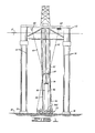
- F-IG. 1 is a schematic elevation view of a tension leg platform located above a subsea wellhead template, with two risers already connected between the tension leg platform and the subsea wellhead template, and with a third adjacent riser being lowered into place with the aid of a splayed guideline system.
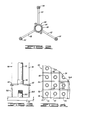
- FIG. 2 is a plan view of a follower means for attachment to a production riser to allow the same to slidably receive three splayed guidelines.
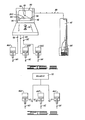
- FIG. 3 is a schematic elevation view of the lower end of a production riser being lowered into engagement with a wellhead on the subsea wellhead template, wherein at least two parallel guidelines are utilized to aid in the positioning of the riser.
- FIG. 4 is the schematic plan view of the subsea wellhead template.
- FIG. 5 is a schematic illustration of a control system utilizing video monitoring of the position of the riser as it is lowered, and utilizing a joystick operator to control the tension being applied to three splayed guidelines by means of hydraulic ram type tensioners.
- FIG. 6 is a schematic illustration of a system providing equal constant tension to the three splayed guidelines.
- Referring now to the drawings, and particularly to FIG. 1, a tension leg platform 10 is thereshown anchored in a body of
water 12 by a plurality oftethering elements 14 attached toanchor bases 16 which are anchored in place on thefloor 18 of the body of water. - A
subsea wellhead template 20 is located on theocean floor 18. - FIG. 4 shows a plan view of a portion of the
subsea wellhead template 20. As is thereshown, thetemplate 20 includes aframework 22 within which is arranged a plurality of regularly spacedwellheads 24. - The
framework 22 also supports a plurality ofguideposts 26 which are generally arranged so that a square pattern of fourguideposts 26 are provided about any one of thewellheads 24. - Referring again to FIG. 1, two
risers subsea wellhead template 20. Athird riser 32 is shown being lowered from the tension leg platform 10 to thewellhead template 20. - Two conventional constantly tensioned parallel guideli-
nes wellhead template 20 on diagonally opposite sides of awellhead 24A to which theriser 32 is to be connected. - For example, referring to FIG. 4, one cf the wellheads thereof has been denoted as 24A for purposes of illustration, and two diagonal guideposts such as 26A and 26B would be utilized to connect the
parallel guidelines guideposts 26 aroundwellhead 24A. - Referring to FIG. 3, a schematic elevation view is thereshown of the
wellhead 24A, theguideposts guidelines parallel guidelines - On the lower end of
riser 32 there is aconventional wellhead connector 38 and conventional follower means 40 and 42 are attached thereto and have the constantly tensionedparallel guidelines wellhead connector 38 into engagement with thewellhead 24A. - Referring again to FIG. 1, a splayed guideline follower means 44 is connected to the
riser 32. An enlarged plan view of splayed guideline follower means 44 is shown in FIG. 2. There it is seen that a central ring 46 is bolted aboutriser 32 and has threearms guideline receivers guideline receivers - Three splayed guidelines, two of which are shown in FIG. 1 and designated as 60 and 62, are connected between the tension leg platform 10 and the
subsea wellhead template 20. Tension leg platform 10 may be referred to as a surface structure, andsubsea wellhead template 20 may be referred to as a fixed structure located within the body ofwater 12 below the tension leg platform 10. - As schematically illustrated in FIG. 5, there are actually preferably three of these splayed guidelines which are designated as 60, 62 and 64. The third splayed
guideline 64 is not visible in FIG. 1 since it is located behind the other equipment which is there illustrated. Also, it is noted that FIG. 1 is a schematic illustration and only two of the splayed guidelines are there shown for ease of illustration. - Each of the splayed
guidelines guideline receivers riser 32. - The exact portion of the
guidelines guidelines riser 32. - The upper ends of the splayed guidelines are attached to a tension means for tensioning the splayed guidelines to exert a lateral force on the
riser 32 as it is being lowered. - The tension means may include various types of guideline tensioners, two of which are schematically illustrated in FIG. 1. A hydraulic
ram type tensioner 66 is shown connected to the upper end of splayedguideline 60. A rotarywinch type tensioner 68 is shown connected to the upper end of splayedguideline 62. It will be understood that generally the same type of tensioner will be utilized for all three of the splayed guidelines, but alternative versions are shown in FIG. 1 merely to prevent unnecessary duplication of drawings. - The hydraulic
ram type tensioner 66 may for example be obtained from the NL Shaffer company or the Vetco company in the form illustrated at pages 4950-4954 and pages 6861-6862, respectively, of the 1978-79 COMPOSITE CATALOG OF OIL FIELD EQUIPMENT & SERVICES. - Depending upon the particular application involved, the splayed
guidelines - FIG. 6 schematically illustrates a system having three hydraulic
ram type tensioners guidelines hydraulic power source 70 is connected by hydraulically parallelfluid supply lines hydraulic ram tensioners 66A, B and C, so that equal constant tension forces are applied to the splayedguidelines - A system providing separately variable guideline tensioners to each of the splayed
guidelines hydraulic ram tensioners - The tension means illustrated in FIG. 5 includes first, second and third separately
variable guideline tensioners guidelines - In connection with the separately variable tension means of FIG. 5, it is desirable to provide a position indicator means for providing an indication at a surface of the body of
water 12 of the position of theriser 32 as it is lowered in relation to adjacent previously positioned subsea equipment such as first andsecond risers TV camera 84 mounted in the lower end ofriser 32 and pointed downward so as to view directly below theriser 32.TV camera 84 is connected to avideo display screen 86 located in a control room on the tension leg platform 10. This connection is provided by electrical connectingmeans 88. - Schematically illustrated as displayed on the
screen 86 is an image of the upper end ofwellhead 24A and of theparallel guidelines riser 32 moves laterally relative to thewellhead 24A, the position of the image ofwellhead 24A andparallel guidelines screen 86 will move on thescreen 86. - The
screen 86 has three fixedtarget lines center point 96 representing the desired location of the image ofwellhead 24A. - The target lines 90, 92 and 94 are arranged at angles of 120° therebetween to represent the orientation of the three splayed
guidelines riser 32. The target lines 90, 92 and 94 may be thought of as corresponding toguidelines - Also, it will be readily apparent that all the adjacent structures such as
subsea wellhead template 20 and therisers screen 86, although they have not been shown in FIG. 5. - A control means 98 is provided for controlling the tension in each of the splayed
guidelines hydraulic ram tensioners - The
center point 96 represents the position of thecamera 84, and thus of the lower end ofriser 32, and thus a human operator working the joystick operator handle 98 will observe the position of the riser relative to surrounding equipment and control the position ofriser 32 by moving the joystick operator handle 98 so that the image ofwellhead 24A coincides withcenter point 96. - Similarly, the television cameras such as 84 could be mounted adjacent the
riser 32 by a framework such as illustrated in U. S. Patent No. 3,215,202 to Pollard et al. so that thescreen 86 will directly display the image of the lower end ofriser 32 and the adjacent surroundings so that the actual engagement ofriser 32 withwellhead 24A could be viewed. - A combination of both types of position indicator systems could be utilized such that one video display screen displays a view such as that illustrated in FIG. 5, and a second screen illustrates a view such as would be provided by a system like that of U. S. Patent No. 3,215,202 to Pollard et al.
- Also, it is possible to use acoustic position indicator systems instead of the video system illustrated in FIG. 5.
- The system just illustrated and described, utilizes three double splayed guidelines located at angles of 120° about the
riser 32. - The preferred embodiment of the invention illustrated in the drawing and just described above has three splayed guidelines. It is necessary to have at least three splayed guidelines to provide complete control of lateral movement of
riser 32 in any horizontal direction. It is of course possible to utilize more than three splayed guidelines. There are, however, situations where only two splayed guidelines may be necessary to achieve the desired positioning. Those would be situations wherein control in only one general horizontal direction was needed. For example, only two splayed guidelines would be required if the current were constantly from only one direction and/or if adjacent risers were only on diametrically opposite sides of a subsea location to which a third riser being lowered is to be connected. - Also, the splayed
guidelines - The principle behind the use of splayed guidelines, as opposed to using parallel guidelines for guiding subsea equipment into place as it is lowered within a body of water, is that greater lateral forces can be applied by the use of splayed guidelines for a given tension present in the guideline. This is a matter of the geometric arrangement of the guidelines. Thus, the actual tension in the splayed guidelines can be reduced as compared to a system which uses only parallel guidelines.
- It is entirely possible in prior art type systems using parallel guidelines, if you are lowering very heavy equipment in hostile environments wherein severe lateral hydrodynamic forces are encountered, that the tension forces which would be necessary to provide sufficient lateral force to control the lateral position of the equipment being lowered would be very much greater than the breaking strength of conventional wire cable guidelines. Thus, guidelines of much greater size than normal, requiring much larger tensioning means would be required.
- Alternatively, if using only parallel guidelines it could become necessary to spread out the locations of the wellheads to allow more tolerance in the lateral position control required.
- Preferably in optimizing the concept of the present invention for any particular application, the angle at which the splayed guidelines are splayed will be arranged such that wire cable guidelines of conventional sizes, in a range of about 5/8 to 3/4 inch diameter, can be utilized with only a single conventional hydraulic ram type tensioner provided on each splayed guideline to provide sufficient lateral forces for the necessary lateral positioning control.
- Thus it is seen that the apparatus and methods of the present invention readily achieve the ends and advantages mentioned as well as those inherent therein. While certain preferred embodiments of the present invention have been illustrated for the purposes of the present disclosure, numerous changes in the arrangement and construction of parts and steps may be made by those skilled in the art, which changes are encompassed within the scope this invention as defined by the appended claims.
Claims (21)
Applications Claiming Priority (2)
| Application Number | Priority Date | Filing Date | Title |
|---|---|---|---|
| US346854 | 1982-02-08 | ||
| US06/346,854 US4451177A (en) | 1982-02-08 | 1982-02-08 | Guideline system for positioning subsea equipment |
Publications (3)
| Publication Number | Publication Date |
|---|---|
| EP0086099A2 true EP0086099A2 (en) | 1983-08-17 |
| EP0086099A3 EP0086099A3 (en) | 1984-05-16 |
| EP0086099B1 EP0086099B1 (en) | 1988-08-17 |
Family
ID=23361302
Family Applications (1)
| Application Number | Title | Priority Date | Filing Date |
|---|---|---|---|
| EP83300581A Expired EP0086099B1 (en) | 1982-02-08 | 1983-02-04 | Guideline system for positioning subsea equipment |
Country Status (6)
| Country | Link |
|---|---|
| US (1) | US4451177A (en) |
| EP (1) | EP0086099B1 (en) |
| JP (1) | JPS58156615A (en) |
| CA (1) | CA1187868A (en) |
| DK (1) | DK153931C (en) |
| NO (1) | NO830380L (en) |
Families Citing this family (4)
| Publication number | Priority date | Publication date | Assignee | Title |
|---|---|---|---|---|
| NL2006982C2 (en) * | 2011-06-22 | 2013-01-02 | Ihc Holland Ie Bv | Centre system. |
| CA2784850C (en) | 2012-07-30 | 2015-11-24 | Jeremy Leonard | Method of automated variable speed control of movement of a cutter head of a dredging cutter |
| CA2784630C (en) | 2012-07-30 | 2015-07-07 | Jeremy Leonard | Method of dredging a pond |
| CA3004270C (en) | 2018-05-08 | 2022-01-25 | Jeremy Leonard | Autonomous vertically-adjustable dredge |
Family Cites Families (15)
| Publication number | Priority date | Publication date | Assignee | Title |
|---|---|---|---|---|
| US3032125A (en) * | 1957-07-10 | 1962-05-01 | Jersey Prod Res Co | Offshore apparatus |
| US3021909A (en) * | 1958-10-01 | 1962-02-20 | California Research Corp | Means for offshore drilling |
| US3129774A (en) * | 1960-09-09 | 1964-04-21 | California Research Corp | Method and apparatus for drilling and working in offshore wells |
| US3215202A (en) * | 1961-10-10 | 1965-11-02 | Richfield Oil Corp | Off-shore drilling and production apparatus |
| US3209827A (en) * | 1962-09-13 | 1965-10-05 | Shell Oil Co | Well drilling method and apparatus |
| US3333820A (en) * | 1966-05-17 | 1967-08-01 | Moore Corp Lee C | Oil well drilling apparatus with traveling block guide |
| FR1498353A (en) * | 1966-05-25 | 1967-10-20 | Grenobloise Etude Appl | Mooring system for floating bodies, in particular for wharfs |
| US3458853A (en) * | 1967-08-08 | 1969-07-29 | Eg & G Inc | Underwater guidance method and apparatus |
| US3430695A (en) * | 1967-11-08 | 1969-03-04 | Mobil Oil Corp | Method and apparatus for installing underwater wellhead support |
| FR2242290B1 (en) * | 1973-09-03 | 1977-02-25 | Subsea Equipment Ass Ltd | |
| US4181453A (en) * | 1977-08-24 | 1980-01-01 | Sea Tank Co. | Apparatus for positioning an off-shore weight structure on a previously positioned sea bed unit |
| US4192383A (en) * | 1978-05-02 | 1980-03-11 | Armco Inc. | Offshore multiple well drilling and production apparatus |
| US4226555A (en) * | 1978-12-08 | 1980-10-07 | Conoco, Inc. | Mooring system for tension leg platform |
| US4260291A (en) * | 1979-02-27 | 1981-04-07 | J. Ray Mcdermott & Co., Inc. | Installation of an offshore structure |
| US4273471A (en) * | 1979-06-13 | 1981-06-16 | Chevron Research Company | Marine-drilling sub-base assembly for a soft-bottom foundation |
-
1982
- 1982-02-08 US US06/346,854 patent/US4451177A/en not_active Expired - Fee Related
-
1983
- 1983-01-28 CA CA000420514A patent/CA1187868A/en not_active Expired
- 1983-02-04 EP EP83300581A patent/EP0086099B1/en not_active Expired
- 1983-02-04 DK DK046683A patent/DK153931C/en not_active IP Right Cessation
- 1983-02-04 NO NO830380A patent/NO830380L/en unknown
- 1983-02-07 JP JP58017597A patent/JPS58156615A/en active Pending
Also Published As
| Publication number | Publication date |
|---|---|
| NO830380L (en) | 1983-08-09 |
| DK46683A (en) | 1983-08-09 |
| JPS58156615A (en) | 1983-09-17 |
| DK153931C (en) | 1989-02-06 |
| US4451177A (en) | 1984-05-29 |
| EP0086099B1 (en) | 1988-08-17 |
| EP0086099A3 (en) | 1984-05-16 |
| CA1187868A (en) | 1985-05-28 |
| DK153931B (en) | 1988-09-26 |
| DK46683D0 (en) | 1983-02-04 |
Similar Documents
| Publication | Publication Date | Title |
|---|---|---|
| DE69915616T2 (en) | Apparatus and method for settling an object or a load on the seabed | |
| EP2420439B1 (en) | Method for lowering an object to an underwater installation site using a ROV | |
| US4611662A (en) | Remotely operable releasable pipe connector | |
| EP3735509B1 (en) | Integrating wells in towable subsea units | |
| CN102834583A (en) | Subsea orientation and control system | |
| GB2326758A (en) | Weighted subsea control cable | |
| US4363566A (en) | Flow line bundle and method of towing same | |
| GB2226063A (en) | Production system for subsea oil wells | |
| US3179176A (en) | Method and apparatus for carrying out operations at underwater installations | |
| US4710061A (en) | Offshore well apparatus and method | |
| US4451177A (en) | Guideline system for positioning subsea equipment | |
| US4430023A (en) | Rope guiding device | |
| GB2069955A (en) | Anchoring apparatus for a ship used in the production of hydrocarbons | |
| EP0045652A2 (en) | Mooring of floating structures | |
| EP2690249A1 (en) | Intervention workover control systems | |
| EP0045651A2 (en) | Apparatus and method for supporting a tubular riser | |
| GB1582950A (en) | Submersible pipe installation systems | |
| US3225826A (en) | Method and apparatus for working on submerged wells | |
| EP0981680B1 (en) | A connection device | |
| EP0058159B1 (en) | Rope guiding device | |
| US10794139B2 (en) | Umbilical method | |
| CA2129563C (en) | Interface system for operation of remote control vehicle | |
| GB1599198A (en) | Providing a continuous fluid flow path from a submerged pipeline to an offshore apparatus | |
| EP0045653B1 (en) | Mooring of floating structures | |
| US3696864A (en) | Undersea riser structure |
Legal Events
| Date | Code | Title | Description |
|---|---|---|---|
| PUAI | Public reference made under article 153(3) epc to a published international application that has entered the european phase |
Free format text: ORIGINAL CODE: 0009012 |
|
| AK | Designated contracting states |
Designated state(s): FR GB NL |
|
| PUAL | Search report despatched |
Free format text: ORIGINAL CODE: 0009013 |
|
| AK | Designated contracting states |
Designated state(s): FR GB NL |
|
| 17P | Request for examination filed |
Effective date: 19840716 |
|
| 17Q | First examination report despatched |
Effective date: 19860305 |
|
| GRAA | (expected) grant |
Free format text: ORIGINAL CODE: 0009210 |
|
| AK | Designated contracting states |
Kind code of ref document: B1 Designated state(s): FR GB NL |
|
| ET | Fr: translation filed | ||
| PLBE | No opposition filed within time limit |
Free format text: ORIGINAL CODE: 0009261 |
|
| STAA | Information on the status of an ep patent application or granted ep patent |
Free format text: STATUS: NO OPPOSITION FILED WITHIN TIME LIMIT |
|
| 26N | No opposition filed | ||
| PGFP | Annual fee paid to national office [announced via postgrant information from national office to epo] |
Ref country code: GB Payment date: 19910116 Year of fee payment: 9 |
|
| PGFP | Annual fee paid to national office [announced via postgrant information from national office to epo] |
Ref country code: FR Payment date: 19910219 Year of fee payment: 9 |
|
| PGFP | Annual fee paid to national office [announced via postgrant information from national office to epo] |
Ref country code: NL Payment date: 19910228 Year of fee payment: 9 |
|
| PG25 | Lapsed in a contracting state [announced via postgrant information from national office to epo] |
Ref country code: GB Effective date: 19920204 |
|
| PG25 | Lapsed in a contracting state [announced via postgrant information from national office to epo] |
Ref country code: NL Effective date: 19920901 |
|
| GBPC | Gb: european patent ceased through non-payment of renewal fee | ||
| NLV4 | Nl: lapsed or anulled due to non-payment of the annual fee | ||
| PG25 | Lapsed in a contracting state [announced via postgrant information from national office to epo] |
Ref country code: FR Effective date: 19921030 |
|
| REG | Reference to a national code |
Ref country code: FR Ref legal event code: ST |