EP0085508A2 - Metal halogen battery - Google Patents
Metal halogen battery Download PDFInfo
- Publication number
- EP0085508A2 EP0085508A2 EP83300271A EP83300271A EP0085508A2 EP 0085508 A2 EP0085508 A2 EP 0085508A2 EP 83300271 A EP83300271 A EP 83300271A EP 83300271 A EP83300271 A EP 83300271A EP 0085508 A2 EP0085508 A2 EP 0085508A2
- Authority
- EP
- European Patent Office
- Prior art keywords
- halogen
- electrolyte
- sump
- store
- battery
- Prior art date
- Legal status (The legal status is an assumption and is not a legal conclusion. Google has not performed a legal analysis and makes no representation as to the accuracy of the status listed.)
- Granted
Links
Images
Classifications
-
- H—ELECTRICITY
- H01—ELECTRIC ELEMENTS
- H01M—PROCESSES OR MEANS, e.g. BATTERIES, FOR THE DIRECT CONVERSION OF CHEMICAL ENERGY INTO ELECTRICAL ENERGY
- H01M8/00—Fuel cells; Manufacture thereof
- H01M8/04—Auxiliary arrangements, e.g. for control of pressure or for circulation of fluids
-
- B—PERFORMING OPERATIONS; TRANSPORTING
- B60—VEHICLES IN GENERAL
- B60L—PROPULSION OF ELECTRICALLY-PROPELLED VEHICLES; SUPPLYING ELECTRIC POWER FOR AUXILIARY EQUIPMENT OF ELECTRICALLY-PROPELLED VEHICLES; ELECTRODYNAMIC BRAKE SYSTEMS FOR VEHICLES IN GENERAL; MAGNETIC SUSPENSION OR LEVITATION FOR VEHICLES; MONITORING OPERATING VARIABLES OF ELECTRICALLY-PROPELLED VEHICLES; ELECTRIC SAFETY DEVICES FOR ELECTRICALLY-PROPELLED VEHICLES
- B60L50/00—Electric propulsion with power supplied within the vehicle
- B60L50/50—Electric propulsion with power supplied within the vehicle using propulsion power supplied by batteries or fuel cells
- B60L50/60—Electric propulsion with power supplied within the vehicle using propulsion power supplied by batteries or fuel cells using power supplied by batteries
- B60L50/64—Constructional details of batteries specially adapted for electric vehicles
-
- H—ELECTRICITY
- H01—ELECTRIC ELEMENTS
- H01M—PROCESSES OR MEANS, e.g. BATTERIES, FOR THE DIRECT CONVERSION OF CHEMICAL ENERGY INTO ELECTRICAL ENERGY
- H01M10/00—Secondary cells; Manufacture thereof
- H01M10/36—Accumulators not provided for in groups H01M10/05-H01M10/34
- H01M10/365—Zinc-halogen accumulators
-
- H—ELECTRICITY
- H01—ELECTRIC ELEMENTS
- H01M—PROCESSES OR MEANS, e.g. BATTERIES, FOR THE DIRECT CONVERSION OF CHEMICAL ENERGY INTO ELECTRICAL ENERGY
- H01M10/00—Secondary cells; Manufacture thereof
- H01M10/42—Methods or arrangements for servicing or maintenance of secondary cells or secondary half-cells
- H01M10/4214—Arrangements for moving electrodes or electrolyte
-
- Y—GENERAL TAGGING OF NEW TECHNOLOGICAL DEVELOPMENTS; GENERAL TAGGING OF CROSS-SECTIONAL TECHNOLOGIES SPANNING OVER SEVERAL SECTIONS OF THE IPC; TECHNICAL SUBJECTS COVERED BY FORMER USPC CROSS-REFERENCE ART COLLECTIONS [XRACs] AND DIGESTS
- Y02—TECHNOLOGIES OR APPLICATIONS FOR MITIGATION OR ADAPTATION AGAINST CLIMATE CHANGE
- Y02E—REDUCTION OF GREENHOUSE GAS [GHG] EMISSIONS, RELATED TO ENERGY GENERATION, TRANSMISSION OR DISTRIBUTION
- Y02E60/00—Enabling technologies; Technologies with a potential or indirect contribution to GHG emissions mitigation
- Y02E60/10—Energy storage using batteries
-
- Y—GENERAL TAGGING OF NEW TECHNOLOGICAL DEVELOPMENTS; GENERAL TAGGING OF CROSS-SECTIONAL TECHNOLOGIES SPANNING OVER SEVERAL SECTIONS OF THE IPC; TECHNICAL SUBJECTS COVERED BY FORMER USPC CROSS-REFERENCE ART COLLECTIONS [XRACs] AND DIGESTS
- Y02—TECHNOLOGIES OR APPLICATIONS FOR MITIGATION OR ADAPTATION AGAINST CLIMATE CHANGE
- Y02E—REDUCTION OF GREENHOUSE GAS [GHG] EMISSIONS, RELATED TO ENERGY GENERATION, TRANSMISSION OR DISTRIBUTION
- Y02E60/00—Enabling technologies; Technologies with a potential or indirect contribution to GHG emissions mitigation
- Y02E60/30—Hydrogen technology
- Y02E60/50—Fuel cells
-
- Y—GENERAL TAGGING OF NEW TECHNOLOGICAL DEVELOPMENTS; GENERAL TAGGING OF CROSS-SECTIONAL TECHNOLOGIES SPANNING OVER SEVERAL SECTIONS OF THE IPC; TECHNICAL SUBJECTS COVERED BY FORMER USPC CROSS-REFERENCE ART COLLECTIONS [XRACs] AND DIGESTS
- Y02—TECHNOLOGIES OR APPLICATIONS FOR MITIGATION OR ADAPTATION AGAINST CLIMATE CHANGE
- Y02T—CLIMATE CHANGE MITIGATION TECHNOLOGIES RELATED TO TRANSPORTATION
- Y02T10/00—Road transport of goods or passengers
- Y02T10/60—Other road transportation technologies with climate change mitigation effect
- Y02T10/70—Energy storage systems for electromobility, e.g. batteries
Definitions
- the present invention relates to an improved metal halogen battery construction.
- the arrangement disclosed herein is particularly useful for mobile battery applications, e.g. for electric vehicles.
- the electrical energy storage systems of the type referred to herein utilize a halogen hydrate as the source of a halogen component for reduction at a normally positive electrode, and an oxidizable metal adapted to become oxidized at a normally negative electrode during the normal discharge of the storage system.
- An aqueous electrolyte is employed for replenishing the supply of the halogen component as it becomes reduced at the positive electrode.
- the electrolyte contains the dissolved ions of the oxidized metal and the reduced halogen and is circulated between the electrode area and a storage area containing halogen hydrate which progressively decomposes during a normal discharge of the electrical energy system, liberating additional elemental halogen to be consumed at the positive electrode.
- Electrical energy storage systems or battery systems of this type are described in our prior U.S. patents Nos. 3,713,888, 3,993,502, 4,001,036, 4,072,540 and 4,146,680. Such systems are also described in published reports such as "Zinc-Chloride Electric Engine Unit for Four Passenger Electric Vehicle" by J. Kiwalle and J. Galloway of Energy Development Associates, and EPRI Report EM-1051 (Parts 1-3) dated April 1979, published by the Electric Power Research Institute.
- an electrolyte pump delivers aqueous electrolyte to pockets between pairs of porous graphite-chlorine electrodes in a battery stack.
- the electrolyte passes through the porous chlorine electrodes into a chamber between electrodes of opposite polarity, flows up between the electrodes,then flows back into the battery sump.
- Chlorine gas liberated from porous graphite electrode substrates is pumped by a gas pump, and before entering the gas pump, the chlorine is mixed with electrolyte chilled by a chiller unit.
- the chlorine and chilled electrolyte are mixed in the gas pump, chlorine hydrate forms, and the chlorine hydrate- electrolyte mixture is deposited in the store.
- a metal halogen battery construction comprising at least one cell having a positive electrode and a negative electrode for contact with aqueous electrolyte containing the material of said metal and halogen, a sump wherein the electrolyte is collected, a store wherein halogen hydrate is formed and stored as part of an aqueous material, circulation means for transmitting electrolyte through the battery, and conduit means for transmitting halogen gas formed in the cell to hydrate forming means associated with the store, characterised in that fluid jet pump means is provided operative to cause circulation of gases including hydrogen and halogen from the sump to contact a reactor means whereby hydrogen and halogen are combined and returned to the sump.
- Another aspect of the invention includes a special pressure sensitive valve or diaphragm valve which uniquely controls the distribution of chlorine from the battery store to the stack.
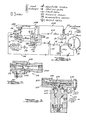
- FIG 1 illustrates a schematic view of a zinc-chlorine battery system wherein means are provided to achieve the desired flows of chlorine, electrolyte, and heat.
- the zinc-chloride battery consists of three basic parts, the stack, the sump, and the store, as shown in Figure 1.
- the stack 10 consists of a plurality of cells made up, for example, of solid-graphite zinc electrodes and porous-graphite chlorine electrodes. Each cell has the potential of two volts (thus giving a stack arrangement with 60 cells a 120-volt potential).
- Sump means 20 is comprised of an electrolyte reservoir 22 and an electrolyte pump P-1 to circulate the electrolyte 21.
- Store means 30 contains a gas pump P-2 and a filter means 32.
- the store functions to store the chlorine reactant in the form of chlorine hydrate, which is a brilliant yellow solid that decomposes to chlorine gas and electrolyte at temperatures above 9.6°C at ambient atmospheric pressure.
- the centrifugal pump P-I circulates the electrolyte 21 from the reservoir 22 to the individual porous electrodes (not shown) in the stack through the conduit 24, from which electrolyte returns to the reservoir through the conduit 25.
- the small quantity of hydrogen evolved during battery operation is combined with the chlorine in an ultraviolet light-activated reactor 40 to form hydrogen chloride, which is subsequently returned to the electrolyte reservoir as will be described herein.
- a jet pump construction 50 is employed.
- a small quantity of electrolyte from electrolyte pump P-1 is diverted into the jet pump 50 through the conduits 51, 52 to act as a driving force for the jet pump.
- the jet pump 50 is also shown in more detail in Figure 2.
- the stream of liquid electrolyte passing through the jet pump from conduit 52 causes a suction whereby the gases from the reservoir 22 and from the upper part of the reactor 40 are drawn into the jet pump through the conduit 501, and the gases are then mixed in with the liquid stream exiting from the nozzle 502 near the point 503. Thereafter the intermixture of gas and liquid is returned to the sump 20 via the conduit 504.
- the heat exchanger HX-1 operates to provide cooling for the electrolyte in the sump during operation of the battery.
- This chilled electrolyte contacts chlorine gas (via conduit 54) drawn from the stack by the vacuum at the intake 56 to the gas pump P-2, and chlorine hydrate is formed at the outlet port of pump P-2. Hydrate is filtered-out in the store in a fashion similar to a filtering press by the filter means 32.
- the formation of chlorine hydrate from the aqueous electrolyte leads to an increasing concentration of zinc chloride within the store 30, and the electrolysis of the zinc chloride in the stack 10 reduces the zinc-chloride concentration in it. Therefore, by interchanging electrolyte between the stack and store, the use of zinc chloride is optimized in the system.
- the electrolyte interchange between the stack 10 and store 30 is accomplished by pumping warm electrolyte (30°C) via the centrifugal pump P-1 and conduit 55 from the sump reservoir 22 in the store 30, and returning cold electrolyte (0°C) through conduit 57 from the store 30 to the stack at point 58 on the high pressure side of pump P-1, and then via conduit 24 to the stack 10. The flow rates of both solutions are approximately equal.
- conduit 57 If the fluid flow pressure in conduit 57 exceeds approximately 25 psia (1.7 bar) then the fluid by-passes valve 60 and flows through the relief valve 90 to conduit 614 which leads to the high pressure side of the electrolyte pump P-1 at point 58.
- System pressure during charge represents a balance between the rate of chlorine generation and the rate of hydrate formation. Therefore, when the stack pressure increases above a predetermined level, more coolant is required for hydrate formation and vice versa.
- a diaphragm operated, 2-position-unidirectional flow valve is utilized as designated at 60 with the valve being normally in the closed position.
- This pressure sensitive valve 60 is also shown in more detail in Figure 3.
- the valve is constructed as a variant of spool valve, and it provides for close control of chlorine demand and bubble tight isolation of the store from the stack. A large demand of power from the battery will result in a large demand of chlorine, and this will lower the pressure in the reservoir 22.
- the reservoir pressure is fed to the valve 60 through the conduit 602.
- the diaphragm 604 of the valve 60 is acted upon by reservoir pressure on side 606 of the diaphragm, and ambient atmospheric pressure operates against the other side 608, with the side 608 being connected to atmosphere through conduit 610 (Fig.3).
- Lowering of the pressure in reservoir 22 below ambient atmospheric pressure causes opening of the valve 60, due to lifting of the diaphragm member 604 which is connected to valve spool 612, and this allows chlorine from the store via conduit 57 to be transmitted through conduit 614 to the discharge side of pump P-1 at point 58.
- valve 60 shuts tight due to operation of the store fluid pressure on valve surface 616. Further increase of the store pressure shuts the valve 60 tighter.
- the valve can also be biased to operate at a pressure higher than ambient atmospheric pressure, so that whole system would work above ambient atmospheric pressure; and for example, this can be done by attaching a suitable spring biasing member to one end of the spool if it is desired to operate the system at higher than ambient atmospheric pressure.
- the battery system described herein has been found to work in a very advantageous and satisfactory manner.
- the novel jet pump technique utilizing aqueous electrolyte to pump gas, as disclosed herein eliminates the need to run the gas pump continuously during the discharge cycle of the battery, and this results in less power dissipation and better battery efficiency.
- the novel pressure sensitive valve construction disclosed herein can be operated by sump atmospheric pressure against ambient atmospheric pressure, or it can be operated against pressureshigher than ambient atmospheric pressure through use of spring biasing, such that the whole system would be workable above ambient atmospheric pressure.
- This valve construction is highly advantageous in that it provides the capability to isolate the store from the sump, and when sump pressure drops below the setting of the valve, the valve opens and allows chlorine from the store to be discharged into the sump. Upon reaching the valve setting, the valve closes and any increased store pressure shuts the valve tighter. Usage of this valve has resulted in less power dissipation and increased battery efficiency.
- the battery system disclosed herein has been used to power a full size 4-door automobile and it has performed very satisfactorily in numerous miles of test driving.
Landscapes
- Engineering & Computer Science (AREA)
- Chemical Kinetics & Catalysis (AREA)
- Manufacturing & Machinery (AREA)
- General Chemical & Material Sciences (AREA)
- Electrochemistry (AREA)
- Chemical & Material Sciences (AREA)
- Sustainable Energy (AREA)
- Life Sciences & Earth Sciences (AREA)
- Sustainable Development (AREA)
- Power Engineering (AREA)
- Transportation (AREA)
- Mechanical Engineering (AREA)
- Hybrid Cells (AREA)
- Secondary Cells (AREA)
- Supply Devices, Intensifiers, Converters, And Telemotors (AREA)
- Sealing Battery Cases Or Jackets (AREA)
- Primary Cells (AREA)
- Battery Electrode And Active Subsutance (AREA)
Abstract
Description
- The present invention relates to an improved metal halogen battery construction. The arrangement disclosed herein is particularly useful for mobile battery applications, e.g. for electric vehicles.
- The electrical energy storage systems of the type referred to herein (e.g. a zinc-chlorine battery system) utilize a halogen hydrate as the source of a halogen component for reduction at a normally positive electrode, and an oxidizable metal adapted to become oxidized at a normally negative electrode during the normal discharge of the storage system. An aqueous electrolyte is employed for replenishing the supply of the halogen component as it becomes reduced at the positive electrode. The electrolyte contains the dissolved ions of the oxidized metal and the reduced halogen and is circulated between the electrode area and a storage area containing halogen hydrate which progressively decomposes during a normal discharge of the electrical energy system, liberating additional elemental halogen to be consumed at the positive electrode. Electrical energy storage systems or battery systems of this type are described in our prior U.S. patents Nos. 3,713,888, 3,993,502, 4,001,036, 4,072,540 and 4,146,680. Such systems are also described in published reports such as "Zinc-Chloride Electric Engine Unit for Four Passenger Electric Vehicle" by J. Kiwalle and J. Galloway of Energy Development Associates, and EPRI Report EM-1051 (Parts 1-3) dated April 1979, published by the Electric Power Research Institute.
- The basic operation of a zinc-chloride battery system is as follows. During charging, an electrolyte pump delivers aqueous electrolyte to pockets between pairs of porous graphite-chlorine electrodes in a battery stack. The electrolyte passes through the porous chlorine electrodes into a chamber between electrodes of opposite polarity, flows up between the electrodes,then flows back into the battery sump. Chlorine gas liberated from porous graphite electrode substrates is pumped by a gas pump, and before entering the gas pump, the chlorine is mixed with electrolyte chilled by a chiller unit. The chlorine and chilled electrolyte are mixed in the gas pump, chlorine hydrate forms, and the chlorine hydrate- electrolyte mixture is deposited in the store. During discharge, chlorine is liberated from hydrate by decomposition of chlorine hydrate in the store by injection of warm electrolyte from the sump. On development of the required chlorine gas pressure in the store, the chlorine is injected and mixed with and dissolved in the electrolyte, which is then fed to the porous electrodes in the battery stack. The battery stack is then discharged, wherein electrode dissolution of zinc occurs at the zinc electrode, reduction of the dissolved chlorine occurs at the chlorine electrode, power is available from the battery terminals, and zinc chloride is formed in the electrolyte by reaction of zinc and chlorine to form zinc chloride.
- There have been certain weaknesses or disadvantages in prior experimental systems directed towards a metal halogen battery system for mobile applications. For example, power dissipation has occurred in such systems because it was necessary to run the gas pump essentially, or at least substantially, continuously during discharge. Secondly, the pressure differential between the store and the sump was set by a pressure differential valve, which meant that if the store pressure changed, then sump pressure would follow whereas sump pressure should normally be kept close to atmospheric pressure.
- Accordingly it is the main object of this invention to provide a novel and improved metal halogen battery system for mobile applications.
- According to this invention there is provided a metal halogen battery construction comprising at least one cell having a positive electrode and a negative electrode for contact with aqueous electrolyte containing the material of said metal and halogen, a sump wherein the electrolyte is collected, a store wherein halogen hydrate is formed and stored as part of an aqueous material, circulation means for transmitting electrolyte through the battery, and conduit means for transmitting halogen gas formed in the cell to hydrate forming means associated with the store, characterised in that fluid jet pump means is provided operative to cause circulation of gases including hydrogen and halogen from the sump to contact a reactor means whereby hydrogen and halogen are combined and returned to the sump.
- Another aspect of the invention includes a special pressure sensitive valve or diaphragm valve which uniquely controls the distribution of chlorine from the battery store to the stack.
- The invention will become further apparent from the following description given by way of example with reference to the accompanying drawings, wherein:
- FIGURE 1 illustrates a schematic of a battery system in accordance with the invention;
- FIGURE 2 illustrates an embodiment of a jet pump for use in the system of FIG. 1; and
- FIGURE 3 illustrates a special valve means used in the system of FIG. 1.
- Figure 1 illustrates a schematic view of a zinc-chlorine battery system wherein means are provided to achieve the desired flows of chlorine, electrolyte, and heat. The zinc-chloride battery consists of three basic parts, the stack, the sump, and the store, as shown in Figure 1. The
stack 10 consists of a plurality of cells made up, for example, of solid-graphite zinc electrodes and porous-graphite chlorine electrodes. Each cell has the potential of two volts (thus giving a stack arrangement with 60 cells a 120-volt potential). Sump means 20 is comprised of anelectrolyte reservoir 22 and an electrolyte pump P-1 to circulate theelectrolyte 21. Store means 30 contains a gas pump P-2 and a filter means 32. The store functions to store the chlorine reactant in the form of chlorine hydrate, which is a brilliant yellow solid that decomposes to chlorine gas and electrolyte at temperatures above 9.6°C at ambient atmospheric pressure. - The centrifugal pump P-I circulates the
electrolyte 21 from thereservoir 22 to the individual porous electrodes (not shown) in the stack through theconduit 24, from which electrolyte returns to the reservoir through theconduit 25. The small quantity of hydrogen evolved during battery operation is combined with the chlorine in an ultraviolet light-activatedreactor 40 to form hydrogen chloride, which is subsequently returned to the electrolyte reservoir as will be described herein. - As shown, there are two locations of ultraviolet lights, one inside the reservoir gas space indicated at 41, with the U.V. light 41 being activated during charge only; and two more U. V. lights inside
reactor 40 which are activated both during charge and discharge of the battery. In order to generate suction within thereactor 40 necessary to induce flow of gas fromreservoir 22 into thereactor 40 and back intoreservoir 22, ajet pump construction 50 is employed. A small quantity of electrolyte from electrolyte pump P-1 is diverted into thejet pump 50 through theconduits jet pump 50 is also shown in more detail in Figure 2. When the electrolyte pump P-1 is in operation, the stream of liquid electrolyte passing through the jet pump fromconduit 52 causes a suction whereby the gases from thereservoir 22 and from the upper part of thereactor 40 are drawn into the jet pump through theconduit 501, and the gases are then mixed in with the liquid stream exiting from thenozzle 502 near thepoint 503. Thereafter the intermixture of gas and liquid is returned to the sump 20 via theconduit 504. - During charge of the battery system, chlorine is liberated from the porous-graphite chlorine electrode substrates, while zinc is deposited on the solid-graphite electrodes. The chlorine which is liberated in the
stack 10 is subsequently drawn throughconduit 54 to the store 30 via the vacuum created by the gas pump P-2 within the store 30. Such reduced pressure operation lowers the concentration of dissolved chlorine in the stack compartment thereby improving coulombic efficiency. The heat exchanger HX-1 operates to provide cooling for the electrolyte in the sump during operation of the battery. - A small amount of electrolyte, from the output of the centrifugal pump P-l, is also diverted through conduit 55 to heat exchanger HX-2 and chilled to approximately 0°C. This chilled electrolyte contacts chlorine gas (via conduit 54) drawn from the stack by the vacuum at the
intake 56 to the gas pump P-2, and chlorine hydrate is formed at the outlet port of pump P-2. Hydrate is filtered-out in the store in a fashion similar to a filtering press by the filter means 32. - The formation of chlorine hydrate from the aqueous electrolyte leads to an increasing concentration of zinc chloride within the store 30, and the electrolysis of the zinc chloride in the
stack 10 reduces the zinc-chloride concentration in it. Therefore, by interchanging electrolyte between the stack and store, the use of zinc chloride is optimized in the system. The electrolyte interchange between thestack 10 and store 30 is accomplished by pumping warm electrolyte (30°C) via the centrifugal pump P-1 and conduit 55 from thesump reservoir 22 in the store 30, and returning cold electrolyte (0°C) throughconduit 57 from the store 30 to the stack at point 58 on the high pressure side of pump P-1, and then viaconduit 24 to thestack 10. The flow rates of both solutions are approximately equal. If the fluid flow pressure inconduit 57 exceeds approximately 25 psia (1.7 bar) then the fluid by-passes valve 60 and flows through therelief valve 90 to conduit 614 which leads to the high pressure side of the electrolyte pump P-1 at point 58. - System pressure during charge represents a balance between the rate of chlorine generation and the rate of hydrate formation. Therefore, when the stack pressure increases above a predetermined level, more coolant is required for hydrate formation and vice versa.
- During discharge, drop in pressure inside store 30 starts gear pump P-2 injecting warm electrolyte from the reservoir (through pump P-1, conduit 55 and HX-2) until desired store pressure is restored. This action decomposes a portion of the chlorine hydrate within the store, thereby liberating chlorine and increasing the internal pressure in the store. This chlorine is injected into the discharge port of the centrifugal pump P-1 at point 58, and then circulated through the stack. Control is maintained by monitoring the pressure of the store, which indicates the balance between the rate of chlorine consumption in the stack and the rate of chlorine decomposition in the store. This, in turn, is controlled by the rate of injecting warm electrolyte into the store.
- The demand for power from the battery can change rapidly but due to the large thermal mass within the store, evolution of chlorine tracks demand only approximately. Therefore a diaphragm operated, 2-position-unidirectional flow valve is utilized as designated at 60 with the valve being normally in the closed position. This pressure
sensitive valve 60 is also shown in more detail in Figure 3. The valve is constructed as a variant of spool valve, and it provides for close control of chlorine demand and bubble tight isolation of the store from the stack. A large demand of power from the battery will result in a large demand of chlorine, and this will lower the pressure in thereservoir 22. The reservoir pressure is fed to thevalve 60 through theconduit 602. The diaphragm 604 of thevalve 60 is acted upon by reservoir pressure onside 606 of the diaphragm, and ambient atmospheric pressure operates against theother side 608, with theside 608 being connected to atmosphere through conduit 610 (Fig.3). Lowering of the pressure inreservoir 22 below ambient atmospheric pressure causes opening of thevalve 60, due to lifting of the diaphragm member 604 which is connected tovalve spool 612, and this allows chlorine from the store viaconduit 57 to be transmitted throughconduit 614 to the discharge side of pump P-1 at point 58. When store pressure exceeds ambient atmospheric pressure,valve 60 shuts tight due to operation of the store fluid pressure onvalve surface 616. Further increase of the store pressure shuts thevalve 60 tighter. - The valve can also be biased to operate at a pressure higher than ambient atmospheric pressure, so that whole system would work above ambient atmospheric pressure; and for example, this can be done by attaching a suitable spring biasing member to one end of the spool if it is desired to operate the system at higher than ambient atmospheric pressure.
- The battery system described herein has been found to work in a very advantageous and satisfactory manner. The novel jet pump technique utilizing aqueous electrolyte to pump gas, as disclosed herein eliminates the need to run the gas pump continuously during the discharge cycle of the battery, and this results in less power dissipation and better battery efficiency. The novel pressure sensitive valve construction disclosed herein can be operated by sump atmospheric pressure against ambient atmospheric pressure, or it can be operated against pressureshigher than ambient atmospheric pressure through use of spring biasing, such that the whole system would be workable above ambient atmospheric pressure. This valve construction is highly advantageous in that it provides the capability to isolate the store from the sump, and when sump pressure drops below the setting of the valve, the valve opens and allows chlorine from the store to be discharged into the sump. Upon reaching the valve setting, the valve closes and any increased store pressure shuts the valve tighter. Usage of this valve has resulted in less power dissipation and increased battery efficiency.
- The battery system disclosed herein has been used to power a full size 4-door automobile and it has performed very satisfactorily in numerous miles of test driving.
Claims (6)
Priority Applications (1)
| Application Number | Priority Date | Filing Date | Title |
|---|---|---|---|
| AT83300271T ATE34638T1 (en) | 1982-01-29 | 1983-01-19 | METAL HALOGEN BATTERY. |
Applications Claiming Priority (2)
| Application Number | Priority Date | Filing Date | Title |
|---|---|---|---|
| US343904 | 1982-01-29 | ||
| US06/343,904 US4414292A (en) | 1982-01-29 | 1982-01-29 | Metal halogen battery system |
Publications (3)
| Publication Number | Publication Date |
|---|---|
| EP0085508A2 true EP0085508A2 (en) | 1983-08-10 |
| EP0085508A3 EP0085508A3 (en) | 1984-08-22 |
| EP0085508B1 EP0085508B1 (en) | 1988-05-25 |
Family
ID=23348177
Family Applications (1)
| Application Number | Title | Priority Date | Filing Date |
|---|---|---|---|
| EP83300271A Expired EP0085508B1 (en) | 1982-01-29 | 1983-01-19 | Metal halogen battery |
Country Status (7)
| Country | Link |
|---|---|
| US (1) | US4414292A (en) |
| EP (1) | EP0085508B1 (en) |
| JP (1) | JPS58133787A (en) |
| AT (1) | ATE34638T1 (en) |
| CA (1) | CA1187932A (en) |
| DE (1) | DE3376786D1 (en) |
| MX (1) | MX160534A (en) |
Cited By (2)
| Publication number | Priority date | Publication date | Assignee | Title |
|---|---|---|---|---|
| EP0089754B1 (en) * | 1982-03-12 | 1986-12-10 | Energy Development Associates Inc. | Halogen hydrate storage device in metal halogen battery system |
| SG117433A1 (en) * | 2002-02-21 | 2005-12-29 | Ntt Docomo Inc | Transmission control apparatus and transmission control method |
Families Citing this family (19)
| Publication number | Priority date | Publication date | Assignee | Title |
|---|---|---|---|---|
| US4585709A (en) * | 1983-01-21 | 1986-04-29 | Energy Development Associates, Inc. | Method and apparatus for regulating the hydrate formation temperature in a metal-halogen battery |
| US4469762A (en) * | 1983-07-01 | 1984-09-04 | Energy Development Associates, Inc. | Self-draining heat exchanger arrangement and method |
| RU2340043C1 (en) * | 2004-12-29 | 2008-11-27 | ЮТиСи Пауэ Копэрейшн | Fuel-cell battery (versions) and method of its operation |
| US20090239131A1 (en) | 2007-01-16 | 2009-09-24 | Richard Otto Winter | Electrochemical energy cell system |
| US8114541B2 (en) * | 2007-01-16 | 2012-02-14 | Primus Power Corporation | Electrochemical energy generation system |
| NZ598798A (en) * | 2009-10-23 | 2014-03-28 | Redflow Pty Ltd | Recombinator for flowing electrolyte battery |
| US8273472B2 (en) * | 2010-02-12 | 2012-09-25 | Primus Power Corporation | Shunt current interruption in electrochemical energy generation system |
| US8202641B2 (en) * | 2010-09-08 | 2012-06-19 | Primus Power Corporation | Metal electrode assembly for flow batteries |
| US8450001B2 (en) | 2010-09-08 | 2013-05-28 | Primus Power Corporation | Flow batter with radial electrolyte distribution |
| US9478803B2 (en) | 2011-06-27 | 2016-10-25 | Primus Power Corporation | Electrolyte flow configuration for a metal-halogen flow battery |
| US8137831B1 (en) | 2011-06-27 | 2012-03-20 | Primus Power Corporation | Electrolyte flow configuration for a metal-halogen flow battery |
| US9130217B2 (en) | 2012-04-06 | 2015-09-08 | Primus Power Corporation | Fluidic architecture for metal-halogen flow battery |
| US20140017544A1 (en) * | 2012-07-16 | 2014-01-16 | Primus Power Corporation | Hydrogen Recombinator |
| US8928327B2 (en) | 2012-11-20 | 2015-01-06 | Primus Power Corporation | Mass distribution indication of flow battery state of charge |
| US9490496B2 (en) | 2013-03-08 | 2016-11-08 | Primus Power Corporation | Reservoir for multiphase electrolyte flow control |
| US10056636B1 (en) | 2013-10-03 | 2018-08-21 | Primus Power Corporation | Electrolyte compositions for use in a metal-halogen flow battery |
| AU2016296887A1 (en) | 2015-07-21 | 2018-02-22 | Primus Power Corporation | Flow battery electrolyte compositions containing an organosulfate wetting agent and flow batteries including same |
| US10290891B2 (en) | 2016-01-29 | 2019-05-14 | Primus Power Corporation | Metal-halogen flow battery bipolar electrode assembly, system, and method |
| US11637341B1 (en) | 2020-02-14 | 2023-04-25 | Massachusetts Institute Of Technology | Multi-phase electrochemical cells and related systems and methods |
Family Cites Families (9)
| Publication number | Priority date | Publication date | Assignee | Title |
|---|---|---|---|---|
| FR752897A (en) * | 1932-07-07 | 1933-10-02 | Electrochlore | Apparatus for the manufacture of chlorine hydrate |
| US3713888A (en) * | 1970-06-26 | 1973-01-30 | Oxy Metal Finishing Corp | Process for electrical energy using solid halogen hydrates |
| AU4792072A (en) * | 1971-11-18 | 1974-04-26 | Omf California Inc | Rechargeable electric energy storage device |
| US4020238A (en) * | 1973-07-02 | 1977-04-26 | Energy Development Associates | Control of generation of chlorine feed from chlorine hydrate for use in a metal chlorine electric energy storage device |
| US3993502A (en) * | 1975-10-29 | 1976-11-23 | Energy Development Associates | Metal halogen hydrate battery system |
| US4001036A (en) * | 1975-11-20 | 1977-01-04 | Energy Development Associates | System for improving charge efficiency of a zinc-chloride battery |
| US4144381A (en) * | 1977-09-20 | 1979-03-13 | Energy Development Associates | Electrochemical pH control |
| US4146680A (en) * | 1978-06-15 | 1979-03-27 | Energy Development Associates | Operational zinc chlorine battery based on a water store |
| US4306000A (en) * | 1980-04-29 | 1981-12-15 | Energy Development Associates, Inc. | Method of cooling zinc halogen batteries |
-
1982
- 1982-01-29 US US06/343,904 patent/US4414292A/en not_active Expired - Fee Related
-
1983
- 1983-01-06 CA CA000419024A patent/CA1187932A/en not_active Expired
- 1983-01-19 AT AT83300271T patent/ATE34638T1/en not_active IP Right Cessation
- 1983-01-19 EP EP83300271A patent/EP0085508B1/en not_active Expired
- 1983-01-19 DE DE8383300271T patent/DE3376786D1/en not_active Expired
- 1983-01-26 MX MX196029A patent/MX160534A/en unknown
- 1983-01-28 JP JP58012604A patent/JPS58133787A/en active Granted
Cited By (2)
| Publication number | Priority date | Publication date | Assignee | Title |
|---|---|---|---|---|
| EP0089754B1 (en) * | 1982-03-12 | 1986-12-10 | Energy Development Associates Inc. | Halogen hydrate storage device in metal halogen battery system |
| SG117433A1 (en) * | 2002-02-21 | 2005-12-29 | Ntt Docomo Inc | Transmission control apparatus and transmission control method |
Also Published As
| Publication number | Publication date |
|---|---|
| MX160534A (en) | 1990-03-19 |
| ATE34638T1 (en) | 1988-06-15 |
| EP0085508A3 (en) | 1984-08-22 |
| US4414292A (en) | 1983-11-08 |
| JPH0434268B2 (en) | 1992-06-05 |
| DE3376786D1 (en) | 1988-06-30 |
| CA1187932A (en) | 1985-05-28 |
| JPS58133787A (en) | 1983-08-09 |
| EP0085508B1 (en) | 1988-05-25 |
Similar Documents
| Publication | Publication Date | Title |
|---|---|---|
| US4414292A (en) | Metal halogen battery system | |
| US2921110A (en) | Battery cells | |
| EP0311275B1 (en) | Metal/air battery with recirculating electrolyte | |
| US4146680A (en) | Operational zinc chlorine battery based on a water store | |
| CA1100180A (en) | Hydrogen/chlorine regenerative fuel cell | |
| CN103296337B (en) | A metal-air battery | |
| US4482614A (en) | Zinc-bromine battery with long term stability | |
| US4020238A (en) | Control of generation of chlorine feed from chlorine hydrate for use in a metal chlorine electric energy storage device | |
| US9099722B2 (en) | Recombinator for flowing electrolyte battery | |
| AU552820B2 (en) | Primary battery system | |
| US4413042A (en) | Inert gas rejection system for metal halogen batteries | |
| EP0089754B1 (en) | Halogen hydrate storage device in metal halogen battery system | |
| US4074021A (en) | High discharge battery with depolarized plates | |
| US4413040A (en) | Hydrogen/halogen reactor system for metal halogen batteries | |
| US4385099A (en) | Metal halogen battery construction with improved technique for producing halogen hydrate | |
| WO2002066585A2 (en) | Method and apparatus for producing combustible fluid | |
| JPS5816471A (en) | Liquid fuel cell | |
| CN106784955A (en) | Hydrogen-oxygen fuel cell | |
| RU2064719C1 (en) | Power plant built around electrochemical generator | |
| JP2005123126A (en) | Anode gas pump for vehicles | |
| CN206451765U (en) | Hydrogen-oxygen fuel cell | |
| CN1462087A (en) | Liquid circulation type metal-air (oxygen) power battery | |
| Meibuhr | Review of United States fuel-cell patents issued during 1963 and 1964 | |
| JPH037613A (en) | Vehicular air conditioner with fuel cell as power source | |
| Baba | A new zinc-air fuel battery system |
Legal Events
| Date | Code | Title | Description |
|---|---|---|---|
| PUAI | Public reference made under article 153(3) epc to a published international application that has entered the european phase |
Free format text: ORIGINAL CODE: 0009012 |
|
| AK | Designated contracting states |
Designated state(s): AT DE FR GB IT |
|
| PUAL | Search report despatched |
Free format text: ORIGINAL CODE: 0009013 |
|
| AK | Designated contracting states |
Designated state(s): AT DE FR GB IT |
|
| 17P | Request for examination filed |
Effective date: 19841026 |
|
| ITF | It: translation for a ep patent filed | ||
| GRAA | (expected) grant |
Free format text: ORIGINAL CODE: 0009210 |
|
| AK | Designated contracting states |
Kind code of ref document: B1 Designated state(s): AT DE FR GB IT |
|
| REF | Corresponds to: |
Ref document number: 34638 Country of ref document: AT Date of ref document: 19880615 Kind code of ref document: T |
|
| REF | Corresponds to: |
Ref document number: 3376786 Country of ref document: DE Date of ref document: 19880630 |
|
| ET | Fr: translation filed | ||
| PLBE | No opposition filed within time limit |
Free format text: ORIGINAL CODE: 0009261 |
|
| STAA | Information on the status of an ep patent application or granted ep patent |
Free format text: STATUS: NO OPPOSITION FILED WITHIN TIME LIMIT |
|
| 26N | No opposition filed | ||
| ITTA | It: last paid annual fee | ||
| PGFP | Annual fee paid to national office [announced via postgrant information from national office to epo] |
Ref country code: AT Payment date: 19920103 Year of fee payment: 10 |
|
| PG25 | Lapsed in a contracting state [announced via postgrant information from national office to epo] |
Ref country code: AT Effective date: 19930119 |
|
| PGFP | Annual fee paid to national office [announced via postgrant information from national office to epo] |
Ref country code: GB Payment date: 19931213 Year of fee payment: 12 |
|
| PGFP | Annual fee paid to national office [announced via postgrant information from national office to epo] |
Ref country code: FR Payment date: 19931221 Year of fee payment: 12 |
|
| PGFP | Annual fee paid to national office [announced via postgrant information from national office to epo] |
Ref country code: DE Payment date: 19931227 Year of fee payment: 12 |
|
| PG25 | Lapsed in a contracting state [announced via postgrant information from national office to epo] |
Ref country code: GB Effective date: 19950119 |
|
| GBPC | Gb: european patent ceased through non-payment of renewal fee |
Effective date: 19950119 |
|
| PG25 | Lapsed in a contracting state [announced via postgrant information from national office to epo] |
Ref country code: FR Effective date: 19950929 |
|
| PG25 | Lapsed in a contracting state [announced via postgrant information from national office to epo] |
Ref country code: DE Effective date: 19951003 |
|
| REG | Reference to a national code |
Ref country code: FR Ref legal event code: ST |