EP0085452A2 - Connecting device for round poles of a play implement - Google Patents
Connecting device for round poles of a play implement Download PDFInfo
- Publication number
- EP0085452A2 EP0085452A2 EP83200076A EP83200076A EP0085452A2 EP 0085452 A2 EP0085452 A2 EP 0085452A2 EP 83200076 A EP83200076 A EP 83200076A EP 83200076 A EP83200076 A EP 83200076A EP 0085452 A2 EP0085452 A2 EP 0085452A2
- Authority
- EP
- European Patent Office
- Prior art keywords
- poles
- face
- spacing element
- curved
- curved contact
- Prior art date
- Legal status (The legal status is an assumption and is not a legal conclusion. Google has not performed a legal analysis and makes no representation as to the accuracy of the status listed.)
- Granted
Links
- 208000027418 Wounds and injury Diseases 0.000 description 4
- 238000010276 construction Methods 0.000 description 4
- 230000006378 damage Effects 0.000 description 4
- 208000014674 injury Diseases 0.000 description 4
- 239000000463 material Substances 0.000 description 4
- 241001417524 Pomacanthidae Species 0.000 description 1
- 230000002730 additional effect Effects 0.000 description 1
- 230000009194 climbing Effects 0.000 description 1
- 230000000694 effects Effects 0.000 description 1
- 231100001261 hazardous Toxicity 0.000 description 1
- 230000000149 penetrating effect Effects 0.000 description 1
- 239000000725 suspension Substances 0.000 description 1
Images

Classifications
-
- F—MECHANICAL ENGINEERING; LIGHTING; HEATING; WEAPONS; BLASTING
- F16—ENGINEERING ELEMENTS AND UNITS; GENERAL MEASURES FOR PRODUCING AND MAINTAINING EFFECTIVE FUNCTIONING OF MACHINES OR INSTALLATIONS; THERMAL INSULATION IN GENERAL
- F16B—DEVICES FOR FASTENING OR SECURING CONSTRUCTIONAL ELEMENTS OR MACHINE PARTS TOGETHER, e.g. NAILS, BOLTS, CIRCLIPS, CLAMPS, CLIPS OR WEDGES; JOINTS OR JOINTING
- F16B7/00—Connections of rods or tubes, e.g. of non-circular section, mutually, including resilient connections
- F16B7/18—Connections of rods or tubes, e.g. of non-circular section, mutually, including resilient connections using screw-thread elements
-
- F—MECHANICAL ENGINEERING; LIGHTING; HEATING; WEAPONS; BLASTING
- F16—ENGINEERING ELEMENTS AND UNITS; GENERAL MEASURES FOR PRODUCING AND MAINTAINING EFFECTIVE FUNCTIONING OF MACHINES OR INSTALLATIONS; THERMAL INSULATION IN GENERAL
- F16B—DEVICES FOR FASTENING OR SECURING CONSTRUCTIONAL ELEMENTS OR MACHINE PARTS TOGETHER, e.g. NAILS, BOLTS, CIRCLIPS, CLAMPS, CLIPS OR WEDGES; JOINTS OR JOINTING
- F16B7/00—Connections of rods or tubes, e.g. of non-circular section, mutually, including resilient connections
- F16B7/04—Clamping or clipping connections
Definitions
- the invention relates to a device for connecting at least two round poles of a play implement comprising clamping means extending through bores in the poles and bearing via supporting elements on the outer faces on both sides of the poles.
- the play implements for which the device embodying, the invention is intended to be used are usually outdoor constructions of round wooden poles, for example, climbing bars and the like. It is known to interconnect the round wooden poles of such play implements by means of a bolt. Washers are put below the bolt head and below the nut to form supporting elements. The poles are directly drawn against one another.
- the invention has for its object to provide a device of the kind set forth by means of which a play implement can be built which satisfies severe safety requirements.
- a spacing element extending between the poles coaxially with the clamping means and having curved contact faces fittingly engaging the poles at least along an outer edge. It is thus ensured that at any point of the construction of the play implement the poles are spaced apart by a minimum distance determined by the spacing element so that the gaps between the poles are not so close to another that fingers are likely to be jammed. Since the spacing element has curved contact faces matching the poles at least along one outer edge no other gaps or sharp edges are formed, which might cause injuries or pinching.
- the spacing element in order to establish a direct connection of the poles is formed by a ring having a curved face on both sides.
- the curved faces may have their centre lines parallel to one another or at an angle to one another.
- the poles can be connected with one another in accordance with the angele between said centre lines.
- the spacing element constitutes in addition an advantageous guard against a turn of the poles so that a robust, stable construction is obtained, which is of paramount importance for a play implement.
- the spacing element embodying the invention comprises two partial rings being in contact with one another by flat side faces and each having a curved face on the side opposite the flat face.
- the partial rings can relatively turn along the flat faces so that any angle can be formed.
- the arresting members are provided in each flat side face of the partial rings.
- the arresting members may have the shape of sharp tips penetrating into the material of the opposite partial ring or of teeth arranged at fixed angular distances, for example, angles of 15°.
- the spacing element formed by the partial rings permits of establishing an angular connection in which the angle formed is a multiple of 15°.
- the spacing element embodying the invention is formed by a pipe or rod provided near each end with a ring having a curved face.
- a spacing element may be advantageously employed as a rung of a ladder or as a horizontal bar.
- the matching contact faces ensure the desired safety, whilst at the same time a very firm connection is established which prevents the poles from turning relatively to one another.
- the pipe or rod preferably has at each end a hole with internal screwthread. Then the clamping elements are two bolts passed each through one pole and engaging the tapped hole of the spacing element.
- each supporting element in a further development of the invention has a curved contact face fitting at least along an outer edge to the pole.
- clamping means comprise a bolt engaging in the internally screwthreaded shank of a nut element having a head protruding from the shank, said head engaging by an annular, flat face directed to the shank a ring having a curved contact face on the other side.
- the spacing element and the supporting element in order to prevent the spacing element and the supporting element from turning they can be provided with lugs protruding from the curved face.
- said lugs penetrate into the material of the pole so that a relative turn is avoided.
- An advantageous embodiment of the invention is characterized by a coaxial shoulder on the side(s) of a curved contact face. This coaxial shoulder penetrates into a matching bore in the pole concerned and thus effectively absorbs longitudinal forces exerted on the element.
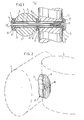
- two round poles 2 of a play implement are connected with one another.
- bores 3 are made in the poles 2.
- a bolt 4 serving as a clamping means of the device 1.
- the head 26 of the bolt 4 bears on a supporting element 5, which is in contact with the left-hand pole 2.
- The. screwthreaded end of the bolt 4 engages a supporting element 6 on the other side of the device.
- the supporting element 6 has a shank 12 with a tapped hole 11 and a head 13.
- On its side facing the shank 12 the head 13 has a flat face.
- the flat face of the head 13 bears on a flat face of a ring 7.
- the ring 7 bears on the pole 2.
- a spacing member 8 is arranged between the poles 2 and the connecting device. This spacing member 8 holds the poles 2 at a minimum distance so that no hazardous, narrow, wedge-shaped gap is formed between the poles.
- the spacing element has curved faces 20, 21 which intimately engage the poles at least along an outer edge.
- the supporting element 5 and the ring 7 associated with the supporting element 6 also have curved contact faces 22 and 23 respectively, which fit to the surface of the poles 2.
- the supporting element 5 and the spacing element 8 are provided with shoulders 9 and 10 respectively. Any shear forces occurring between the poles 2 are transferred by the shoulders 10 of the spacing element 8. In this way the connecting device itself is prevented from being exposed to shear forces.
- the shoulder 9 the supporting element 5 is correctly positioned with respect to the bore 3.
- Fig. 1 furthermore shows that the supporting element 5 has a recess 14 for receiving the head 26 of the clamping element or else the bolt 4.
- the outer edge of the supporting element 5 has a bevelled face 25 so that the risk of injury due to sharp edges of the supporting element 5 itself or the bolt head 26 is eliminated.
- the supporting elements 5 and 6 with the ring 7 are shown in detail in Fig. 3.
- the spacing element 8 is shown in detail in Fig. 7.
- Fig. 2 shows a spacing element embodying the invention in a schematic view at its place between two beams 2.
- a clamping element for example, a bolt 4 as shown in Fig. 1.
- the centre lines of the curvatures of the curved contact faces 16 and 17 are at right angles to one another so that this spacing element is intended to be used in a connecting device interconnecting two poles 2 at an angle of 90°.
- the spacing element in the connecting device embodying the invention has the advantageous, additional effect that the interconnected poles 2 are fixed in the correct angular position and that a relative turn of the poles 2 is prevented by the curved faces.
- Fig. 3 shows in detail the above-described elements of the connecting device embodying the invention shown in Fig. 1.
- the supporting element 5 and the ring 7 are, by their respective, curved contact faces 23 and 22, in engagement with the poles 2.
- the nut element 6 can be turned because the underside 27 of the head 6 is flat and is in contact with the flat face 28 of the ring 7.
- the bolt 4 (not shown in Fig. 3) is passed through the supporting element 5 and the poles and at the other end the nut element 6 passed through the ring 7 is screwed onto the bolt.
- the head 13 of the nut element 6 has a hexagonal recess 29 into which a hexagonal wrench can be inserted.
- Figs. 1 and 3 furthermore show that the ring 7 is provided with lugs 24 which penetrate into the material of the pole 2 and have the effect of guard elements.
- the curved face 22 of the supporting element 5 or the curved faces of the spacing elements may also be provided with lugs.
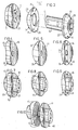
- the spacing element 30 shown in Fig. 5 has curved contact faces 31 and 32 on both sides, the centre lines of.the curvatures extending parallel to one another.
- the spacing element 30 is used for interconnecting poles in parallel position.
- the spacing element as shown in Fig. 6 has on one side a flat face 34 and on the other side a curved contact face 35.
- two partial rings 35 engaging one another by their flat faces 34 poles can be interconnected at any arbitrary angle because the curved faces 35 of the respective partial rings can be relatively turned at any angle.
- the elements 8, 36 and 37 shown in Figs. 7 to 9 respectively basically correspond with the elements 15, 30, 33 of Figs. 4, 5 and 6 respectively.
- the spacing element 8 is described with reference to Fig. 1 and it differs from the spacing element 15 of Figs. 2 and 4 in that it is provided with shoulders 10.
- the spacing elements 36 and 37 are also provided with shoulders.
- the spacing element 40 of Fig. 10 comprises two partial rings 41.
- the partial rings 41 basically correspond with the partial ring 37 of Fig. 9, but arresting members formed by a toothing 42 are provided in the flat face.
- the teeth may be disposed at relative angular distances of 15°.
- the arresting members provide the advantage that the poles are guarded against a turn in the selected angular position.
- sharp members may be used in one or in both flat faces to penetrate into the material of the flat face of the opposite partial ring 41.
- the spacing element 45 of Fig. 11 comprises a pipe 46 provided near the ends with rings 47 welded thereto.
- the rings 47 are chosen so that the curved contact face 50 is formed on the side facing the associated end of the pipe 46.
- the spacing element 45 can be connected at both ends with a pole by means of a bolt bearing on the supporting element, for example, the supporting element 5 of Fig. 3.
- the spacing element 45 serves as the rung of a ladder, as a horizontal bar or as a part of railing.
- F ig. 12 shows a further development of the spacing element shown in Fig. ll.
- This spacing element 51 comprises three bars 56 secured at both ends to locking members 52.
- the locking members 52 are constructed so that their outer rim 54 forms the curved contact face.
- To the locking members 52 are fastened bolts 53 which can be passed through bores in the pole concerned, whilst a nut 55 can be screwed onto the other end.
- the spacing element 51 may be used with the curvature of the bars 56 pointing upwards or downwards.
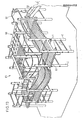
- the play implement 65 comprises a large number of poles 2, which are interconnected in different ways by means of the device embodying the invention.
- foot boards 61 In the play implement 65 are formed foot boards 61 and, in addition, a slide 58 and a suspension bridge 60. There is also provided a slide rod 59.
- Fig. 13 clearly shows the various above-mentioned embodiments of the connecting device in accordance with the invention.
Landscapes
- Engineering & Computer Science (AREA)
- General Engineering & Computer Science (AREA)
- Mechanical Engineering (AREA)
- Mutual Connection Of Rods And Tubes (AREA)
- Road Signs Or Road Markings (AREA)
- Toys (AREA)
- Golf Clubs (AREA)
- Adornments (AREA)
- Clamps And Clips (AREA)
- Joining Of Building Structures In Genera (AREA)
Abstract
Description
- The invention relates to a device for connecting at least two round poles of a play implement comprising clamping means extending through bores in the poles and bearing via supporting elements on the outer faces on both sides of the poles.
- The play implements for which the device embodying, the invention is intended to be used are usually outdoor constructions of round wooden poles, for example, climbing bars and the like. It is known to interconnect the round wooden poles of such play implements by means of a bolt. Washers are put below the bolt head and below the nut to form supporting elements. The poles are directly drawn against one another.
- In practice it has been found that play implements mounted by means of the known connecting devices do not fully satisfy the severe requirements of safety that have to be imposed on these play implements intended to be used by children. In particular, the child's fingers may readily be jammed in the wedge-shaped gap formed by two directly interconnected poles. Moreover, the washers, the bolt head and the nut constitute a potential source of injuries.
- The invention has for its object to provide a device of the kind set forth by means of which a play implement can be built which satisfies severe safety requirements.
- This is achieved in such a connecting device embodying the invention by a spacing element extending between the poles coaxially with the clamping means and having curved contact faces fittingly engaging the poles at least along an outer edge. It is thus ensured that at any point of the construction of the play implement the poles are spaced apart by a minimum distance determined by the spacing element so that the gaps between the poles are not so close to another that fingers are likely to be jammed. Since the spacing element has curved contact faces matching the poles at least along one outer edge no other gaps or sharp edges are formed, which might cause injuries or pinching.
- According to the invention in order to establish a direct connection of the poles the spacing element is formed by a ring having a curved face on both sides. The curved faces may have their centre lines parallel to one another or at an angle to one another. The poles can be connected with one another in accordance with the angele between said centre lines. The spacing element constitutes in addition an advantageous guard against a turn of the poles so that a robust, stable construction is obtained, which is of paramount importance for a play implement.
- If the poles have to be interconnected at an arbitrary angle, the spacing element embodying the invention comprises two partial rings being in contact with one another by flat side faces and each having a curved face on the side opposite the flat face. The partial rings can relatively turn along the flat faces so that any angle can be formed.
- In a further development of the invention relatively co-operating arresting members are provided in each flat side face of the partial rings. In this way it is yet possible to obtain the advantage of guarding the poles against a relative turn. The arresting members may have the shape of sharp tips penetrating into the material of the opposite partial ring or of teeth arranged at fixed angular distances, for example, angles of 15°. In the latter case the spacing element formed by the partial rings permits of establishing an angular connection in which the angle formed is a multiple of 15°.
- For interconnecting poles at a larger distance the spacing element embodying the invention is formed by a pipe or rod provided near each end with a ring having a curved face. Such a spacing element may be advantageously employed as a rung of a ladder or as a horizontal bar. The matching contact faces ensure the desired safety, whilst at the same time a very firm connection is established which prevents the poles from turning relatively to one another.
- In the case of such a long spacing element the pipe or rod preferably has at each end a hole with internal screwthread. Then the clamping elements are two bolts passed each through one pole and engaging the tapped hole of the spacing element.
- In order to avoid injuries due to the supporting elements each supporting element in a further development of the invention has a curved contact face fitting at least along an outer edge to the pole.
- A particularly effective connection is established when the clamping means comprise a bolt engaging in the internally screwthreaded shank of a nut element having a head protruding from the shank, said head engaging by an annular, flat face directed to the shank a ring having a curved contact face on the other side.
- According to the invention, in order to prevent the spacing element and the supporting element from turning they can be provided with lugs protruding from the curved face. When the clamping element is tightened, said lugs penetrate into the material of the pole so that a relative turn is avoided.
- An advantageous embodiment of the invention is characterized by a coaxial shoulder on the side(s) of a curved contact face. This coaxial shoulder penetrates into a matching bore in the pole concerned and thus effectively absorbs longitudinal forces exerted on the element.
- The invention will be described more fully with reference to the accompanying drawings.
-
- Fig. 1 is a longitudinal sectional view of a device embodying the invention.
- Fig. 2 is a schematic, perspective view of a spacing element of the device embodying the invention.
- Fig. 3 is a perspective view of part of the device of Fig. 1.
- Figs. 4 to 6 show three embodiments of a spacing element.
- Figs. 7 to 9 are elevational views corresponding to Figs. 4 to 6 of further embodiments of the spacing element.
- Fig. 10 shows a still further embodiment.
- Fig. 11 shows a spacing element for connecting poles at a larger distance.
- Fig. 12 shows a further embodiment of a spacing element.
- Fig. 13 is a perspective view of a play implement formed by poles connected by devices embodying the invention.
- By means of the device embodying the invention two
round poles 2 of a play implement are connected with one another. For this purpose bores 3 are made in thepoles 2. Through the bores 3 extends a bolt 4 serving as a clamping means of the device 1. Thehead 26 of the bolt 4 bears on a supportingelement 5, which is in contact with the left-hand pole 2. The. screwthreaded end of the bolt 4 engages a supportingelement 6 on the other side of the device. The supportingelement 6 has ashank 12 with a tappedhole 11 and ahead 13. On its side facing theshank 12 thehead 13 has a flat face. The flat face of thehead 13 bears on a flat face of a ring 7. The ring 7 bears on thepole 2. According to the invention a spacing member 8 is arranged between thepoles 2 and the connecting device. This spacing member 8 holds thepoles 2 at a minimum distance so that no hazardous, narrow, wedge-shaped gap is formed between the poles. The spacing element has curvedfaces - According to a further aspect of the invention the supporting
element 5 and the ring 7 associated with the supportingelement 6 also havecurved contact faces poles 2. According to an aspect of the invention the supportingelement 5 and the spacing element 8 are provided withshoulders poles 2 are transferred by theshoulders 10 of the spacing element 8. In this way the connecting device itself is prevented from being exposed to shear forces. By theshoulder 9 the supportingelement 5 is correctly positioned with respect to the bore 3. Fig. 1 furthermore shows that the supportingelement 5 has arecess 14 for receiving thehead 26 of the clamping element or else the bolt 4. The outer edge of the supportingelement 5 has abevelled face 25 so that the risk of injury due to sharp edges of the supportingelement 5 itself or thebolt head 26 is eliminated. The supportingelements - Fig. 2 shows a spacing element embodying the invention in a schematic view at its place between two
beams 2. Through thehole 18 in the middle of thespacing element 15 extends a clamping element, for example, a bolt 4 as shown in Fig. 1. From Fig. 2 it is clearly apparent how the curved contact faces 16 and 17 match the shapes of thepoles 2. In this embodiment of thespacing element 15 the centre lines of the curvatures of the curved contact faces 16 and 17 are at right angles to one another so that this spacing element is intended to be used in a connecting device interconnecting twopoles 2 at an angle of 90°. - As stated above, the spacing element in the connecting device embodying the invention has the advantageous, additional effect that the
interconnected poles 2 are fixed in the correct angular position and that a relative turn of thepoles 2 is prevented by the curved faces. - Fig. 3 shows in detail the above-described elements of the connecting device embodying the invention shown in Fig. 1. The supporting
element 5 and the ring 7 are, by their respective, curved contact faces 23 and 22, in engagement with thepoles 2. Thenut element 6 can be turned because theunderside 27 of thehead 6 is flat and is in contact with theflat face 28 of the ring 7. For mounting the device the bolt 4 (not shown in Fig. 3) is passed through the supportingelement 5 and the poles and at the other end thenut element 6 passed through the ring 7 is screwed onto the bolt. For tightening the connection thehead 13 of thenut element 6 has ahexagonal recess 29 into which a hexagonal wrench can be inserted. - Figs. 1 and 3 furthermore show that the ring 7 is provided with
lugs 24 which penetrate into the material of thepole 2 and have the effect of guard elements. Apart from the curved face of the ring 7, thecurved face 22 of the supportingelement 5 or the curved faces of the spacing elements may also be provided with lugs. - As set out above the centre lines of the curvatures on the two sides of the
spacing element 15, as shown in Fig. 4, are at right angles to one another so that the poles are also connected at an angle of 90° with one another. - The
spacing element 30 shown in Fig. 5 has curved contact faces 31 and 32 on both sides, the centre lines of.the curvatures extending parallel to one another. Thespacing element 30 is used for interconnecting poles in parallel position. - The spacing element as shown in Fig. 6 has on one side a
flat face 34 and on the other side acurved contact face 35. By using as spacing elements twopartial rings 35 engaging one another by their flat faces 34 poles can be interconnected at any arbitrary angle because the curved faces 35 of the respective partial rings can be relatively turned at any angle. - The
elements elements spacing element 15 of Figs. 2 and 4 in that it is provided withshoulders 10. Thespacing elements - The
spacing element 40 of Fig. 10 comprises twopartial rings 41. The partial rings 41 basically correspond with thepartial ring 37 of Fig. 9, but arresting members formed by a toothing 42 are provided in the flat face. The teeth may be disposed at relative angular distances of 15°. In this way the twopartial rings 41 can be employed for a connecting device embodying the invention to connect poles with one another at an angle of an integral multiple of 15°. The arresting members provide the advantage that the poles are guarded against a turn in the selected angular position. Instead of using co-operating teeth, sharp members may be used in one or in both flat faces to penetrate into the material of the flat face of the oppositepartial ring 41. - The
spacing element 45 of Fig. 11 comprises apipe 46 provided near the ends withrings 47 welded thereto. Therings 47 are chosen so that thecurved contact face 50 is formed on the side facing the associated end of thepipe 46. Into the ends of thepipe 46 are introducedscrewthreaded sleeves 48, which are guarded in place by means of adepression 49. Thespacing element 45 can be connected at both ends with a pole by means of a bolt bearing on the supporting element, for example, the supportingelement 5 of Fig. 3. Thespacing element 45, as is shown in Fig. 13, serves as the rung of a ladder, as a horizontal bar or as a part of railing. Although the distance between the poles to be interconnected, when using aspacing element 45, is relatively large, the additional advantage of the invention of guarding the poles against a relative turn is nevertheless obtained. - Fig. 12 shows a further development of the spacing element shown in Fig. ll. This
spacing element 51 comprises threebars 56 secured at both ends to lockingmembers 52. The lockingmembers 52 are constructed so that theirouter rim 54 forms the curved contact face. To the lockingmembers 52 are fastenedbolts 53 which can be passed through bores in the pole concerned, whilst anut 55 can be screwed onto the other end. - As is shown in Fig. 13, the
spacing element 51 may be used with the curvature of thebars 56 pointing upwards or downwards. The play implement 65 comprises a large number ofpoles 2, which are interconnected in different ways by means of the device embodying the invention. In the play implement 65 are formed foot boards 61 and, in addition, aslide 58 and a suspension bridge 60. There is also provided aslide rod 59. It will be obvious that by means of the connecting device embodying the invention a large number of different play appliances can be formed. Fig. 13 clearly shows the various above-mentioned embodiments of the connecting device in accordance with the invention. When the device embodying the invention is employed, children, even when playing boisterously, will not get jammed or injured, whilst by the additional advantage of the invention in guarding the interconnected poles against a relative turn a very rigid and robust construction is obtained.
Claims (10)
Priority Applications (1)
| Application Number | Priority Date | Filing Date | Title |
|---|---|---|---|
| AT83200076T ATE30515T1 (en) | 1982-01-20 | 1983-01-18 | CONNECTING DEVICE FOR ROUND RODS OF PLAY EQUIPMENT. |
Applications Claiming Priority (2)
| Application Number | Priority Date | Filing Date | Title |
|---|---|---|---|
| NL8200204 | 1982-01-20 | ||
| NL8200204A NL8200204A (en) | 1982-01-20 | 1982-01-20 | CONNECTING DEVICE FOR ROUND POSTS OF A TOOL. |
Publications (3)
| Publication Number | Publication Date |
|---|---|
| EP0085452A2 true EP0085452A2 (en) | 1983-08-10 |
| EP0085452A3 EP0085452A3 (en) | 1983-08-17 |
| EP0085452B1 EP0085452B1 (en) | 1987-11-04 |
Family
ID=19839110
Family Applications (1)
| Application Number | Title | Priority Date | Filing Date |
|---|---|---|---|
| EP83200076A Expired EP0085452B1 (en) | 1982-01-20 | 1983-01-18 | Connecting device for round poles of a play implement |
Country Status (5)
| Country | Link |
|---|---|
| EP (1) | EP0085452B1 (en) |
| AT (1) | ATE30515T1 (en) |
| DE (1) | DE3374275D1 (en) |
| DK (1) | DK158067C (en) |
| NL (1) | NL8200204A (en) |
Cited By (6)
| Publication number | Priority date | Publication date | Assignee | Title |
|---|---|---|---|---|
| GB2173569A (en) * | 1985-04-01 | 1986-10-15 | Univ London | Slide module for prosthetic alignment device |
| EP0384439A1 (en) * | 1989-02-22 | 1990-08-29 | Uwe Tisch | Wall system, in particular a climbing wall, and exchangeable wall element |
| FR2662951A1 (en) * | 1990-06-11 | 1991-12-13 | Husson Collectivites Sa | MODULAR GAME DEVICE. |
| DE9206646U1 (en) * | 1992-05-15 | 1992-10-22 | Pax Schweikhard GmbH, 6507 Ingelheim | Screw connection of plastic hollow profiles |
| EP2832260A3 (en) * | 2013-08-02 | 2015-02-18 | Muebles Romero, S.A. | Connecting device |
| WO2015140284A1 (en) * | 2014-03-21 | 2015-09-24 | Kompan A/S | A playground |
Family Cites Families (6)
| Publication number | Priority date | Publication date | Assignee | Title |
|---|---|---|---|---|
| FR612018A (en) * | 1926-03-02 | 1926-10-15 | Tube assembly mode | |
| FR1079838A (en) * | 1953-02-24 | 1954-12-02 | Million Guiet Tubauto | Device for fixing tubular elements of seats and similar applications |
| GB897382A (en) * | 1957-12-13 | 1962-05-23 | Siddall & Hilton Ltd | Improvements in or relating to washers and methods of bolting using such washers |
| US3046040A (en) * | 1960-05-31 | 1962-07-24 | Forrest E Luper | Joint structure for tubing |
| US3814416A (en) * | 1971-05-25 | 1974-06-04 | Northwest Design Prod Inc | Playground climbing structures |
| US4252313A (en) * | 1979-04-18 | 1981-02-24 | Victor Stanley, Inc. | Playground equipment |
-
1982
- 1982-01-20 NL NL8200204A patent/NL8200204A/en not_active Application Discontinuation
-
1983
- 1983-01-18 DE DE8383200076T patent/DE3374275D1/en not_active Expired
- 1983-01-18 AT AT83200076T patent/ATE30515T1/en not_active IP Right Cessation
- 1983-01-18 DK DK018083A patent/DK158067C/en not_active IP Right Cessation
- 1983-01-18 EP EP83200076A patent/EP0085452B1/en not_active Expired
Cited By (11)
| Publication number | Priority date | Publication date | Assignee | Title |
|---|---|---|---|---|
| GB2173569A (en) * | 1985-04-01 | 1986-10-15 | Univ London | Slide module for prosthetic alignment device |
| EP0384439A1 (en) * | 1989-02-22 | 1990-08-29 | Uwe Tisch | Wall system, in particular a climbing wall, and exchangeable wall element |
| FR2662951A1 (en) * | 1990-06-11 | 1991-12-13 | Husson Collectivites Sa | MODULAR GAME DEVICE. |
| EP0462039A1 (en) * | 1990-06-11 | 1991-12-18 | Husson Collectivites, S.A. | Modular toy device |
| DE9206646U1 (en) * | 1992-05-15 | 1992-10-22 | Pax Schweikhard GmbH, 6507 Ingelheim | Screw connection of plastic hollow profiles |
| EP2832260A3 (en) * | 2013-08-02 | 2015-02-18 | Muebles Romero, S.A. | Connecting device |
| WO2015140284A1 (en) * | 2014-03-21 | 2015-09-24 | Kompan A/S | A playground |
| US10525298B2 (en) | 2014-03-21 | 2020-01-07 | Kompan A/S | Playground |
| EP3739138A1 (en) | 2014-03-21 | 2020-11-18 | Kompan A/S | A playground |
| US11471720B2 (en) | 2014-03-21 | 2022-10-18 | Kompan A/S | Playground |
| EP4461898A1 (en) | 2014-03-21 | 2024-11-13 | Kompan A/S | A playground |
Also Published As
| Publication number | Publication date |
|---|---|
| NL8200204A (en) | 1983-08-16 |
| ATE30515T1 (en) | 1987-11-15 |
| EP0085452B1 (en) | 1987-11-04 |
| DK158067C (en) | 1990-08-20 |
| DK18083A (en) | 1983-07-21 |
| DK158067B (en) | 1990-03-26 |
| DE3374275D1 (en) | 1987-12-10 |
| EP0085452A3 (en) | 1983-08-17 |
| DK18083D0 (en) | 1983-01-18 |
Similar Documents
| Publication | Publication Date | Title |
|---|---|---|
| KR880000984B1 (en) | A locking or securing device | |
| US3969871A (en) | Fastening construction for playground equipment | |
| US5112155A (en) | Connector for assembling components of scaffolding | |
| WO1997007012A9 (en) | Lightweight high strength bicycle seat post and associated clamp | |
| US5497850A (en) | Apparatus for leveling a ladder | |
| US5232067A (en) | Stile extending attachment for ladder | |
| EP0085452B1 (en) | Connecting device for round poles of a play implement | |
| CA2178334A1 (en) | Device at power line poles | |
| US4641727A (en) | Electrically insulated temporary aerial platform | |
| US5701971A (en) | Protective member for metal scaffold knots or joints | |
| EP0666614B1 (en) | Bimetallic connector | |
| US3355195A (en) | Joint structure for plate members | |
| PL330918A1 (en) | Jointing fastener for scaffolding ledgers | |
| GB2109079A (en) | Improvements in fastener devices primarily for recreational or gymnastic frames | |
| US11471720B2 (en) | Playground | |
| DE4134945C2 (en) | Impact bottom sleeve | |
| TW369582B (en) | Movement limiting device for bridge bearing | |
| AU2007101088B4 (en) | A Clamp | |
| KR20000012670A (en) | A device of preventing dismantlement of bolts and nuts | |
| KR102798694B1 (en) | Fall preventing structure | |
| JPH057440Y2 (en) | ||
| AU733546B2 (en) | Gable end safety rail bracket support | |
| GB1591371A (en) | Device for use in clamping two elongated components in transverse relationship | |
| KR870000390Y1 (en) | Joint for ceiling board | |
| KR0124503Y1 (en) | Assembling clamper of a pipe structure |
Legal Events
| Date | Code | Title | Description |
|---|---|---|---|
| PUAI | Public reference made under article 153(3) epc to a published international application that has entered the european phase |
Free format text: ORIGINAL CODE: 0009012 |
|
| PUAL | Search report despatched |
Free format text: ORIGINAL CODE: 0009013 |
|
| AK | Designated contracting states |
Designated state(s): AT BE CH DE FR GB IT LI LU NL SE |
|
| AK | Designated contracting states |
Designated state(s): AT BE CH DE FR GB IT LI LU NL SE |
|
| 17P | Request for examination filed |
Effective date: 19840208 |
|
| GRAA | (expected) grant |
Free format text: ORIGINAL CODE: 0009210 |
|
| AK | Designated contracting states |
Kind code of ref document: B1 Designated state(s): AT BE CH DE FR GB IT LI LU NL SE |
|
| PG25 | Lapsed in a contracting state [announced via postgrant information from national office to epo] |
Ref country code: IT Free format text: LAPSE BECAUSE OF FAILURE TO SUBMIT A TRANSLATION OF THE DESCRIPTION OR TO PAY THE FEE WITHIN THE PRESCRIBED TIME-LIMIT;WARNING: LAPSES OF ITALIAN PATENTS WITH EFFECTIVE DATE BEFORE 2007 MAY HAVE OCCURRED AT ANY TIME BEFORE 2007. THE CORRECT EFFECTIVE DATE MAY BE DIFFERENT FROM THE ONE RECORDED. Effective date: 19871104 |
|
| REF | Corresponds to: |
Ref document number: 30515 Country of ref document: AT Date of ref document: 19871115 Kind code of ref document: T |
|
| PG25 | Lapsed in a contracting state [announced via postgrant information from national office to epo] |
Ref country code: SE Effective date: 19871130 |
|
| REF | Corresponds to: |
Ref document number: 3374275 Country of ref document: DE Date of ref document: 19871210 |
|
| ET | Fr: translation filed | ||
| PG25 | Lapsed in a contracting state [announced via postgrant information from national office to epo] |
Ref country code: LU Free format text: LAPSE BECAUSE OF NON-PAYMENT OF DUE FEES Effective date: 19880131 |
|
| PLBE | No opposition filed within time limit |
Free format text: ORIGINAL CODE: 0009261 |
|
| STAA | Information on the status of an ep patent application or granted ep patent |
Free format text: STATUS: NO OPPOSITION FILED WITHIN TIME LIMIT |
|
| 26N | No opposition filed | ||
| PGFP | Annual fee paid to national office [announced via postgrant information from national office to epo] |
Ref country code: CH Payment date: 19990128 Year of fee payment: 17 |
|
| PGFP | Annual fee paid to national office [announced via postgrant information from national office to epo] |
Ref country code: DE Payment date: 19990202 Year of fee payment: 17 |
|
| PGFP | Annual fee paid to national office [announced via postgrant information from national office to epo] |
Ref country code: NL Payment date: 19990630 Year of fee payment: 17 |
|
| PGFP | Annual fee paid to national office [announced via postgrant information from national office to epo] |
Ref country code: FR Payment date: 19991210 Year of fee payment: 18 |
|
| PGFP | Annual fee paid to national office [announced via postgrant information from national office to epo] |
Ref country code: BE Payment date: 19991228 Year of fee payment: 18 |
|
| PGFP | Annual fee paid to national office [announced via postgrant information from national office to epo] |
Ref country code: AT Payment date: 20000111 Year of fee payment: 18 |
|
| PGFP | Annual fee paid to national office [announced via postgrant information from national office to epo] |
Ref country code: GB Payment date: 20000112 Year of fee payment: 18 |
|
| PG25 | Lapsed in a contracting state [announced via postgrant information from national office to epo] |
Ref country code: DE Free format text: LAPSE BECAUSE OF THE APPLICANT RENOUNCES Effective date: 20000126 |
|
| PG25 | Lapsed in a contracting state [announced via postgrant information from national office to epo] |
Ref country code: LI Free format text: LAPSE BECAUSE OF NON-PAYMENT OF DUE FEES Effective date: 20000131 Ref country code: CH Free format text: LAPSE BECAUSE OF NON-PAYMENT OF DUE FEES Effective date: 20000131 |
|
| PG25 | Lapsed in a contracting state [announced via postgrant information from national office to epo] |
Ref country code: NL Free format text: LAPSE BECAUSE OF NON-PAYMENT OF DUE FEES Effective date: 20000801 |
|
| REG | Reference to a national code |
Ref country code: CH Ref legal event code: PL |
|
| NLV4 | Nl: lapsed or anulled due to non-payment of the annual fee |
Effective date: 20000801 |
|
| PG25 | Lapsed in a contracting state [announced via postgrant information from national office to epo] |
Ref country code: GB Free format text: LAPSE BECAUSE OF NON-PAYMENT OF DUE FEES Effective date: 20010118 Ref country code: AT Free format text: LAPSE BECAUSE OF NON-PAYMENT OF DUE FEES Effective date: 20010118 |
|
| PG25 | Lapsed in a contracting state [announced via postgrant information from national office to epo] |
Ref country code: BE Free format text: LAPSE BECAUSE OF NON-PAYMENT OF DUE FEES Effective date: 20010131 |
|
| BERE | Be: lapsed |
Owner name: SPEELHOUT B.V. Effective date: 20010131 |
|
| GBPC | Gb: european patent ceased through non-payment of renewal fee |
Effective date: 20010118 |
|
| PG25 | Lapsed in a contracting state [announced via postgrant information from national office to epo] |
Ref country code: FR Free format text: LAPSE BECAUSE OF NON-PAYMENT OF DUE FEES Effective date: 20010928 |
|
| REG | Reference to a national code |
Ref country code: FR Ref legal event code: ST |