EP0085410A2 - Process for joining the metallic inner and outer parts of a composite profile member - Google Patents
Process for joining the metallic inner and outer parts of a composite profile member Download PDFInfo
- Publication number
- EP0085410A2 EP0085410A2 EP83100783A EP83100783A EP0085410A2 EP 0085410 A2 EP0085410 A2 EP 0085410A2 EP 83100783 A EP83100783 A EP 83100783A EP 83100783 A EP83100783 A EP 83100783A EP 0085410 A2 EP0085410 A2 EP 0085410A2
- Authority
- EP
- European Patent Office
- Prior art keywords
- additional material
- insulating web
- jacket
- outer parts
- composite profile
- Prior art date
- Legal status (The legal status is an assumption and is not a legal conclusion. Google has not performed a legal analysis and makes no representation as to the accuracy of the status listed.)
- Granted
Links
Images

Classifications
-
- E—FIXED CONSTRUCTIONS
- E06—DOORS, WINDOWS, SHUTTERS, OR ROLLER BLINDS IN GENERAL; LADDERS
- E06B—FIXED OR MOVABLE CLOSURES FOR OPENINGS IN BUILDINGS, VEHICLES, FENCES OR LIKE ENCLOSURES IN GENERAL, e.g. DOORS, WINDOWS, BLINDS, GATES
- E06B3/00—Window sashes, door leaves, or like elements for closing wall or like openings; Layout of fixed or moving closures, e.g. windows in wall or like openings; Features of rigidly-mounted outer frames relating to the mounting of wing frames
- E06B3/04—Wing frames not characterised by the manner of movement
- E06B3/263—Frames with special provision for insulation
- E06B3/277—Frames with special provision for insulation with prefabricated insulating elements held in position by expansion of the extremities of the insulating elements
-
- B—PERFORMING OPERATIONS; TRANSPORTING
- B29—WORKING OF PLASTICS; WORKING OF SUBSTANCES IN A PLASTIC STATE IN GENERAL
- B29C—SHAPING OR JOINING OF PLASTICS; SHAPING OF MATERIAL IN A PLASTIC STATE, NOT OTHERWISE PROVIDED FOR; AFTER-TREATMENT OF THE SHAPED PRODUCTS, e.g. REPAIRING
- B29C44/00—Shaping by internal pressure generated in the material, e.g. swelling or foaming ; Producing porous or cellular expanded plastics articles
- B29C44/02—Shaping by internal pressure generated in the material, e.g. swelling or foaming ; Producing porous or cellular expanded plastics articles for articles of definite length, i.e. discrete articles
- B29C44/12—Incorporating or moulding on preformed parts, e.g. inserts or reinforcements
- B29C44/1228—Joining preformed parts by the expanding material
-
- B—PERFORMING OPERATIONS; TRANSPORTING
- B29—WORKING OF PLASTICS; WORKING OF SUBSTANCES IN A PLASTIC STATE IN GENERAL
- B29C—SHAPING OR JOINING OF PLASTICS; SHAPING OF MATERIAL IN A PLASTIC STATE, NOT OTHERWISE PROVIDED FOR; AFTER-TREATMENT OF THE SHAPED PRODUCTS, e.g. REPAIRING
- B29C44/00—Shaping by internal pressure generated in the material, e.g. swelling or foaming ; Producing porous or cellular expanded plastics articles
- B29C44/34—Auxiliary operations
- B29C44/3484—Stopping the foaming reaction until the material is heated or re-heated
-
- B—PERFORMING OPERATIONS; TRANSPORTING
- B29—WORKING OF PLASTICS; WORKING OF SUBSTANCES IN A PLASTIC STATE IN GENERAL
- B29C—SHAPING OR JOINING OF PLASTICS; SHAPING OF MATERIAL IN A PLASTIC STATE, NOT OTHERWISE PROVIDED FOR; AFTER-TREATMENT OF THE SHAPED PRODUCTS, e.g. REPAIRING
- B29C65/00—Joining or sealing of preformed parts, e.g. welding of plastics materials; Apparatus therefor
- B29C65/02—Joining or sealing of preformed parts, e.g. welding of plastics materials; Apparatus therefor by heating, with or without pressure
- B29C65/34—Joining or sealing of preformed parts, e.g. welding of plastics materials; Apparatus therefor by heating, with or without pressure using heated elements which remain in the joint, e.g. "verlorenes Schweisselement"
- B29C65/3404—Joining or sealing of preformed parts, e.g. welding of plastics materials; Apparatus therefor by heating, with or without pressure using heated elements which remain in the joint, e.g. "verlorenes Schweisselement" characterised by the type of heated elements which remain in the joint
- B29C65/342—Joining or sealing of preformed parts, e.g. welding of plastics materials; Apparatus therefor by heating, with or without pressure using heated elements which remain in the joint, e.g. "verlorenes Schweisselement" characterised by the type of heated elements which remain in the joint comprising at least a single wire, e.g. in the form of a winding
-
- B—PERFORMING OPERATIONS; TRANSPORTING
- B29—WORKING OF PLASTICS; WORKING OF SUBSTANCES IN A PLASTIC STATE IN GENERAL
- B29C—SHAPING OR JOINING OF PLASTICS; SHAPING OF MATERIAL IN A PLASTIC STATE, NOT OTHERWISE PROVIDED FOR; AFTER-TREATMENT OF THE SHAPED PRODUCTS, e.g. REPAIRING
- B29C65/00—Joining or sealing of preformed parts, e.g. welding of plastics materials; Apparatus therefor
- B29C65/02—Joining or sealing of preformed parts, e.g. welding of plastics materials; Apparatus therefor by heating, with or without pressure
- B29C65/34—Joining or sealing of preformed parts, e.g. welding of plastics materials; Apparatus therefor by heating, with or without pressure using heated elements which remain in the joint, e.g. "verlorenes Schweisselement"
- B29C65/3472—Joining or sealing of preformed parts, e.g. welding of plastics materials; Apparatus therefor by heating, with or without pressure using heated elements which remain in the joint, e.g. "verlorenes Schweisselement" characterised by the composition of the heated elements which remain in the joint
- B29C65/3476—Joining or sealing of preformed parts, e.g. welding of plastics materials; Apparatus therefor by heating, with or without pressure using heated elements which remain in the joint, e.g. "verlorenes Schweisselement" characterised by the composition of the heated elements which remain in the joint being metallic
-
- B—PERFORMING OPERATIONS; TRANSPORTING
- B29—WORKING OF PLASTICS; WORKING OF SUBSTANCES IN A PLASTIC STATE IN GENERAL
- B29C—SHAPING OR JOINING OF PLASTICS; SHAPING OF MATERIAL IN A PLASTIC STATE, NOT OTHERWISE PROVIDED FOR; AFTER-TREATMENT OF THE SHAPED PRODUCTS, e.g. REPAIRING
- B29C65/00—Joining or sealing of preformed parts, e.g. welding of plastics materials; Apparatus therefor
- B29C65/48—Joining or sealing of preformed parts, e.g. welding of plastics materials; Apparatus therefor using adhesives, i.e. using supplementary joining material; solvent bonding
- B29C65/4805—Joining or sealing of preformed parts, e.g. welding of plastics materials; Apparatus therefor using adhesives, i.e. using supplementary joining material; solvent bonding characterised by the type of adhesives
- B29C65/481—Non-reactive adhesives, e.g. physically hardening adhesives
- B29C65/4815—Hot melt adhesives, e.g. thermoplastic adhesives
-
- B—PERFORMING OPERATIONS; TRANSPORTING
- B29—WORKING OF PLASTICS; WORKING OF SUBSTANCES IN A PLASTIC STATE IN GENERAL
- B29C—SHAPING OR JOINING OF PLASTICS; SHAPING OF MATERIAL IN A PLASTIC STATE, NOT OTHERWISE PROVIDED FOR; AFTER-TREATMENT OF THE SHAPED PRODUCTS, e.g. REPAIRING
- B29C65/00—Joining or sealing of preformed parts, e.g. welding of plastics materials; Apparatus therefor
- B29C65/48—Joining or sealing of preformed parts, e.g. welding of plastics materials; Apparatus therefor using adhesives, i.e. using supplementary joining material; solvent bonding
- B29C65/4805—Joining or sealing of preformed parts, e.g. welding of plastics materials; Apparatus therefor using adhesives, i.e. using supplementary joining material; solvent bonding characterised by the type of adhesives
- B29C65/483—Reactive adhesives, e.g. chemically curing adhesives
- B29C65/4835—Heat curing adhesives
-
- B—PERFORMING OPERATIONS; TRANSPORTING
- B29—WORKING OF PLASTICS; WORKING OF SUBSTANCES IN A PLASTIC STATE IN GENERAL
- B29C—SHAPING OR JOINING OF PLASTICS; SHAPING OF MATERIAL IN A PLASTIC STATE, NOT OTHERWISE PROVIDED FOR; AFTER-TREATMENT OF THE SHAPED PRODUCTS, e.g. REPAIRING
- B29C65/00—Joining or sealing of preformed parts, e.g. welding of plastics materials; Apparatus therefor
- B29C65/48—Joining or sealing of preformed parts, e.g. welding of plastics materials; Apparatus therefor using adhesives, i.e. using supplementary joining material; solvent bonding
- B29C65/4855—Joining or sealing of preformed parts, e.g. welding of plastics materials; Apparatus therefor using adhesives, i.e. using supplementary joining material; solvent bonding characterised by their physical properties, e.g. being electrically-conductive
-
- B—PERFORMING OPERATIONS; TRANSPORTING
- B29—WORKING OF PLASTICS; WORKING OF SUBSTANCES IN A PLASTIC STATE IN GENERAL
- B29C—SHAPING OR JOINING OF PLASTICS; SHAPING OF MATERIAL IN A PLASTIC STATE, NOT OTHERWISE PROVIDED FOR; AFTER-TREATMENT OF THE SHAPED PRODUCTS, e.g. REPAIRING
- B29C65/00—Joining or sealing of preformed parts, e.g. welding of plastics materials; Apparatus therefor
- B29C65/48—Joining or sealing of preformed parts, e.g. welding of plastics materials; Apparatus therefor using adhesives, i.e. using supplementary joining material; solvent bonding
- B29C65/4865—Joining or sealing of preformed parts, e.g. welding of plastics materials; Apparatus therefor using adhesives, i.e. using supplementary joining material; solvent bonding containing additives
- B29C65/487—Joining or sealing of preformed parts, e.g. welding of plastics materials; Apparatus therefor using adhesives, i.e. using supplementary joining material; solvent bonding containing additives characterised by their shape, e.g. being fibres or being spherical
- B29C65/4875—Joining or sealing of preformed parts, e.g. welding of plastics materials; Apparatus therefor using adhesives, i.e. using supplementary joining material; solvent bonding containing additives characterised by their shape, e.g. being fibres or being spherical being spherical, e.g. particles or powders
-
- B—PERFORMING OPERATIONS; TRANSPORTING
- B29—WORKING OF PLASTICS; WORKING OF SUBSTANCES IN A PLASTIC STATE IN GENERAL
- B29C—SHAPING OR JOINING OF PLASTICS; SHAPING OF MATERIAL IN A PLASTIC STATE, NOT OTHERWISE PROVIDED FOR; AFTER-TREATMENT OF THE SHAPED PRODUCTS, e.g. REPAIRING
- B29C65/00—Joining or sealing of preformed parts, e.g. welding of plastics materials; Apparatus therefor
- B29C65/48—Joining or sealing of preformed parts, e.g. welding of plastics materials; Apparatus therefor using adhesives, i.e. using supplementary joining material; solvent bonding
- B29C65/50—Joining or sealing of preformed parts, e.g. welding of plastics materials; Apparatus therefor using adhesives, i.e. using supplementary joining material; solvent bonding using adhesive tape, e.g. thermoplastic tape; using threads or the like
- B29C65/5007—Joining or sealing of preformed parts, e.g. welding of plastics materials; Apparatus therefor using adhesives, i.e. using supplementary joining material; solvent bonding using adhesive tape, e.g. thermoplastic tape; using threads or the like characterised by the structure of said adhesive tape, threads or the like
- B29C65/5021—Joining or sealing of preformed parts, e.g. welding of plastics materials; Apparatus therefor using adhesives, i.e. using supplementary joining material; solvent bonding using adhesive tape, e.g. thermoplastic tape; using threads or the like characterised by the structure of said adhesive tape, threads or the like being multi-layered
-
- B—PERFORMING OPERATIONS; TRANSPORTING
- B29—WORKING OF PLASTICS; WORKING OF SUBSTANCES IN A PLASTIC STATE IN GENERAL
- B29C—SHAPING OR JOINING OF PLASTICS; SHAPING OF MATERIAL IN A PLASTIC STATE, NOT OTHERWISE PROVIDED FOR; AFTER-TREATMENT OF THE SHAPED PRODUCTS, e.g. REPAIRING
- B29C65/00—Joining or sealing of preformed parts, e.g. welding of plastics materials; Apparatus therefor
- B29C65/48—Joining or sealing of preformed parts, e.g. welding of plastics materials; Apparatus therefor using adhesives, i.e. using supplementary joining material; solvent bonding
- B29C65/50—Joining or sealing of preformed parts, e.g. welding of plastics materials; Apparatus therefor using adhesives, i.e. using supplementary joining material; solvent bonding using adhesive tape, e.g. thermoplastic tape; using threads or the like
- B29C65/5007—Joining or sealing of preformed parts, e.g. welding of plastics materials; Apparatus therefor using adhesives, i.e. using supplementary joining material; solvent bonding using adhesive tape, e.g. thermoplastic tape; using threads or the like characterised by the structure of said adhesive tape, threads or the like
- B29C65/5035—Joining or sealing of preformed parts, e.g. welding of plastics materials; Apparatus therefor using adhesives, i.e. using supplementary joining material; solvent bonding using adhesive tape, e.g. thermoplastic tape; using threads or the like characterised by the structure of said adhesive tape, threads or the like being in thread form, i.e. in the form of a single filament, e.g. in the form of a single coated filament
-
- B—PERFORMING OPERATIONS; TRANSPORTING
- B29—WORKING OF PLASTICS; WORKING OF SUBSTANCES IN A PLASTIC STATE IN GENERAL
- B29C—SHAPING OR JOINING OF PLASTICS; SHAPING OF MATERIAL IN A PLASTIC STATE, NOT OTHERWISE PROVIDED FOR; AFTER-TREATMENT OF THE SHAPED PRODUCTS, e.g. REPAIRING
- B29C65/00—Joining or sealing of preformed parts, e.g. welding of plastics materials; Apparatus therefor
- B29C65/48—Joining or sealing of preformed parts, e.g. welding of plastics materials; Apparatus therefor using adhesives, i.e. using supplementary joining material; solvent bonding
- B29C65/50—Joining or sealing of preformed parts, e.g. welding of plastics materials; Apparatus therefor using adhesives, i.e. using supplementary joining material; solvent bonding using adhesive tape, e.g. thermoplastic tape; using threads or the like
- B29C65/5057—Joining or sealing of preformed parts, e.g. welding of plastics materials; Apparatus therefor using adhesives, i.e. using supplementary joining material; solvent bonding using adhesive tape, e.g. thermoplastic tape; using threads or the like positioned between the surfaces to be joined
-
- B—PERFORMING OPERATIONS; TRANSPORTING
- B29—WORKING OF PLASTICS; WORKING OF SUBSTANCES IN A PLASTIC STATE IN GENERAL
- B29C—SHAPING OR JOINING OF PLASTICS; SHAPING OF MATERIAL IN A PLASTIC STATE, NOT OTHERWISE PROVIDED FOR; AFTER-TREATMENT OF THE SHAPED PRODUCTS, e.g. REPAIRING
- B29C65/00—Joining or sealing of preformed parts, e.g. welding of plastics materials; Apparatus therefor
- B29C65/48—Joining or sealing of preformed parts, e.g. welding of plastics materials; Apparatus therefor using adhesives, i.e. using supplementary joining material; solvent bonding
- B29C65/52—Joining or sealing of preformed parts, e.g. welding of plastics materials; Apparatus therefor using adhesives, i.e. using supplementary joining material; solvent bonding characterised by the way of applying the adhesive
- B29C65/54—Joining or sealing of preformed parts, e.g. welding of plastics materials; Apparatus therefor using adhesives, i.e. using supplementary joining material; solvent bonding characterised by the way of applying the adhesive between pre-assembled parts
- B29C65/542—Joining or sealing of preformed parts, e.g. welding of plastics materials; Apparatus therefor using adhesives, i.e. using supplementary joining material; solvent bonding characterised by the way of applying the adhesive between pre-assembled parts by injection
-
- B—PERFORMING OPERATIONS; TRANSPORTING
- B29—WORKING OF PLASTICS; WORKING OF SUBSTANCES IN A PLASTIC STATE IN GENERAL
- B29C—SHAPING OR JOINING OF PLASTICS; SHAPING OF MATERIAL IN A PLASTIC STATE, NOT OTHERWISE PROVIDED FOR; AFTER-TREATMENT OF THE SHAPED PRODUCTS, e.g. REPAIRING
- B29C66/00—General aspects of processes or apparatus for joining preformed parts
- B29C66/01—General aspects dealing with the joint area or with the area to be joined
- B29C66/05—Particular design of joint configurations
- B29C66/10—Particular design of joint configurations particular design of the joint cross-sections
- B29C66/12—Joint cross-sections combining only two joint-segments; Tongue and groove joints; Tenon and mortise joints; Stepped joint cross-sections
- B29C66/124—Tongue and groove joints
- B29C66/1242—Tongue and groove joints comprising interlocking undercuts
- B29C66/12423—Dovetailed interlocking undercuts
-
- B—PERFORMING OPERATIONS; TRANSPORTING
- B29—WORKING OF PLASTICS; WORKING OF SUBSTANCES IN A PLASTIC STATE IN GENERAL
- B29C—SHAPING OR JOINING OF PLASTICS; SHAPING OF MATERIAL IN A PLASTIC STATE, NOT OTHERWISE PROVIDED FOR; AFTER-TREATMENT OF THE SHAPED PRODUCTS, e.g. REPAIRING
- B29C66/00—General aspects of processes or apparatus for joining preformed parts
- B29C66/01—General aspects dealing with the joint area or with the area to be joined
- B29C66/05—Particular design of joint configurations
- B29C66/10—Particular design of joint configurations particular design of the joint cross-sections
- B29C66/12—Joint cross-sections combining only two joint-segments; Tongue and groove joints; Tenon and mortise joints; Stepped joint cross-sections
- B29C66/124—Tongue and groove joints
- B29C66/1244—Tongue and groove joints characterised by the male part, i.e. the part comprising the tongue
- B29C66/12441—Tongue and groove joints characterised by the male part, i.e. the part comprising the tongue being a single wall
-
- B—PERFORMING OPERATIONS; TRANSPORTING
- B29—WORKING OF PLASTICS; WORKING OF SUBSTANCES IN A PLASTIC STATE IN GENERAL
- B29C—SHAPING OR JOINING OF PLASTICS; SHAPING OF MATERIAL IN A PLASTIC STATE, NOT OTHERWISE PROVIDED FOR; AFTER-TREATMENT OF THE SHAPED PRODUCTS, e.g. REPAIRING
- B29C66/00—General aspects of processes or apparatus for joining preformed parts
- B29C66/01—General aspects dealing with the joint area or with the area to be joined
- B29C66/05—Particular design of joint configurations
- B29C66/303—Particular design of joint configurations the joint involving an anchoring effect
-
- B—PERFORMING OPERATIONS; TRANSPORTING
- B29—WORKING OF PLASTICS; WORKING OF SUBSTANCES IN A PLASTIC STATE IN GENERAL
- B29C—SHAPING OR JOINING OF PLASTICS; SHAPING OF MATERIAL IN A PLASTIC STATE, NOT OTHERWISE PROVIDED FOR; AFTER-TREATMENT OF THE SHAPED PRODUCTS, e.g. REPAIRING
- B29C66/00—General aspects of processes or apparatus for joining preformed parts
- B29C66/40—General aspects of joining substantially flat articles, e.g. plates, sheets or web-like materials; Making flat seams in tubular or hollow articles; Joining single elements to substantially flat surfaces
- B29C66/41—Joining substantially flat articles ; Making flat seams in tubular or hollow articles
- B29C66/43—Joining a relatively small portion of the surface of said articles
- B29C66/434—Joining substantially flat articles for forming corner connections, fork connections or cross connections
- B29C66/4344—Joining substantially flat articles for forming fork connections, e.g. for making Y-shaped pieces
- B29C66/43441—Joining substantially flat articles for forming fork connections, e.g. for making Y-shaped pieces with two right angles, e.g. for making T-shaped pieces, H-shaped pieces
-
- B—PERFORMING OPERATIONS; TRANSPORTING
- B29—WORKING OF PLASTICS; WORKING OF SUBSTANCES IN A PLASTIC STATE IN GENERAL
- B29C—SHAPING OR JOINING OF PLASTICS; SHAPING OF MATERIAL IN A PLASTIC STATE, NOT OTHERWISE PROVIDED FOR; AFTER-TREATMENT OF THE SHAPED PRODUCTS, e.g. REPAIRING
- B29C66/00—General aspects of processes or apparatus for joining preformed parts
- B29C66/50—General aspects of joining tubular articles; General aspects of joining long products, i.e. bars or profiled elements; General aspects of joining single elements to tubular articles, hollow articles or bars; General aspects of joining several hollow-preforms to form hollow or tubular articles
- B29C66/51—Joining tubular articles, profiled elements or bars; Joining single elements to tubular articles, hollow articles or bars; Joining several hollow-preforms to form hollow or tubular articles
- B29C66/52—Joining tubular articles, bars or profiled elements
- B29C66/524—Joining profiled elements
-
- B—PERFORMING OPERATIONS; TRANSPORTING
- B29—WORKING OF PLASTICS; WORKING OF SUBSTANCES IN A PLASTIC STATE IN GENERAL
- B29C—SHAPING OR JOINING OF PLASTICS; SHAPING OF MATERIAL IN A PLASTIC STATE, NOT OTHERWISE PROVIDED FOR; AFTER-TREATMENT OF THE SHAPED PRODUCTS, e.g. REPAIRING
- B29C66/00—General aspects of processes or apparatus for joining preformed parts
- B29C66/70—General aspects of processes or apparatus for joining preformed parts characterised by the composition, physical properties or the structure of the material of the parts to be joined; Joining with non-plastics material
- B29C66/74—Joining plastics material to non-plastics material
- B29C66/742—Joining plastics material to non-plastics material to metals or their alloys
-
- B—PERFORMING OPERATIONS; TRANSPORTING
- B29—WORKING OF PLASTICS; WORKING OF SUBSTANCES IN A PLASTIC STATE IN GENERAL
- B29C—SHAPING OR JOINING OF PLASTICS; SHAPING OF MATERIAL IN A PLASTIC STATE, NOT OTHERWISE PROVIDED FOR; AFTER-TREATMENT OF THE SHAPED PRODUCTS, e.g. REPAIRING
- B29C65/00—Joining or sealing of preformed parts, e.g. welding of plastics materials; Apparatus therefor
- B29C65/02—Joining or sealing of preformed parts, e.g. welding of plastics materials; Apparatus therefor by heating, with or without pressure
- B29C65/34—Joining or sealing of preformed parts, e.g. welding of plastics materials; Apparatus therefor by heating, with or without pressure using heated elements which remain in the joint, e.g. "verlorenes Schweisselement"
- B29C65/36—Joining or sealing of preformed parts, e.g. welding of plastics materials; Apparatus therefor by heating, with or without pressure using heated elements which remain in the joint, e.g. "verlorenes Schweisselement" heated by induction
- B29C65/3604—Joining or sealing of preformed parts, e.g. welding of plastics materials; Apparatus therefor by heating, with or without pressure using heated elements which remain in the joint, e.g. "verlorenes Schweisselement" heated by induction characterised by the type of elements heated by induction which remain in the joint
- B29C65/362—Joining or sealing of preformed parts, e.g. welding of plastics materials; Apparatus therefor by heating, with or without pressure using heated elements which remain in the joint, e.g. "verlorenes Schweisselement" heated by induction characterised by the type of elements heated by induction which remain in the joint comprising at least a single wire, e.g. in the form of a winding
-
- B—PERFORMING OPERATIONS; TRANSPORTING
- B29—WORKING OF PLASTICS; WORKING OF SUBSTANCES IN A PLASTIC STATE IN GENERAL
- B29C—SHAPING OR JOINING OF PLASTICS; SHAPING OF MATERIAL IN A PLASTIC STATE, NOT OTHERWISE PROVIDED FOR; AFTER-TREATMENT OF THE SHAPED PRODUCTS, e.g. REPAIRING
- B29C65/00—Joining or sealing of preformed parts, e.g. welding of plastics materials; Apparatus therefor
- B29C65/02—Joining or sealing of preformed parts, e.g. welding of plastics materials; Apparatus therefor by heating, with or without pressure
- B29C65/34—Joining or sealing of preformed parts, e.g. welding of plastics materials; Apparatus therefor by heating, with or without pressure using heated elements which remain in the joint, e.g. "verlorenes Schweisselement"
- B29C65/36—Joining or sealing of preformed parts, e.g. welding of plastics materials; Apparatus therefor by heating, with or without pressure using heated elements which remain in the joint, e.g. "verlorenes Schweisselement" heated by induction
- B29C65/3604—Joining or sealing of preformed parts, e.g. welding of plastics materials; Apparatus therefor by heating, with or without pressure using heated elements which remain in the joint, e.g. "verlorenes Schweisselement" heated by induction characterised by the type of elements heated by induction which remain in the joint
- B29C65/3644—Joining or sealing of preformed parts, e.g. welding of plastics materials; Apparatus therefor by heating, with or without pressure using heated elements which remain in the joint, e.g. "verlorenes Schweisselement" heated by induction characterised by the type of elements heated by induction which remain in the joint being a ribbon, band or strip
-
- B—PERFORMING OPERATIONS; TRANSPORTING
- B29—WORKING OF PLASTICS; WORKING OF SUBSTANCES IN A PLASTIC STATE IN GENERAL
- B29C—SHAPING OR JOINING OF PLASTICS; SHAPING OF MATERIAL IN A PLASTIC STATE, NOT OTHERWISE PROVIDED FOR; AFTER-TREATMENT OF THE SHAPED PRODUCTS, e.g. REPAIRING
- B29C65/00—Joining or sealing of preformed parts, e.g. welding of plastics materials; Apparatus therefor
- B29C65/02—Joining or sealing of preformed parts, e.g. welding of plastics materials; Apparatus therefor by heating, with or without pressure
- B29C65/34—Joining or sealing of preformed parts, e.g. welding of plastics materials; Apparatus therefor by heating, with or without pressure using heated elements which remain in the joint, e.g. "verlorenes Schweisselement"
- B29C65/36—Joining or sealing of preformed parts, e.g. welding of plastics materials; Apparatus therefor by heating, with or without pressure using heated elements which remain in the joint, e.g. "verlorenes Schweisselement" heated by induction
- B29C65/3672—Joining or sealing of preformed parts, e.g. welding of plastics materials; Apparatus therefor by heating, with or without pressure using heated elements which remain in the joint, e.g. "verlorenes Schweisselement" heated by induction characterised by the composition of the elements heated by induction which remain in the joint
- B29C65/3676—Joining or sealing of preformed parts, e.g. welding of plastics materials; Apparatus therefor by heating, with or without pressure using heated elements which remain in the joint, e.g. "verlorenes Schweisselement" heated by induction characterised by the composition of the elements heated by induction which remain in the joint being metallic
- B29C65/368—Joining or sealing of preformed parts, e.g. welding of plastics materials; Apparatus therefor by heating, with or without pressure using heated elements which remain in the joint, e.g. "verlorenes Schweisselement" heated by induction characterised by the composition of the elements heated by induction which remain in the joint being metallic with a polymer coating
-
- B—PERFORMING OPERATIONS; TRANSPORTING
- B29—WORKING OF PLASTICS; WORKING OF SUBSTANCES IN A PLASTIC STATE IN GENERAL
- B29C—SHAPING OR JOINING OF PLASTICS; SHAPING OF MATERIAL IN A PLASTIC STATE, NOT OTHERWISE PROVIDED FOR; AFTER-TREATMENT OF THE SHAPED PRODUCTS, e.g. REPAIRING
- B29C66/00—General aspects of processes or apparatus for joining preformed parts
- B29C66/01—General aspects dealing with the joint area or with the area to be joined
- B29C66/05—Particular design of joint configurations
- B29C66/303—Particular design of joint configurations the joint involving an anchoring effect
- B29C66/3032—Particular design of joint configurations the joint involving an anchoring effect making use of protusions or cavities belonging to at least one of the parts to be joined
- B29C66/30321—Particular design of joint configurations the joint involving an anchoring effect making use of protusions or cavities belonging to at least one of the parts to be joined making use of protusions belonging to at least one of the parts to be joined
-
- B—PERFORMING OPERATIONS; TRANSPORTING
- B29—WORKING OF PLASTICS; WORKING OF SUBSTANCES IN A PLASTIC STATE IN GENERAL
- B29C—SHAPING OR JOINING OF PLASTICS; SHAPING OF MATERIAL IN A PLASTIC STATE, NOT OTHERWISE PROVIDED FOR; AFTER-TREATMENT OF THE SHAPED PRODUCTS, e.g. REPAIRING
- B29C66/00—General aspects of processes or apparatus for joining preformed parts
- B29C66/70—General aspects of processes or apparatus for joining preformed parts characterised by the composition, physical properties or the structure of the material of the parts to be joined; Joining with non-plastics material
- B29C66/71—General aspects of processes or apparatus for joining preformed parts characterised by the composition, physical properties or the structure of the material of the parts to be joined; Joining with non-plastics material characterised by the composition of the plastics material of the parts to be joined
-
- B—PERFORMING OPERATIONS; TRANSPORTING
- B29—WORKING OF PLASTICS; WORKING OF SUBSTANCES IN A PLASTIC STATE IN GENERAL
- B29C—SHAPING OR JOINING OF PLASTICS; SHAPING OF MATERIAL IN A PLASTIC STATE, NOT OTHERWISE PROVIDED FOR; AFTER-TREATMENT OF THE SHAPED PRODUCTS, e.g. REPAIRING
- B29C66/00—General aspects of processes or apparatus for joining preformed parts
- B29C66/70—General aspects of processes or apparatus for joining preformed parts characterised by the composition, physical properties or the structure of the material of the parts to be joined; Joining with non-plastics material
- B29C66/72—General aspects of processes or apparatus for joining preformed parts characterised by the composition, physical properties or the structure of the material of the parts to be joined; Joining with non-plastics material characterised by the structure of the material of the parts to be joined
- B29C66/721—Fibre-reinforced materials
- B29C66/7212—Fibre-reinforced materials characterised by the composition of the fibres
-
- B—PERFORMING OPERATIONS; TRANSPORTING
- B29—WORKING OF PLASTICS; WORKING OF SUBSTANCES IN A PLASTIC STATE IN GENERAL
- B29C—SHAPING OR JOINING OF PLASTICS; SHAPING OF MATERIAL IN A PLASTIC STATE, NOT OTHERWISE PROVIDED FOR; AFTER-TREATMENT OF THE SHAPED PRODUCTS, e.g. REPAIRING
- B29C66/00—General aspects of processes or apparatus for joining preformed parts
- B29C66/70—General aspects of processes or apparatus for joining preformed parts characterised by the composition, physical properties or the structure of the material of the parts to be joined; Joining with non-plastics material
- B29C66/73—General aspects of processes or apparatus for joining preformed parts characterised by the composition, physical properties or the structure of the material of the parts to be joined; Joining with non-plastics material characterised by the intensive physical properties of the material of the parts to be joined, by the optical properties of the material of the parts to be joined, by the extensive physical properties of the parts to be joined, by the state of the material of the parts to be joined or by the material of the parts to be joined being a thermoplastic or a thermoset
- B29C66/731—General aspects of processes or apparatus for joining preformed parts characterised by the composition, physical properties or the structure of the material of the parts to be joined; Joining with non-plastics material characterised by the intensive physical properties of the material of the parts to be joined, by the optical properties of the material of the parts to be joined, by the extensive physical properties of the parts to be joined, by the state of the material of the parts to be joined or by the material of the parts to be joined being a thermoplastic or a thermoset characterised by the intensive physical properties of the material of the parts to be joined
- B29C66/7316—Surface properties
- B29C66/73161—Roughness or rugosity
- B29C66/73162—Roughness or rugosity of different roughness or rugosity, i.e. the roughness or rugosity of the surface of one of the parts to be joined being different from the roughness or rugosity of the surface of the other part
-
- B—PERFORMING OPERATIONS; TRANSPORTING
- B29—WORKING OF PLASTICS; WORKING OF SUBSTANCES IN A PLASTIC STATE IN GENERAL
- B29C—SHAPING OR JOINING OF PLASTICS; SHAPING OF MATERIAL IN A PLASTIC STATE, NOT OTHERWISE PROVIDED FOR; AFTER-TREATMENT OF THE SHAPED PRODUCTS, e.g. REPAIRING
- B29C66/00—General aspects of processes or apparatus for joining preformed parts
- B29C66/70—General aspects of processes or apparatus for joining preformed parts characterised by the composition, physical properties or the structure of the material of the parts to be joined; Joining with non-plastics material
- B29C66/73—General aspects of processes or apparatus for joining preformed parts characterised by the composition, physical properties or the structure of the material of the parts to be joined; Joining with non-plastics material characterised by the intensive physical properties of the material of the parts to be joined, by the optical properties of the material of the parts to be joined, by the extensive physical properties of the parts to be joined, by the state of the material of the parts to be joined or by the material of the parts to be joined being a thermoplastic or a thermoset
- B29C66/739—General aspects of processes or apparatus for joining preformed parts characterised by the composition, physical properties or the structure of the material of the parts to be joined; Joining with non-plastics material characterised by the intensive physical properties of the material of the parts to be joined, by the optical properties of the material of the parts to be joined, by the extensive physical properties of the parts to be joined, by the state of the material of the parts to be joined or by the material of the parts to be joined being a thermoplastic or a thermoset characterised by the material of the parts to be joined being a thermoplastic or a thermoset
- B29C66/7392—General aspects of processes or apparatus for joining preformed parts characterised by the composition, physical properties or the structure of the material of the parts to be joined; Joining with non-plastics material characterised by the intensive physical properties of the material of the parts to be joined, by the optical properties of the material of the parts to be joined, by the extensive physical properties of the parts to be joined, by the state of the material of the parts to be joined or by the material of the parts to be joined being a thermoplastic or a thermoset characterised by the material of the parts to be joined being a thermoplastic or a thermoset characterised by the material of at least one of the parts being a thermoplastic
-
- E—FIXED CONSTRUCTIONS
- E06—DOORS, WINDOWS, SHUTTERS, OR ROLLER BLINDS IN GENERAL; LADDERS
- E06B—FIXED OR MOVABLE CLOSURES FOR OPENINGS IN BUILDINGS, VEHICLES, FENCES OR LIKE ENCLOSURES IN GENERAL, e.g. DOORS, WINDOWS, BLINDS, GATES
- E06B3/00—Window sashes, door leaves, or like elements for closing wall or like openings; Layout of fixed or moving closures, e.g. windows in wall or like openings; Features of rigidly-mounted outer frames relating to the mounting of wing frames
- E06B3/04—Wing frames not characterised by the manner of movement
- E06B3/263—Frames with special provision for insulation
- E06B3/26301—Frames with special provision for insulation with prefabricated insulating strips between two metal section members
- E06B3/26305—Connection details
- E06B2003/26309—Connection details using glue
-
- E—FIXED CONSTRUCTIONS
- E06—DOORS, WINDOWS, SHUTTERS, OR ROLLER BLINDS IN GENERAL; LADDERS
- E06B—FIXED OR MOVABLE CLOSURES FOR OPENINGS IN BUILDINGS, VEHICLES, FENCES OR LIKE ENCLOSURES IN GENERAL, e.g. DOORS, WINDOWS, BLINDS, GATES
- E06B3/00—Window sashes, door leaves, or like elements for closing wall or like openings; Layout of fixed or moving closures, e.g. windows in wall or like openings; Features of rigidly-mounted outer frames relating to the mounting of wing frames
- E06B3/04—Wing frames not characterised by the manner of movement
- E06B3/263—Frames with special provision for insulation
- E06B3/26301—Frames with special provision for insulation with prefabricated insulating strips between two metal section members
- E06B3/26305—Connection details
- E06B2003/26314—Provisions for reducing the shift between the strips and the metal section members
-
- E—FIXED CONSTRUCTIONS
- E06—DOORS, WINDOWS, SHUTTERS, OR ROLLER BLINDS IN GENERAL; LADDERS
- E06B—FIXED OR MOVABLE CLOSURES FOR OPENINGS IN BUILDINGS, VEHICLES, FENCES OR LIKE ENCLOSURES IN GENERAL, e.g. DOORS, WINDOWS, BLINDS, GATES
- E06B3/00—Window sashes, door leaves, or like elements for closing wall or like openings; Layout of fixed or moving closures, e.g. windows in wall or like openings; Features of rigidly-mounted outer frames relating to the mounting of wing frames
- E06B3/04—Wing frames not characterised by the manner of movement
- E06B3/263—Frames with special provision for insulation
- E06B3/273—Frames with special provision for insulation with prefabricated insulating elements held in position by deformation of portions of the metal frame members
Definitions
- the invention relates to a method for connecting the metallic inner and outer parts of a composite profile with an insulating web which engages with its ends in grooves of the inner and outer parts.
- the positive connection is improved in that the insulating web has depressions into which the grooves delimiting webs during their deformation can penetrate.
- the object is achieved in that an additional material in the form of at least one wire, tape, strip or film is introduced into the grooves of the inner and outer parts in the region of the ends of the insulating web and it is pressure and / or heat in its own material modified in such a way, in particular deformed, that there is an improved form, force and / or material connection between the insulating web and the inner and outer parts of the composite profile.
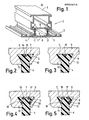
- Fig. 1 shows a z. B. for the production of windows, doors, facade elements or the like.
- Suitable metal composite profile 1 with an inner part 2 and an outer part 3, both of which are connected to one another by two longitudinal insulating webs 4, 5.
- the parts 2, 3 can for example consist of Aluminum, aluminum alloy or steel exist.
- the insulating webs 4, 5, which produce a heat-insulating bridge between the parts 2, 3, consist of high-strength plastic with poor thermal conduction properties, for example of glass fiber reinforced polyamide.
- the insulating webs 4, 5 protrude with their dovetail-shaped ends 6 into correspondingly designed, longitudinal grooves 7 of the composite profile parts 2, 3, cf. Fig. 2.
- a longitudinally continuous chamber 11 is formed in the finished composite profile between the insulating webs 4, 5 and wall sections 8, 9 of the parts 2 and 3, a longitudinally continuous chamber 11 is formed.
- the ends of the insulating webs 4, 5 are first inserted lengthwise into the grooves 7, for example drawn in. Subsequently, a drawing mandrel is pulled through the chamber 11 in the longitudinal direction of the profile, as a result of which the webs lying in this chamber and delimiting the groove 7 (denoted by 12 in FIG. 2) are pressed onto the ends 6 of the insulating webs 4, 5, so that the Insulating webs 4, 5 are finally held in a form-fitting manner between the aforementioned web 12 and an opposite grooved web (in FIG . 2_ with 13).
- FIGS. 2 to 9 and 11 to 16 each show sections in the area of the circle denoted by A in FIG. 1.
- Various embodiments of methods according to the invention are then based on this section using the mentioned figures explained. These statements also relate in the same way to the circular areas designated B, C and D in FIG. 1, where the same measures are taken in each case.
- an additional material in the form of a wire 15 is inserted and by appropriate deformation of the groove web 12 together with the end 6 in the web formed by this web and the opposite groove web 13 Groove included.
- the additional material forming the wire 15 is selected according to the invention such that its material properties can be modified, in particular deformed, by pressure and / or heat in such a way that an improved positive and / or non-positive connection between the insulating web 4 and the inner and outer parts 2 or 3 of the composite profile 1 results.
- the additional material is preferably a plastic, but can also be a low-melting metal. It is particularly advantageous to use a longitudinally stretched wire 15 made of plastic which expands in the transverse direction when heated. Suitable plastic materials are, for example, stretched (longitudinally oriented) polyamide copolymers, but also hot-melt adhesives which expand permanently by heating, in particular copolymers prepared on the basis of acrylic acid and acrylic acid esters. 3 shows the state after heating and expansion of the wire 15 in the transverse direction. Due to the transverse forces generated during this expansion, the positive and non-positive connection of the end 6 in the lateral groove 7 delimited by the webs 12, 13 is considerably increased, so that the longitudinal shear strength between the insulating web 4 and the associated composite profile part 3 is improved. The load-bearing capacity of a window, door or facade element produced in this way is thus increased, so that increased safety requirements can now also be taken into account.
- FIGS. 4 and 5 show a modified embodiment of the method explained with reference to FIGS. 2 and 3, wherein instead of a single plastic wire 15 several such wires 16, 17, 18, 19 are used, which are distributed over all of the groove walls delimiting the groove 7 .
- FIG. 5 again shows the state after transverse expansion of the wires 16, 17, 18 and 19.
- the strength-improving additional material can also be introduced in the form of a tape, a strip, a material application, a film or a compound intruded into a space between the insulating web and the inner walls of the grooves.
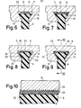
- FIGS. 6 and 7 show, in the manner already explained, the use of an additional material in the form of a strip or strip 21.
- the introduction takes place in a space between the top of the insulating web 4 and the groove base 22.
- expansion is again carried out by applying pressure or heat so that the distribution shown in FIG. 7 results.
- a mass with corresponding material properties can also be intruded into this space. This does not change the desired result, namely an improvement in the shear strength between the insulating web 4 and the groove 7 encompassing it.
- the strength of the connection described can be further improved according to the invention if one introduces an additional material together with the web 4 into the groove 7, which brings about an adhesive connection between the end 6 of the insulating web and the groove 7 when heat and / or pressure is applied, and admittedly with the advantage that an additional material that melts when heated is used.
- Suitable materials for this are, for example, thermoplastic hot melt adhesives, e.g. B. a copolymer based on acrylic acid or acrylic acid ester, alone or in combination with a pressure sensitive adhesive, for. B. based on phenolic resin-nitryl rubber. Otherwise, the procedure is as explained with reference to FIGS. 2 to 7, although this is not absolutely necessary is that the additional material mediating an adhesive connection expands in the transverse direction even with appropriate heat or pressure treatment, even if this is fundamentally advantageous.
- FIGS. 8 and 9 in turn show - before or after heat or pressure treatment - the use of an additional material which improves the strength of the connection on three sides of the groove.
- the additional material is introduced here (FIG. 8) together with the web 4 in the form of strip-like foils 23 into the groove 7.
- FIG. 8 the mutually facing surfaces of the insulating web end 6 and the groove 7 are roughened by knurling 24 and 25 on the surface.
- the frictional engagement and thus the overall shear strength is further improved because the additional material of the foils 23 can penetrate into the knurls and solidify there.
- the surface roughness described with reference to FIGS. 8, 9 and 10, for example in the form of knurling, can also be used in the embodiments of the method according to the invention according to FIGS. 2 to 7 and 11 to 16.
- a further modified method according to the invention is that a material that can be hardened by heat and / or pressure is introduced as an additional material into the groove, for example again in the form of a wire, strip or tape as shown in FIG. 2 or 6. Since this material according to appropriate treatment becomes harder than the material of the insulating web 4, the overall strength is improved in the area of the force or material connection present in the groove 6. Superficial roughening of FIG. 1 0 may be helpful here again.
- the pressure required for the modification, in particular the deformation, of a pressure-sensitive additional material is preferably obtained from the pressure required to apply the grooved web 12 (through the aforementioned drawing mandrel) to the end 6 of the insulating web 4. This is a process that is carried out in any case, so that one can save the application of special pressures in a separate process step.
- thermosensitive additional material it is particularly advantageous if the heat required for modification, in particular shaping, of a thermosensitive additional material is obtained from a process step which has to be carried out in any case during the production of the composite profile shown in FIG. 1.
- a process step is, for example, a post-treatment of the parts 2, 3 and the insulating webs 4, 5 existing composite profile in the form of anodizing or stove enamelling. , Found out about the additional material in the desired manner to enable thermally to expand in particular or to melt - the necessary in these processes temperatures range, it was ge.
- a pressure required for modifying the additional material can also be applied additionally and in a special process step.
- heating the additional material can be carried out, for example, by ultrasound or high-frequency treatment.
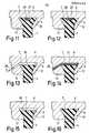
- FIGS. 11 and 12 show a particularly preferred method in which, together with a thermosensitive additional material in the form of a wire 26, a metallic heating wire 27 is additionally introduced into the groove receiving the insulating web 4.
- the heating wire 27 is then connected to an electrical voltage source.
- the heat generated causes the material of the wire 26 to melt and expand, so that it, including the heating wire 27, exerts pressure on the material of the insulating web end 6 and clamps this end more firmly in the associated groove 7.
- the metal heating wire 27 is a hard material, which opposes a harmful resilience more resistance than the softer Material of the insulating web 4 and the wire 26. An improvement in strength can also be achieved in this respect.
- the additional material is introduced into a space 29 through a channel in the groove web 13 in the direction of arrow P and modified in the manner described by heat or pressure in such a way that there is an improved shear strength between Insulating bridge and inner or outer part of the composite profile 1 results.
- the passage 29 g of the in Fi. 1 illustrates g e-faced chamber 11 leads out into the space 29th
- the additional material in question is first introduced into the chamber 11 and from there passes under appropriate pressure through channels 28 provided at appropriate intervals into the intermediate space 29. Also in the embodiment according to FIG.
- FIG. 14 shows the end result of the last-mentioned embodiment of the method according to the invention, after additional material 31 that solidifies in the intermediate space 29 has been introduced.
- a final embodiment of the method according to the invention consists in using part of the material of the insulating web 4 in the groove 7 itself as additional material and pressing this part into the recesses of the groove walls which increase the shape and / or non-positive fit by means of ultrasound treatment these recesses turn knurling 25 of FIG. 1 may be 0. (This knurling is not specifically shown in FIGS. 13 and 14.) With lower demands on the shear strength, such knurling can also be omitted.
- ultrasound generators are preferably attached to the groove web 13 where the insulating web 4 emerges from the groove 7.
- the last-described method based on the use of ultrasound is particularly suitable for insulating webs 4 which are made of polyamide.
- Thermosets, casting resins, for example polyurethane resins, are particularly suitable as curable additional materials, as mentioned above.
- Polyamide materials are particularly suitable for heating by ultrasound.
- Thermosetting materials can be heated by high-frequency treatment.
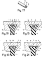
- an additional material in the form of a flexible cord or a flexible wire 15 is inserted into a longitudinal recess 14 at the dovetail-shaped end 6 of the insulating web 4 and by corresponding deformation of the groove web 12 together with the end 6 in the same Web and the opposite groove web 13 formed groove included.
- the diameter of the wire 15 is preferably selected so that it can be easily inserted, in particular inserted, into the groove 14 and remains in place.
- the wire 15 consists of a continuous, central, "soul" forming body 31, which is surrounded by a jacket 32 all around.
- the material forming the body 31 is selected so that it expands (radially) by pressure and / or heat in the transverse direction and thereby presses the end 6 of the insulating web 4 into the groove 7 with the formation of an improved positive fit.
- the material forming the jacket 32 is an adhesive which begins to flow when pressure and / or heat is applied and which pours into the spaces between the end 6 of the insulating web 4 and the groove 7 when the material of the body 31 expands.
- a large-area adhesive connection between the end 6 of the insulating web 4 and the inside of the groove 7 is conveyed, as is shown schematically in FIG. 19. Overall, this measure increases the shear strength of the two parts 2, 3 forming the composite profile 1 by forming a reinforced adhesive and positive connection.
- the body 31 is preferably a monofilament made of plastic, in particular of stretched or unstretched uniform or copolyamide or ethylene copolymer or ionomeric plastic.
- Suitable materials for the jacket 32 are hot-melt adhesives in the form of copolymers based on acrylic acid and acrylic acid esters or ethylene copolymers, and ionomeric hot-melt adhesives; thermosets can also be used for the jacket 32.
- the materials used for the formation of the body 31 and / or the jacket 32 can also contain a blowing agent which expands when pressure and / or heat is applied, which increases the transverse expansion of the body 31 or the large-area distribution of the jacket material favor the groove 7.
- blowing agents that can be used are: azodicaronamides and / or sodium bicarbonate.
- FIGS. 2o and 21 The method according to the invention illustrated with reference to FIGS. 2o and 21 proceeds in exactly the same way as that based on 18 and 19 explained methods.
- the body 31 is surrounded by the jacket 32 all around
- the jacket 32 initially covers the body 31 only on its upper side, the body 31 and jacket 32 being in the form of a flexible band or strip to have.
- pressure and / or heat is applied, the body 31 expands while the jacket 32 melts and penetrates into the spaces between the end 6 of the web 4 and the groove 7.
- 2o shows the initial state
- FIG. 21 the final state.
- the bottom of the groove 7 additionally has a transverse knurling 33 into which the expanding material of the body 31 and the molten material of the jacket 32 can penetrate.
- Knurling 33 could also be provided on the inside of the webs 12, 13 facing the end 6 of the insulating web 4.
- a corresponding roughening or knurling could also have the inside of the groove 7 in the embodiment according to FIGS. 18 and 19.
- the materials of the body 31 and the casing 32 could again be provided with a blowing agent of the type described above.
- the embodiment of a cord or a wire 15 shown in FIG. 22 again consists of an inner body 31 and a sheath 32 surrounding it.
- Hard, sharp-edged particles 34 in particular metal particles, metal chips, quartz grains or the like, are embedded in the sheath 32, which increase the frictional engagement with the inside of the groove 7 when the body 31 expands and when the casing 32 melts, as a result of which the shear strength between the insulating web 4, 5 and the composite profile parts 2, 3 is further increased.
- two metal wires 35 for example made of steel, with a triangular profile and a roughened, in particular corrugated surface, are inserted into the adhesive jacket 32 and partly also into the expandable body 31, the grooved surface protruding somewhat from the peripheral surface of the jacket 32.
- the wires 35 are preferably roughened on their three sides, in particular transversely grooved. When the body 31 expands and the sheath 32 melts, the wires 35 are displaced radially outward and come into positive engagement with the ends of the groove 7 or the top of the insulating web 4. If, in particular, knurling or other surface roughness on the inside of the groove 7 is provided, there is a particularly good positive engagement. As can be seen from FIG. 23, the wires 35 extend axially parallel in the body 31 and sheath 32.
- a wire 15 again consisting of body 31 and sheath 32 is inserted in total into end 6 of insulating web 4 and enclosed on all sides by it.
- Radially extending channels 36 extend in the end 6 of the insulating web 4 and extend from the outer circumference of the wire 15 to the outer sides of the end 6.
- FIG. 25 corresponds in its mode of operation to the methods explained with reference to FIGS. 2 to 24.
- the flexible wire 15 consisting of body 31 and sheath 32 is not inserted into a groove in the end 6 of the web 4, but in a groove 37 of the composite profile part 3.
- the end 6 of the insulating web 4 is pressed firmly into the groove 7 to produce an improved form fit, while on the other hand the adhesive of the jacket 32 is evenly between the end 6 and the insides of the Groove 7 distributed.
Abstract
Description
Die Erfindung betrifft ein Verfahren zum Verbinden der metallischen Innen- und Außenteile eines Verbundprofils mit einem Isoliersteg, der mit seinen Enden in Nuten der Innen- und Außenteile eingreift.The invention relates to a method for connecting the metallic inner and outer parts of a composite profile with an insulating web which engages with its ends in grooves of the inner and outer parts.
Bei einem bekannten Verfahren dieser Art (DE-PS 25 52 7oo) wird zur Erhöhung der Schubfestigkeit zwischen dem Isoliersteg und den Innen- und Außenteilen des Verbundprofils der Formschluß dadurch verbessert, daß der Isoliersteg Vertiefungen aufweist, in welche die Nuten begrenzende Stege bei deren Verformung eindringen können.In a known method of this type (DE-PS 25 52 7oo) to increase the shear strength between the insulating web and the inner and outer parts of the composite profile, the positive connection is improved in that the insulating web has depressions into which the grooves delimiting webs during their deformation can penetrate.
Es ist Aufgabe der Erfindung, weitere Verfahren anzugeben, mit deren Hilfe die Schubfestigkeit zwischen den Teilen des Verbundprofils einerseits und dem Isoliersteg andererseits verbessert werden kann.It is the object of the invention to specify further methods by means of which the shear strength between the parts of the composite profile on the one hand and the insulating web on the other hand can be improved.
Die Aufgabe wird erfindungsgemäß dadurch gelöst, daß man im Bereich der Enden des Isolierstegs ein Zusatzmaterial in Form mindestens eines Drahtes, Bandes, Streifens oder einer Folie mit in die Nuten der Innen- und Außenteile einbringt und es durch Druck und/oder Wärme in seinen Materialeigenschaften derart modifiziert, insbesondere verformt, daß sich ein verbesserter Form-, Kraft- und/oder Stoffschluß zwischen Isoliersteg und den Innen- und Außenteilen des Verbundprofils ergibt.The object is achieved in that an additional material in the form of at least one wire, tape, strip or film is introduced into the grooves of the inner and outer parts in the region of the ends of the insulating web and it is pressure and / or heat in its own material modified in such a way, in particular deformed, that there is an improved form, force and / or material connection between the insulating web and the inner and outer parts of the composite profile.
Die nachstehende Beschreibung bevorzugter Ausführungsformen der Erfindung dient im Zusammenhang mit beiliegender Zeichnung der weiteren Erläuterung. Es zeigen:
- Fig. 1 eine schaubildliche Schnittansicht eines Verbundprofils für Fenster, Türen. Fassadenelemente od. dgl.;
- Fig. 2 Teilansichten des Bereiches A in bis 16 Fig. 1 verschiedener Ausführungsformen von Verfahren zur Verbesserung der Festigkeit zwischen den Verbundprofilteilen mit einem Isoliersteg und
- Fig. 17 weitere Ausführungsformen erfindungsbis 25 gemäßer Verfahren.
- Fig. 1 is a diagrammatic sectional view of a composite profile for windows, doors. Facade elements or the like;
- Fig. 2 partial views of area A in to 16 Fig. 1 different embodiments of methods for improving the strength between the composite profile parts with an insulating web and
- Fig. 17 further embodiments according to the invention according to 25 methods.
Die Fig. 1 zeigt ein z. B. für die Herstellung von Fenstern, Türen, Fass.adenelementen od. dgl. geeignetes Metall-Verbundprofil 1 mit einem Innenteil 2 und einem Außenteil 3, die beide durch zwei längs verlaufende Isolierstege 4, 5 miteinander verbunden sind. Die Teile 2, 3 können beispielsweise aus Aluminium, Aluminiumlegierung oder Stahl bestehen. Die Isolierstege 4, 5, welche eine wärmedämmende Brücke zwischen den Teilen 2, 3 herstellen, bestehen aus hochfestem Kunststoff mit schlechten Wärmeleitungseigenschaften, beispielsweise aus glasfaserverstärktem Polyamid.Fig. 1 shows a z. B. for the production of windows, doors, facade elements or the like. Suitable
Die Isolierstege 4, 5 ragen mit ihren im Querschnitt schwalbenschwanzförmig ausgebildeten Enden 6 in entsprechend ausgebildete, längs verlaufende Nuten 7 der Verbundprofilteile 2, 3 hinein, vgl. Fig. 2. Dabei bildet sich im fertigen Verbundprofil zwischen den Isolierstegen 4, 5 und Wandabschnitten 8, 9 der Teile 2 bzw. 3 eine längsweise durchgehende Kammer 11 aus. Die Isolierstege 4, 5 werden zunächst mit ihren Enden längsweise in die Nuten 7 eingesetzt, beispielsweise eingezogen. Anschließend wird in Längsrichtung des Profils ein Ziehdorn durch die Kammer 11 hindurchgezogen, wodurch die in dieser Kammer liegenden, die Nut 7 begrenzenden Stege (in Fig. 2 mit 12 bezeichnet) an die Enden 6 der Isolierstege 4, 5 angedrückt werden, so daß die Isolierstege 4, 5 schließlich zwischen dem erwähnten Steg 12 und einem gegenüberliegenden Nutensteg (in Fig. 2_mit 13 bezeichnet) formschlüssig gehalten sind.The
Die Figuren 2 bis 9 und 11 bis 16 zeigen jeweils Ausschnitte im Bereich des in Fig. 1 mit A bezeichneten Kreises. Verschiedene Ausführungsformen erfindungsgemäßer Verfahren werden anschließend unter Zugrundelegung dieses Ausschnitts anhand der erwähnten Figuren erläutert. Diese Ausführungen beziehen sich in gleicher Weise auch auf die in Fig. 1 mit B, C und D bezeichneten Kreisbereiche, an denen jeweils gleiche Maßnahmen getroffen werden.FIGS. 2 to 9 and 11 to 16 each show sections in the area of the circle denoted by A in FIG. 1. Various embodiments of methods according to the invention are then based on this section using the mentioned figures explained. These statements also relate in the same way to the circular areas designated B, C and D in FIG. 1, where the same measures are taken in each case.
Bei der Ausführungsform des erfindungsgemäßen Verfahrens gemäß Fig. 2 bis 3 wird zunächst - vgl. Fig. 2 - in eine entsprechende, längs verlaufende Ausnehmung 14 am schwalbenschwanzförmigen Ende 6 des Isoliersteges 4 ein Zusatzmaterial in Gestalt eines Drahtes 15 eingelegt und durch entsprechende Verformung des Nutensteges 12 gemeinsam mit dem Ende 6 in der von diesem Steg und dem gegenüberliegenden Nutensteg 13 gebildeten Nut eingeschlossen. Das den Draht 15 bildende Zusatzmaterial ist erfindungsgemäß so gewählt, daß es durch Druck und/oder Wärme in seinen Materialeigenschaften derart modifiziert, insbesondere verformt werden kann, daß sich ein verbesserter Form- und/oder Kraftschluß zwischen Isoliersteg 4 und den Innen- und Außenteilen 2 bzw. 3 des Verbundprofils 1 ergibt. Das Zusatzmaterial ist vorzugsweise ein Kunststoff, kann aber auch ein niedrig schmelzendes Metall sein. Besonders vorteilhaft ist es, einen längsgereckten Draht 15 aus Kunststoff zu verwenden, der bei Erwärmung in Querrichtung expandiert. Als geeignete Kunststoffmaterialien kommen beispielsweise gereckte (längsorientierte) Polyamid-Copolymerisate in Frage, aber auch durch Erwärmung bleibend expandierende Schmelzkleber, insbesondere auf Acrylsäure- und Acrylsäureester-Basis hergestellte Copolymerisate. Die Fig. 3 zeigt den Zustand nach Erwärmung und Expansion des Drahtes 15 in Querrichtung. Durch die bei dieser Expansion entstehenden Querkräfte wird der Form-und Kraftschluß des Endes 6 in der seitliche von den Stegen 12, 13 begrenzten Nut 7 beträchtlich erhöht, so daß die Schubfestigkeit in Längsrichtung zwischen dem Isoliersteg 4 und dem zugehörigen Verbundprofilteil 3 verbessert ist. Die Tragfähigkeit eines derart hergestellten Fenster-, Tür-oder Fassadenelementes ist somit erhöht, so daß nunmehr auch gesteigerten Sicherheitsanforderungen Rechnung getragen werden kann.In the embodiment of the method according to the invention according to FIGS. 2 to 3, first - cf. Fig. 2 - in a corresponding,
Die Figuren 4 und 5 zeigen eine abgewandelte Ausführungsform des anhand von Fig. 2 und 3 erläuterten Verfahrens, wobei statt eines einzigen Kunststoffdrahtes 15 mehrere solcher Drähte 16, 17, 18, 19 Anwendung finden, die auf sämtliche, die Nut 7 begrenzenden Nutenwände verteilt sind. Die Fig. 5 zeigt wiederum den Zustand nach Querexpansion der Drähte 16, 17, 18 und 19.FIGS. 4 and 5 show a modified embodiment of the method explained with reference to FIGS. 2 and 3, wherein instead of a single
Anstatt in Form eines Drahtes kann das festigkeitsverbessernde Zusatzmaterial auch in Gestalt eines Bandes, eines Streifens, eines Materialauftrages, einer Folie oder einer in einen Zwischenraum zwischen Isoliersteg und Nuteninnenwänden intrudierten Masse eingebracht werden.Instead of in the form of a wire, the strength-improving additional material can also be introduced in the form of a tape, a strip, a material application, a film or a compound intruded into a space between the insulating web and the inner walls of the grooves.
Die Figuren 6 und 7 zeigen in der bereits erläuterten Weise die Anwendung eines Zusatzmaterials in Gestalt eines Bandes oder Streifens 21. Die Einbringung erfolgt in einen Zwischenraum zwischen der Oberseite des Isoliersteges 4 und dem Nutgrund 22. Anschließend wird wiederum durch Anwendung von Druck oder Wärme expandiert, so daß sich die in Fig. 7 dargestellte Verteilung ergibt. Statt ein Band oder einen Streifen in den Zwischenraum zwischen der Oberseite des Isoliersteges 4 und dem Nutgrund 22 einzulegen, kann in diesen Raum auch eine Masse mit entsprechenden Werkstoffeigenschaften intrudiert werden. Am gewünschten Ergebnis, nämlich einer Verbesserung der Schubfestigkeit zwischen Isoliersteg 4 und der ihn umgreifenden Nut 7 ändert sich hierdurch nichts.FIGS. 6 and 7 show, in the manner already explained, the use of an additional material in the form of a strip or
Die Festigkeit der beschriebenen Verbindung läßt sich erfindungsgemäß noch verbessern, wenn man ein Zusatzmaterial gemeinsam mit dem Steg 4 in die Nut 7 einbringt, das bei Anwendung von Wärme und/oder Druck eine Klebeverbindung zwischen dem Ende 6 des Isolierstegs und der Nut 7 herbeiführt, und zwar mit Vorteil dadurch, daß man ein bei Erwärmung schmelzendes Zusatzmaterial benutzt. Hierfür geeig-- nete Materialien sind beispielsweise thermoplastische Schmelzkleber, z. B. ein Copolymerisat auf Acrylsäure- oder Acrylsäureester-Basis, allein oder in Verbindung mit einem drucksensitiven Kleber, z. B. auf Phenolharz-Nitrylkautschuk-Basis. Im übrigen verfährt man so, wie anhand der Figuren 2 bis 7 erläutert, wobei es nicht unbedingt erforderlich ist, daß das eine Klebeverbindung vermittelnde Zusatzmaterial auch bei entsprechender Wärme- oder Druckbehandlung in Querrichtung expandiert, auch wenn dies grundsätzlich vorteilhaft ist.The strength of the connection described can be further improved according to the invention if one introduces an additional material together with the
Die Figuren 8 und 9 zeigen wiederum - vor bzw. nach Wärme- oder Druckbehandlung - die Anwendung eines die Festigkeit der Verbindung verbessernden Zusatzmaterials an drei Seiten der Nut. Das Zusatzmaterial wird hier (Fig. 8) gemeinsam mit dem Steg 4 in Gestalt streifenartiger Folien 23 in die Nut 7 mit eingebracht. Wie dargestellt, vgl. insbesondere auch Fig. 10, sind die einander zugekehrten Flächen des Isolierstegendes 6 und der Nut 7 durch Rändelungen 24 bzw. 25 oberflächlich aufgerauht. Hierdurch wird der Reibschluß und damit insgesamt die Schubfestigkeit weiterhin verbessert, weil das Zusatzmaterial der Folien 23 in die Rändelungen eindringen kann und sich dort verfestigt. Bei anderen Ausführungsformen der Erfindung reicht es aus, lediglich die Innenwände der Nut oder die äußeren Flächen an den Enden 6 der Isolierstege 4, 5 oberflächlich aufzurauhen, beispielsweise zu rändeln. Auch Hinterschneidungen können an den fraglichen Stellen angebracht werden, in welche das Zusatzmaterial ebenfalls eindringen kann.FIGS. 8 and 9 in turn show - before or after heat or pressure treatment - the use of an additional material which improves the strength of the connection on three sides of the groove. The additional material is introduced here (FIG. 8) together with the
Die anhand von Fig. 8, 9 und 1o beschriebenen Oberflächenrauhigkeiten, beispielsweise in Form von Rändelungen, können auch bei den Ausführungsformen der erfindungsgemäßen Verfahren gemäß Fig. 2 bis 7 und 11 bis 16 Anwendung finden.The surface roughness described with reference to FIGS. 8, 9 and 10, for example in the form of knurling, can also be used in the embodiments of the method according to the invention according to FIGS. 2 to 7 and 11 to 16.
Ein weiterhin abgewandeltes Verfahren gemäß der Erfindung besteht darin, daß man als Zusatzmaterial einen durch Wärme und/oder Druck aushärtbaren Werkstoff mit in die Nut einbringt, beispielsweise wiederum in Gestalt eines Drahtes, Streifens oder Bandes gemäß Fig. 2 oder 6. Da dieser Werkstoff nach entsprechender Behandlung härter als der Werkstoff des Isoliersteges 4 wird, wird insgesamt die Festigkeit im Bereich des in der Nut 6 vorliegenden Kraft-oder Stoffschlusses verbessert. Auch hier wiederum können oberflächliche Aufrauhungen gemäß Fig. 10 hilfreich sein.A further modified method according to the invention is that a material that can be hardened by heat and / or pressure is introduced as an additional material into the groove, for example again in the form of a wire, strip or tape as shown in FIG. 2 or 6. Since this material according to appropriate treatment becomes harder than the material of the
Den zur Modifizierung, insbesondere Verformung eines drucksensitiven Zusatzmaterials erforderlichen Druck gewinnt man vorzugsweise aus dem Druck, der erforderlich ist, den Nutensteg 12 (durch den erwähnten Ziehdorn) an das Ende 6 des Isoliersteges 4 anzulegen. Dies ist ein Vorgang, der in jedem Falle ausgeführt wird, so daß man auf diese Weise die Aufbringung besonderer Drücke in einem eigenen Verfahrensschritt sparen kann.The pressure required for the modification, in particular the deformation, of a pressure-sensitive additional material is preferably obtained from the pressure required to apply the grooved web 12 (through the aforementioned drawing mandrel) to the
Besonders vorteilhaft ist es, wenn man die für eine Modifizierung, insbesondere Verformung eines thermosensitiven Zusatzmaterials erforderliche Wärme aus einem Verfahrensschritt gewinnt, der ohnehin bei der Herstellung des in Fig. 1 dargestellten Verbundprofils ausgeführt werden muß. Ein solcher Schritt ist beispielsweise eine Nachbehandlung des aus den Teilen 2, 3 und den Isolierstegen 4, 5 bestehenden Verbundprofils in Gestalt einer Eloxierung oder Einbrennlackierung. Die bei diesen Vorgängen erforderlichen Temperaturen reichen, so wurde ge- funden, aus, um das Zusatzmaterial in der gewünschten Weise thermisch zu aktivieren, insbesondere zu expandieren oder zum Schmelzen zu bringen.It is particularly advantageous if the heat required for modification, in particular shaping, of a thermosensitive additional material is obtained from a process step which has to be carried out in any case during the production of the composite profile shown in FIG. 1. Such a step is, for example, a post-treatment of the
Bei anderen Ausführungsformen der Erfindung kann jedoch ein für die Modifizierung des Zusatzmaterials erforderlicher Druck auch zusätzlich und in einem besonderen Verfahrensschritt aufgebracht werden. Das gleiche gilt für eine Erwärmung des Zusatzmaterials. Eine solche Erwärmung kann beispielsweise durch Ultraschall- oder Hochfrequenzbehandlung vollzogen werden.In other embodiments of the invention, however, a pressure required for modifying the additional material can also be applied additionally and in a special process step. The same applies to heating the additional material. Such heating can be carried out, for example, by ultrasound or high-frequency treatment.
Die Figuren 11 und 12 zeigen ein besonders bevorzugtes Verfahren, bei dem gemeinsam mit einem thermosensitiven Zusatzmaterial in Gestalt eines Drahtes 26 zusätzlich ein metallischer Heizdraht 27 mit in die den Isoliersteg 4 aufnehmende Nut eingebracht wird. Der Heizdraht 27 wird anschließend an eine elektrische Spannungsquelle angeschlossen. Die erzeugte Wärme bringt das Material des Drahtes 26 zum Schmelzen und Expandieren, so daß es einschließlich des Heizdrahtes 27 einen Druck auf das Material des Isolierstegendes 6 ausübt und dieses Ende fester in die zugehörige Nut 7 einspannt. Der aus Metall bestehende Heizdraht 27 ist ein hartes Material, welches einer schädlichen Rückverformung einen stärkeren Widerstand entgegensetzt als das weichere Material des Isolierstegs 4 und des Drahtes 26. Auch insofern ist eine Festigkeitsverbesserung erreichbar.FIGS. 11 and 12 show a particularly preferred method in which, together with a thermosensitive additional material in the form of a
Bei der Ausführungsform des erfindungsgemäßen Verfahrens gemäß Fig. 13 und 14 wird das Zusatzmaterial durch einen in Richtung des Pfeiles P verlaufenden Kanal im Nutensteg 13 in einen Zwischenraum 29 eingebracht und durch Wärme oder Druck in der beschriebenen Weise derart modifiziert, daß sich eine verbesserte Schubfestigkeit zwischen Isoliersteg und Innen- oder Außenteil des Verbundprofil 1 ergibt. Besonders vorteilhaft ist es bei.dieser Ausführungsform, wenn der Kanal 29 von der in Fig. 1 darge-stellten Kammer 11 aus in den Zwischenraum 29 führt. In diesem Fall wird das betreffende Zusatzmaterial zunächst in die Kammer 11 eingebracht und gelangt von da unter entsprechendem Druck durch in entsprechenden Abständen vorgesehene Kanäle 28 in den Zwischenraum 29. Auch im Falle der Ausführungsform gemäß Fig. 13, wo der Kanal 28 im Nutensteg 13 ausgebildet ist, sind natürlich in Abständen, die senkrecht zur Zeichnungsebene liegen, mehrere Kanäle 28 jeweils hintereinander vorgesehen. Die Fig. 14 zeigt das Endergebnis der zuletzt erwähnten Ausführungsform des erfindungsgemäßen Verfahrens, nachdem also in den Zwischenraum 29 verfestigendes Zusatzmaterial 31 eingebracht ist.In the embodiment of the method according to FIGS. 13 and 14, the additional material is introduced into a
Eine letzte Ausführungsform des erfindungsgemäßen Verfahrens besteht gemäß Fig. 13 und 14 darin, daß man als Zusatzmaterial einen Teil des in der Nut 7 befindlichen Materials des Isolierstegs 4 selbst verwendet und diesen Teil durch Ultraschallbehandlung in form- und/oder kraftschlußerhöhende Ausnehmungen der Nutenwände einpreßt, wobei diese Ausnehmungen wiederum eine Rändelung 25 gemäß Fig. 10 sein können. (Diese Rändelung ist in Fig. 13 und 14 nicht eigens dargestellt.) Bei geringeren Anforderungen an die Schubfestigkeit kann eine solche Rändelung auch unterbleiben. Bei Anwendung des Ultraschalls werden Ultraschallgeneratoren am Nutensteg 13 vorzugsweise dort angesetzt, wo der Isoliersteg 4 aus der Nut 7 austritt. Das zuletzt beschriebene, auf der Anwendung von Ultraschall beruhende Verfahren eignet sich insbesondere für Isolierstege 4, die aus Polyamid bestehen.A final embodiment of the method according to the invention, as shown in FIGS. 13 and 14, consists in using part of the material of the insulating
Als härtbare Zusatzmaterialien, wie sie weiter oben erwähnt wurden, eignen sich insbesondere Duroplaste, Gießharze, beispielsweise Polyurethanharze.Thermosets, casting resins, for example polyurethane resins, are particularly suitable as curable additional materials, as mentioned above.
Für eine Erwärmung durch Ultraschall eignen sich wiederum besonders Polyamidwerkstoffe. Duroplastische Werkstoffe können durch Hochfrequenzbehandlung erwärmt werden.Polyamide materials are particularly suitable for heating by ultrasound. Thermosetting materials can be heated by high-frequency treatment.
Der Schutzbereich der vorliegenden Anmeldung soll sich nicht nur auf die beschriebenen Verfahren, sondern auch auf die aufgrund dieser Verfahren hergestellten Erzeugnisse, also auf Verbundprofile mit Innen- und Außenteil 2, 3 und Isoliersteg 4, 5 beziehen, die sich durch besonders schubfeste Verbindungen zwischen den verbundenen Teilen auszeichnen.The scope of protection of the present application is intended not only to relate to the methods described, but also to those based on these methods Manufactured products, so refer to composite profiles with inner and
Bei der Ausführungsform gemäß Fig. 18 wird in eine längs verlaufende Ausnehmung 14 am schwalbenschwanzförmigen Ende 6 des Isolierstegs 4 ein Zusatzmaterial in Gestalt einer biegsamen Schnur oder eines biegsamen Drahtes 15 eingelegt und durch entsprechende Verformung des Nutenstegs 12 gemeinsam mit dem Ende 6 in der von diesem Steg und dem gegenüberliegenden Nutensteg 13 gebildeten Nut eingeschlossen. Der Durchmesser des Drahtes 15 ist vorzugsweise so gewählt, daß er sich in die Nut 14 leicht einlegen, insbesondere einstecken läßt und an seinem Platze verharrt. Wie dargestellt (Fig. 17), besteht der Draht 15 aus einem durchgehenden, zentralen, eine "Seele" bildenden Körper 31, der ringsum von einem Mantel 32 umhüllt ist.In the embodiment according to FIG. 18, an additional material in the form of a flexible cord or a
Das den Körper 31 bildende Material ist so gewählt, daß es durch Druck und/oder Wärme in Querrichtung (radial) expandiert und hierdurch das Ende 6 des Isolierstegs 4 unter Ausbildung eines verbesserten Formschlusses in die Nut 7 hineinpreßt. Das den Mantel 32 bildende Material ist ein Kleber, der bei Anwendung von Druck und/oder Wärme zu fließen beginnt und sich in die Zwischenräume zwischen dem Ende 6 des Isolierstegs 4 und der Nut 7 ergießt, wenn das Material des Körpers 31 sich expandiert. Auf diese Weise wird eine großflächige Klebeverbindung zwischen dem Ende 6 des Isolierstegs 4 und der Innenseite der Nut 7 vermittelt, wie schematisch in Fig. 19 dargestellt ist. Insgesamt wird durch diese Maßnahme die Schubfestigkeit der beiden das Verbundprofil 1 bildenden Teile 2, 3 durch Ausbildung einer verstärkten Klebe- und Formschlußverbindung erhöht.The material forming the
Der Körper 31 ist vorzugsweise ein Monofilament aus Kunststoff, insbesondere aus gerecktem oder ungerecktem einheitlichem oder Copolyamid oder Äthylencopolymerisat oder jonomerem Kunststoff. Als Material für den Mantel 32 eignen sich Schmelkleber in der Form von Copolymerisaten auf Acrylsäure- und Acrylsäureester-Basis oder Äthylencopolymerisaten sowie jonomere Schmelzkleber; auch Duroplaste sind für den Mantel 32 verwendbar.The
Bei besonders bevorzugten Ausführungsformen der Erfindung können die für die Bildung des Körpers 31 und/oder des Mantels 32 verwendeten Materialien auch ein bei Anwendung von Druck und/oder Wärme expandierendes Treibmittel enthalten, welches die Querausdehnung des Körpers 31 bzw. die großflächige Verteilung des Mantelmaterials in der Nut 7 begünstigen. Als Treibmittel können beispielsweise verwendet werden: Azodicaronamide und/oder Natriumbicarbonat.In particularly preferred embodiments of the invention, the materials used for the formation of the
Das anhand von Fig. 2o und 21 dargestellte Verfahren gemäß der Erfindung läuft genauso ab wie das anhand der Fig. 18 und 19 erläuterte Verfahren. Während jedoch in Fig. 18 und 19 der Körper 31 ringsum vom Mantel 32 umgeben ist, bedeckt in Fig. 2o und 21 der Mantel 32 den Körper 31 zunächst nur an dessen Oberseite, wobei Körper 31 und Mantel 32 die Gestalt eines flexiblen Bandes oder Streifens haben. Bei Anwendung von Druck und/oder Wärme expandiert der Körper 31, während der Mantel 32 schmilzt und in die Zwischenräume zwischen dem Ende 6 des Steges 4 und der Nut 7 eindringt. Die Fig. 2o zeigt den Anfangs-, die Fig. 21 den Endzustand.The method according to the invention illustrated with reference to FIGS. 2o and 21 proceeds in exactly the same way as that based on 18 and 19 explained methods. However, while in FIGS. 18 and 19 the
Wie in Fig. 2o und 21 schematisch dargestellt, weist der Boden der Nut 7 zusätzlich eine Querrändelung 33 auf, in welche das expandierende Material des Körpers 31 sowie das schmelzflüssige Material des Mantels 32 eindringen kann. Hierdurch ergibt sich ein weiterhin verbesserter Form- und Stoffschluß zwischen Isoliersteg 4 und Verbundprofilteil. Eine Rändelung 33 könnte im übrigen auch auf den dem Ende 6 des Isolierstegs 4 zugewandten Innenseiten der Stege 12, 13 vorgesehen werden. Eine entsprechende Aufrauhung oder Rändelung könnten im übrigen auch die Innenseiten der Nut 7 bei der Ausführungsform gemäß Fig. 18 und 19 aufweisen. Auch bei dem Verfahren nach Fig. 2o und 21 könnten die Materialien des Körpers 31 und des Mantels 32 wieder mit einem Treibmittel der oben beschriebenen Art versehen sein.As shown schematically in FIGS. 2o and 21, the bottom of the
Die in Fig. 22 dargestellte Ausführungsform einer Schnur oder eines Drahtes 15 besteht wiederum aus einem Innenkörper 31 und einem diesen umgebenden Mantel 32. In den Mantel 32 sind harte, scharfkantige Partikel 34, insbesondere Metallteilchen, Metallspäne, Quarzkörner od. dgl., eingebettet, die beim Expandieren des Körpers 31 und beim Schmelzen des Mantels 32 den Reibschluß gegenüber den Innenseiten der Nut 7 erhöhen, wodurch die Schubfestigkeit zwischen dem Isoliersteg 4, 5 und den Verbundprofilteilen 2, 3 weiterhin erhöht ist.The embodiment of a cord or a
In Fig. 23 sind in den Klebemantel 32 und teilweise auch in den expandierfähigen Körper 31 zwei Metalldrähte 35, beispielsweise aus Stahl, von dreieckigem Profil und aufgerauhter, insbesondere geriefter Oberfläche eingelegt, wobei die geriefte Oberfläche etwas gegenüber der Umfangsfläche des Mantels 32 vorsteht. Die Drähte 35 sind vorzugsweise an ihren drei Seiten aufgerauht, insbesondere quergerieft. Beim Expandieren des Körpers 31 und Schmelzen des Mantels 32 werden die Drähte 35 radial nach außen verschoben und gelangen in formschlüssigen Eingriff mit den Enden der Nut 7 bzw. der Oberseite des Isolierstegs 4. Wenn insbesondere an den Innenseiten der Nut 7 eine Rändelung oder andere Oberflächenrauhigkeit vorgesehen ist, entsteht ein besonders guter formschlüssiger Eingriff. Die Drähte 35 erstrecken sich, wie aus Fig. 23 ersichtlich ist, achsparallel im Körper 31 und Mantel 32.23, two
Bei der in Fig. 24 gezeigten Ausführungsform ist ein wiederum aus Körper 31 und Mantel 32 bestehender Draht 15 ingesamt in das Ende 6 des Isolierstegs 4 eingelegt und allseits von diesem umschlossen. Im Ende 6 des Isolierstegs 4 erstrecken sich radial verlaufende Kanäle 36, die vom Außenumfang des Drahtes 15 bis zu den Außenseiten des Endes 6 reichen. Wenn unter dem Einfluß von Wärme und/oder Druck der Körper 31 expandiert und das Material des Mantels 32 schmilzt, wird das geschmolzene Klebematerial des Mantels 32 durch die Kanäle 36 hindurch in den Zwischenraum zwischen dem Ende 6 des Isolierstegs 4 und den Innenseiten der Nut 7 gepreßt, wo es sich gleichmäßig verteilt und zu einer verbesserten, großflächigen Klebeverbindung führt. Auf diese Weise ist ein gezieltes Einspritzen des Klebstoffes an die gewünschte Stelle möglich.In the embodiment shown in FIG. 24, a
Die in Fig. 25 dargestellte Verfahrensvariante entspricht in ihrer Wirkungsweise den anhand von Fig. 2 bis 24 erläuterten Verfahren. Im Gegensatz zu Fig. 2 bis 24 ist in Fig. 25 der biegsame, aus Körper 31 und Mantel 32 bestehende Draht 15 nicht in eine Nut im Ende 6 des Steges 4, sondern in eine Nut 37 des Verbundprofilteiles 3 eingelegt. Beim Expandieren des Körpers 31 und Schmelzen des aus Kleber bestehenden Mantels 32 wird einerseits das Ende 6 des Isolierstegs 4 unter Erzeugung eines verbesserten Formschlusses fest in die Nut 7 hineingepreßt, während andererseits der Kleber des Mantels 32 sich gleichmäßig zwischen dem Ende 6 und den Innenseiten der Nut 7 verteilt.The method variant shown in FIG. 25 corresponds in its mode of operation to the methods explained with reference to FIGS. 2 to 24. In contrast to FIGS. 2 to 24, in FIG. 25 the
Claims (22)
dadurch gekennzeichnet ,
daß man im Bereich der Enden (6) des Isolierstegs (4,5) ein Zusatzmaterial in Form mindestens eines Drahtes (15), Bandes (21), Streifens oder einer Folie (22) mit in die Nuten (7) der Innen- und Außenteile (2,3) einbringt und es durch Druck und/oder Wärme in seinen Materialeigenschaften derart modifiziert, insbesondere verformt, daß sich ein verbesserter Form-, Kraft- und/oder Stoffschluß zwischen Isoliersteg (4,5) und den Innen- und Außenteilen (2,3) des Verbundprofils (1) ergibt.1. A method for connecting the metallic inner and outer parts (2 or 3) of a composite profile (1) with an insulating web (4, 5) which has ends (6) in grooves (7) of the inner and outer parts (2 , 3) intervenes,
characterized ,
that one in the region of the ends (6) of the insulating web (4, 5) an additional material in the form of at least one wire (15), tape (21), strip or film (22) in the grooves (7) of the interior and Introduces outer parts (2,3) and modifies, in particular deforms, its material properties by pressure and / or heat in such a way that there is an improved form, force and / or material bond between the insulating web (4,5) and the inner and outer parts (2,3) of the composite profile (1) results.
Priority Applications (1)
| Application Number | Priority Date | Filing Date | Title |
|---|---|---|---|
| AT83100783T ATE26604T1 (en) | 1982-02-03 | 1983-01-27 | METHOD OF JOINING THE INSIDE AND OUTSIDE METALLIC PARTS OF A COMPOSITE PROFILE. |
Applications Claiming Priority (4)
| Application Number | Priority Date | Filing Date | Title |
|---|---|---|---|
| DE3203631 | 1982-02-03 | ||
| DE19823203631 DE3203631A1 (en) | 1982-02-03 | 1982-02-03 | Method for connecting the metallic inner and outer parts of a composite profile |
| DE19823221797 DE3221797A1 (en) | 1982-06-09 | 1982-06-09 | Method of joining metallic inner and outer parts of a composite profile |
| DE3221797 | 1982-06-09 |
Publications (4)
| Publication Number | Publication Date |
|---|---|
| EP0085410A2 true EP0085410A2 (en) | 1983-08-10 |
| EP0085410A3 EP0085410A3 (en) | 1985-01-02 |
| EP0085410B1 EP0085410B1 (en) | 1987-04-15 |
| EP0085410B2 EP0085410B2 (en) | 1993-09-08 |
Family
ID=25799321
Family Applications (1)
| Application Number | Title | Priority Date | Filing Date |
|---|---|---|---|
| EP83100783A Expired - Lifetime EP0085410B2 (en) | 1982-02-03 | 1983-01-27 | Process for joining the metallic inner and outer parts of a composite profile member |
Country Status (2)
| Country | Link |
|---|---|
| EP (1) | EP0085410B2 (en) |
| DE (1) | DE3370979D1 (en) |
Cited By (16)
| Publication number | Priority date | Publication date | Assignee | Title |
|---|---|---|---|---|
| DE3505380A1 (en) * | 1985-02-16 | 1986-08-21 | SCHÜCO Heinz Schürmann GmbH & Co, 4800 Bielefeld | Method for producing a heat-insulated composite profiled track, and a composite profiled track |
| DE3511673A1 (en) * | 1985-03-18 | 1986-09-18 | Josef Gartner & Co, 8883 Gundelfingen | Composite profile |
| DE3939968A1 (en) * | 1989-12-02 | 1991-06-06 | Schueco Int Gmbh & Co | COMPOSITE PROFILE, ESPECIALLY FOR WINDOWS, DOORS AND FACADES |
| US5469683A (en) * | 1994-02-09 | 1995-11-28 | Kawneer Company, Inc. | Thermally insulating composite frame member with snap-in thermal isolator |
| EP1555375A1 (en) * | 2004-01-19 | 2005-07-20 | Technoform Caprano + Brunnhofer GmbH & Co. KG | Composite profile |
| EP1555376A1 (en) | 2004-01-19 | 2005-07-20 | Technoform Caprano + Brunnhofer GmbH & Co. KG | Composite profile |
| EP2011945A1 (en) * | 2007-07-06 | 2009-01-07 | Reynaers Aluminium, naamloze vennootschap | Improved composed profile for windows, doors or such |
| EP2527581A1 (en) * | 2011-05-27 | 2012-11-28 | Constellium Extrusions France | Method for producing composite profile sections, in particular assemblies with thermal bridge cutting for window frames, door frames and the like |
| GB2514257A (en) * | 2013-05-10 | 2014-11-19 | Stone Interiors Ltd | Apparatus and method of hanging securing a facade to a storage unit |
| GB2523157A (en) * | 2014-02-14 | 2015-08-19 | Hurlands Innovations Ltd | Latticed frame for a window |
| CN105178777A (en) * | 2015-09-17 | 2015-12-23 | 天津市升发工贸有限公司 | Novel thermal insulation aluminum alloy window mullion |
| US9234380B2 (en) | 2013-03-13 | 2016-01-12 | Technoform Bautec North America, Inc. | Thermally insulating composite frame apparatus with slide-in thermal isolator and method for making same |
| WO2016202438A1 (en) * | 2015-06-15 | 2016-12-22 | Technoform Bautec Holding Gmbh | Insulating element |
| WO2017186722A1 (en) | 2016-04-26 | 2017-11-02 | Technoform Bautec Holding Gmbh | Insulating strip for door, window or façade elements, composite profile for door, window or façade elements, and method for finishing manufacturing of a roll-in head of an insulating strip for door, window or façade elements |
| CN111322293A (en) * | 2018-12-14 | 2020-06-23 | 株式会社斯巴鲁 | Joint structure |
| WO2020207672A1 (en) * | 2019-04-12 | 2020-10-15 | Zf Friedrichshafen Ag | Method for producing a connection between two components |
Families Citing this family (2)
| Publication number | Priority date | Publication date | Assignee | Title |
|---|---|---|---|---|
| DE3801564A1 (en) * | 1988-01-20 | 1989-08-03 | Wilfried Ensinger | Plastic insulating web |
| DE19504601C2 (en) * | 1995-01-11 | 1998-04-09 | Wicona Bausysteme Gmbh | Insulated composite profile |
Citations (13)
| Publication number | Priority date | Publication date | Assignee | Title |
|---|---|---|---|---|
| DE1036496B (en) * | 1955-09-12 | 1958-08-14 | Aluminium Walzwerke Singen | Frames made of metal, especially for windows and doors |
| FR1395244A (en) * | 1964-05-11 | 1965-04-09 | Aluminium Press Walzwerk | Insulating bridge made of a material which does not conduct cold and heat and which becomes plastic when heated |
| US3411254A (en) * | 1966-05-24 | 1968-11-19 | Kessler Gerald | Plastic thermo-break for heat conductive elements |
| DE2361323A1 (en) * | 1973-12-08 | 1975-06-12 | Schuermann & Co Heinz | Insulation profile with inter insulating layer - by heating layer to plasticisation temp and pressing between metal profiles |
| FR2303228A1 (en) * | 1975-03-07 | 1976-10-01 | Nahr Helmar | COMPOSITE ELEMENT FOR THE BUILDING |
| DE2745166A1 (en) * | 1976-10-15 | 1978-04-20 | Fuchs Kg Otto | Building construction union piece - has metal profile groove fillets of bulb edged form to fit insulation bar recess |
| DE2714378B1 (en) * | 1977-03-31 | 1978-09-14 | Hartmann & Co W | Waermegedaemmter window frame, door frame or the like. |
| DE2829563A1 (en) * | 1977-07-01 | 1980-01-17 | Hasselbacher Wilhelm | Profiled plastics-metal bars for mfr. of doors, windows, cladding - comprises plastics cantilevered connectors which engage undercut cams of associated metal profiles |
| GB2058893A (en) * | 1979-09-15 | 1981-04-15 | Schuermann & Co Heinz | Composite frame for windows doors and facades |
| EP0043968A1 (en) * | 1980-07-11 | 1982-01-20 | Plastic-Werk A. u. G. Scherer & Trier oHG | Composite profile member, especially for windows, doors and the like |
| GB2083116A (en) * | 1980-09-03 | 1982-03-17 | Gartner & Co J | Composite bar |
| DE3116716A1 (en) * | 1981-04-28 | 1982-11-11 | Technoform, Caprano + Brunnhofer KG, 3501 Fuldabrück | Composite profile bar for windows, doors and wall and facade structures |
| DE3227509A1 (en) * | 1982-07-23 | 1984-01-26 | Wilfried Dipl.-Ing. 7031 Nufringen Ensinger | Composite profile, especially for frames of windows, doors and facade elements |
-
1983
- 1983-01-27 DE DE8383100783T patent/DE3370979D1/en not_active Expired
- 1983-01-27 EP EP83100783A patent/EP0085410B2/en not_active Expired - Lifetime
Patent Citations (13)
| Publication number | Priority date | Publication date | Assignee | Title |
|---|---|---|---|---|
| DE1036496B (en) * | 1955-09-12 | 1958-08-14 | Aluminium Walzwerke Singen | Frames made of metal, especially for windows and doors |
| FR1395244A (en) * | 1964-05-11 | 1965-04-09 | Aluminium Press Walzwerk | Insulating bridge made of a material which does not conduct cold and heat and which becomes plastic when heated |
| US3411254A (en) * | 1966-05-24 | 1968-11-19 | Kessler Gerald | Plastic thermo-break for heat conductive elements |
| DE2361323A1 (en) * | 1973-12-08 | 1975-06-12 | Schuermann & Co Heinz | Insulation profile with inter insulating layer - by heating layer to plasticisation temp and pressing between metal profiles |
| FR2303228A1 (en) * | 1975-03-07 | 1976-10-01 | Nahr Helmar | COMPOSITE ELEMENT FOR THE BUILDING |
| DE2745166A1 (en) * | 1976-10-15 | 1978-04-20 | Fuchs Kg Otto | Building construction union piece - has metal profile groove fillets of bulb edged form to fit insulation bar recess |
| DE2714378B1 (en) * | 1977-03-31 | 1978-09-14 | Hartmann & Co W | Waermegedaemmter window frame, door frame or the like. |
| DE2829563A1 (en) * | 1977-07-01 | 1980-01-17 | Hasselbacher Wilhelm | Profiled plastics-metal bars for mfr. of doors, windows, cladding - comprises plastics cantilevered connectors which engage undercut cams of associated metal profiles |
| GB2058893A (en) * | 1979-09-15 | 1981-04-15 | Schuermann & Co Heinz | Composite frame for windows doors and facades |
| EP0043968A1 (en) * | 1980-07-11 | 1982-01-20 | Plastic-Werk A. u. G. Scherer & Trier oHG | Composite profile member, especially for windows, doors and the like |
| GB2083116A (en) * | 1980-09-03 | 1982-03-17 | Gartner & Co J | Composite bar |
| DE3116716A1 (en) * | 1981-04-28 | 1982-11-11 | Technoform, Caprano + Brunnhofer KG, 3501 Fuldabrück | Composite profile bar for windows, doors and wall and facade structures |
| DE3227509A1 (en) * | 1982-07-23 | 1984-01-26 | Wilfried Dipl.-Ing. 7031 Nufringen Ensinger | Composite profile, especially for frames of windows, doors and facade elements |
Cited By (30)
| Publication number | Priority date | Publication date | Assignee | Title |
|---|---|---|---|---|
| DE3505380A1 (en) * | 1985-02-16 | 1986-08-21 | SCHÜCO Heinz Schürmann GmbH & Co, 4800 Bielefeld | Method for producing a heat-insulated composite profiled track, and a composite profiled track |
| DE3511673A1 (en) * | 1985-03-18 | 1986-09-18 | Josef Gartner & Co, 8883 Gundelfingen | Composite profile |
| DE3939968A1 (en) * | 1989-12-02 | 1991-06-06 | Schueco Int Gmbh & Co | COMPOSITE PROFILE, ESPECIALLY FOR WINDOWS, DOORS AND FACADES |
| US5469683A (en) * | 1994-02-09 | 1995-11-28 | Kawneer Company, Inc. | Thermally insulating composite frame member with snap-in thermal isolator |
| EP1555375A1 (en) * | 2004-01-19 | 2005-07-20 | Technoform Caprano + Brunnhofer GmbH & Co. KG | Composite profile |
| EP1555376A1 (en) | 2004-01-19 | 2005-07-20 | Technoform Caprano + Brunnhofer GmbH & Co. KG | Composite profile |
| EP2011945A1 (en) * | 2007-07-06 | 2009-01-07 | Reynaers Aluminium, naamloze vennootschap | Improved composed profile for windows, doors or such |
| EP2527581A1 (en) * | 2011-05-27 | 2012-11-28 | Constellium Extrusions France | Method for producing composite profile sections, in particular assemblies with thermal bridge cutting for window frames, door frames and the like |
| FR2975723A1 (en) * | 2011-05-27 | 2012-11-30 | Alcan Softal | PROCESS FOR MANUFACTURING COMPOSITE PROFILES, IN PARTICULAR THERMAL BRIDGE CUTTING ASSEMBLIES FOR WINDOW, DOOR OR EQUIVALENT FRAMES |
| US9234380B2 (en) | 2013-03-13 | 2016-01-12 | Technoform Bautec North America, Inc. | Thermally insulating composite frame apparatus with slide-in thermal isolator and method for making same |
| GB2514257A (en) * | 2013-05-10 | 2014-11-19 | Stone Interiors Ltd | Apparatus and method of hanging securing a facade to a storage unit |
| GB2514257B (en) * | 2013-05-10 | 2016-08-31 | Stone Interiors Ltd | Apparatus and method of hanging securing a facade to a storage unit |
| GB2523157A (en) * | 2014-02-14 | 2015-08-19 | Hurlands Innovations Ltd | Latticed frame for a window |
| WO2016202438A1 (en) * | 2015-06-15 | 2016-12-22 | Technoform Bautec Holding Gmbh | Insulating element |
| CN105178777B (en) * | 2015-09-17 | 2017-07-04 | 广东典工节能科技有限公司 | Heat-insulation aluminium alloy window mullion |
| CN105178777A (en) * | 2015-09-17 | 2015-12-23 | 天津市升发工贸有限公司 | Novel thermal insulation aluminum alloy window mullion |
| WO2017186722A1 (en) | 2016-04-26 | 2017-11-02 | Technoform Bautec Holding Gmbh | Insulating strip for door, window or façade elements, composite profile for door, window or façade elements, and method for finishing manufacturing of a roll-in head of an insulating strip for door, window or façade elements |
| CN109312596A (en) * | 2016-04-26 | 2019-02-05 | 泰诺风保泰控股股份有限公司 | The method of the processing and manufacturing of insulating trip and its roll-in head for door, window or facade element, composite material |
| KR20190022492A (en) * | 2016-04-26 | 2019-03-06 | 테크노폼 바우텍 홀딩 게엠베하 | Process for finishing roll-in heads of insulating strips for door, window or facade elements, composite profiles for door, window or facade elements, and insulating strips for door, window or facade elements |
| JP2019516033A (en) * | 2016-04-26 | 2019-06-13 | テクノフォルム バウテック ホールディング ゲーエムベーハー | Insulating strips for doors, windows or facade elements, and composite profiles for doors, windows or facade elements, and methods of finishing the manufacture of roll-in heads of insulating strips of doors, windows or facade elements |
| AU2017257229B2 (en) * | 2016-04-26 | 2019-10-17 | Technoform Bautec Holding Gmbh | Insulating strip for door, window or facade elements, composite profile for door, window or facade elements, and method for finishing manufacturing of a roll-in head of an insulating strip for door, window or facade elements |
| US10858877B2 (en) | 2016-04-26 | 2020-12-08 | Technoform Bautec Holding Gmbh | Insulating strip for door, window or façade elements, composite profile for door, window or façade elements, and method for finishing manufacturing of a roll-in head of an insulating strip for door, window or façade elements |
| CN109312596B (en) * | 2016-04-26 | 2021-03-26 | 泰诺风保泰控股股份有限公司 | Composite section and method for processing and manufacturing roll-in head |
| CN111322293B (en) * | 2018-12-14 | 2023-02-28 | 株式会社斯巴鲁 | Joint structure |
| CN111322293A (en) * | 2018-12-14 | 2020-06-23 | 株式会社斯巴鲁 | Joint structure |
| US11020912B2 (en) * | 2018-12-14 | 2021-06-01 | Subaru Corporation | Joint structure |
| WO2020207672A1 (en) * | 2019-04-12 | 2020-10-15 | Zf Friedrichshafen Ag | Method for producing a connection between two components |
| CN113661049A (en) * | 2019-04-12 | 2021-11-16 | 采埃孚股份公司 | Method for establishing a connection between two components |
| EP3953156B1 (en) * | 2019-04-12 | 2023-07-26 | ZF Friedrichshafen AG | Method for producing a connection between two components |
| CN113661049B (en) * | 2019-04-12 | 2023-08-18 | 采埃孚股份公司 | Method for establishing a connection between two components |
Also Published As
| Publication number | Publication date |
|---|---|
| EP0085410B2 (en) | 1993-09-08 |
| DE3370979D1 (en) | 1987-05-21 |
| EP0085410A3 (en) | 1985-01-02 |
| EP0085410B1 (en) | 1987-04-15 |
Similar Documents
| Publication | Publication Date | Title |
|---|---|---|
| EP0085410A2 (en) | Process for joining the metallic inner and outer parts of a composite profile member | |
| EP0035737B1 (en) | Longitudinally split cable sleeve of shrinkable material | |
| EP1790462B1 (en) | Process for joining a metallic bolt to a plastic workpiece | |
| EP0879742A1 (en) | Method of manufacturing a cable portion with a fastening member for a vehicle occupant restraint system and cable portion manufactured by using the method | |
| DE3939968A1 (en) | COMPOSITE PROFILE, ESPECIALLY FOR WINDOWS, DOORS AND FACADES | |
| DE19630271C2 (en) | Method for connecting a plasticizable workpiece to another workpiece | |
| EP2984710A1 (en) | Method for connecting a tubular cable lug to a strand produced from aluminium | |
| DE3236357A1 (en) | Process for connecting the metallic inner and outer parts of a composite section by an insulating web of plastic | |
| EP0158046B1 (en) | Connection of two parts, particularly of two plastics material half shells | |
| DE3626009A1 (en) | Method for connecting metallic bodies to other metallic or nonmetallic, in particular ceramic, parts | |
| DE3203631C2 (en) | ||
| DE4203626C2 (en) | WELDING SLEEVE AND METHOD FOR THE PRODUCTION THEREOF | |
| DE102016215023B4 (en) | Method for manufacturing a length-adjustable steering shaft and length-adjustable steering shaft | |
| EP0567667A1 (en) | Extruded plastic-metal compound pipe for installations | |
| DE3227509A1 (en) | Composite profile, especially for frames of windows, doors and facade elements | |
| DE3116339C2 (en) | ||
| DE3608223C2 (en) | ||
| DE2848694C2 (en) | Extruded profile made of metal, in particular light metal, and the device and method for its production | |
| DE102005018064A1 (en) | Plastic component with metal insert and method for its production | |
| EP0485651A1 (en) | Tool for polyfusion welding of extruded plastic-aluminium compound pipes with fittings or moulded parts | |
| DE3221797A1 (en) | Method of joining metallic inner and outer parts of a composite profile | |
| WO2005123294A1 (en) | Method for producing sections consisting of magnesium material | |
| DE3023214A1 (en) | Composite pipe esp. for building drainage - has plastics tube helically wound and bonded intermediate layer and metal outer sheath with longitudinal seam | |
| DE102015210963A1 (en) | Thermoplastic friction connector | |
| EP2470345B1 (en) | Method for producing a composite component |
Legal Events
| Date | Code | Title | Description |
|---|---|---|---|
| PUAI | Public reference made under article 153(3) epc to a published international application that has entered the european phase |
Free format text: ORIGINAL CODE: 0009012 |
|
| AK | Designated contracting states |
Designated state(s): AT BE CH DE FR GB IT LI LU NL SE |
|
| PUAL | Search report despatched |
Free format text: ORIGINAL CODE: 0009013 |
|
| AK | Designated contracting states |
Designated state(s): AT BE CH DE FR GB IT LI LU NL SE |
|
| 17P | Request for examination filed |
Effective date: 19850622 |
|
| 17Q | First examination report despatched |
Effective date: 19860130 |
|
| ITF | It: translation for a ep patent filed |
Owner name: BARZANO' E ZANARDO MILANO S.P.A. |
|
| GRAA | (expected) grant |
Free format text: ORIGINAL CODE: 0009210 |
|
| AK | Designated contracting states |
Kind code of ref document: B1 Designated state(s): AT BE CH DE FR GB IT LI LU NL SE |
|
| REF | Corresponds to: |
Ref document number: 26604 Country of ref document: AT Date of ref document: 19870515 Kind code of ref document: T |
|
| REF | Corresponds to: |
Ref document number: 3370979 Country of ref document: DE Date of ref document: 19870521 |
|
| ET | Fr: translation filed | ||
| PLBI | Opposition filed |
Free format text: ORIGINAL CODE: 0009260 |
|
| 26 | Opposition filed |
Opponent name: TECHNOFORM CAPRANO + BRUNNHOFER KG Effective date: 19871212 |
|
| PLBI | Opposition filed |
Free format text: ORIGINAL CODE: 0009260 |
|
| 26 | Opposition filed |
Opponent name: JOSEF GARTNER & CO. Effective date: 19880111 Opponent name: TECHNOFORM CAPRANO + BRUNNHOFER KG Effective date: 19871212 |
|
| NLR1 | Nl: opposition has been filed with the epo |
Opponent name: TECHNOFORM CAPRANO Opponent name: BRUNNHOFER KG |
|
| NLR1 | Nl: opposition has been filed with the epo |
Opponent name: JOSEF GARTNER & CO. |
|
| ITTA | It: last paid annual fee | ||
| PUAH | Patent maintained in amended form |
Free format text: ORIGINAL CODE: 0009272 |
|
| STAA | Information on the status of an ep patent application or granted ep patent |
Free format text: STATUS: PATENT MAINTAINED AS AMENDED |
|
| 27A | Patent maintained in amended form |
Effective date: 19930908 |
|
| AK | Designated contracting states |
Kind code of ref document: B2 Designated state(s): AT BE CH DE FR GB IT LI LU NL SE |
|
| REG | Reference to a national code |
Ref country code: CH Ref legal event code: AEN |
|
| ITF | It: translation for a ep patent filed |
Owner name: BARZANO' E ZANARDO MILA |
|
| NLR2 | Nl: decision of opposition | ||
| NLR3 | Nl: receipt of modified translations in the netherlands language after an opposition procedure | ||
| ET3 | Fr: translation filed ** decision concerning opposition | ||
| EPTA | Lu: last paid annual fee | ||
| EAL | Se: european patent in force in sweden |
Ref document number: 83100783.6 |
|
| PGFP | Annual fee paid to national office [announced via postgrant information from national office to epo] |
Ref country code: LU Payment date: 19951001 Year of fee payment: 14 |
|
| APAC | Appeal dossier modified |
Free format text: ORIGINAL CODE: EPIDOS NOAPO |
|
| APAC | Appeal dossier modified |
Free format text: ORIGINAL CODE: EPIDOS NOAPO |
|
| PG25 | Lapsed in a contracting state [announced via postgrant information from national office to epo] |
Ref country code: LU Free format text: LAPSE BECAUSE OF NON-PAYMENT OF DUE FEES Effective date: 19970127 |
|
| PGFP | Annual fee paid to national office [announced via postgrant information from national office to epo] |
Ref country code: SE Payment date: 19981203 Year of fee payment: 17 |
|
| PG25 | Lapsed in a contracting state [announced via postgrant information from national office to epo] |
Ref country code: SE Free format text: LAPSE BECAUSE OF NON-PAYMENT OF DUE FEES Effective date: 20000128 |
|
| EUG | Se: european patent has lapsed |
Ref document number: 83100783.6 |
|
| PGFP | Annual fee paid to national office [announced via postgrant information from national office to epo] |
Ref country code: FR Payment date: 20011220 Year of fee payment: 20 |
|
| PGFP | Annual fee paid to national office [announced via postgrant information from national office to epo] |
Ref country code: DE Payment date: 20011227 Year of fee payment: 20 |
|
| PGFP | Annual fee paid to national office [announced via postgrant information from national office to epo] |
Ref country code: AT Payment date: 20011228 Year of fee payment: 20 |
|
| REG | Reference to a national code |
Ref country code: GB Ref legal event code: IF02 |
|
| PGFP | Annual fee paid to national office [announced via postgrant information from national office to epo] |
Ref country code: BE Payment date: 20020123 Year of fee payment: 20 Ref country code: CH Payment date: 20020123 Year of fee payment: 20 |
|
| PGFP | Annual fee paid to national office [announced via postgrant information from national office to epo] |
Ref country code: GB Payment date: 20020130 Year of fee payment: 20 |
|
| PGFP | Annual fee paid to national office [announced via postgrant information from national office to epo] |
Ref country code: NL Payment date: 20020131 Year of fee payment: 20 |
|
| PG25 | Lapsed in a contracting state [announced via postgrant information from national office to epo] |
Ref country code: LI Free format text: LAPSE BECAUSE OF EXPIRATION OF PROTECTION Effective date: 20030126 Ref country code: CH Free format text: LAPSE BECAUSE OF EXPIRATION OF PROTECTION Effective date: 20030126 Ref country code: GB Free format text: LAPSE BECAUSE OF EXPIRATION OF PROTECTION Effective date: 20030126 |
|
| PG25 | Lapsed in a contracting state [announced via postgrant information from national office to epo] |
Ref country code: AT Free format text: LAPSE BECAUSE OF EXPIRATION OF PROTECTION Effective date: 20030127 Ref country code: NL Free format text: LAPSE BECAUSE OF EXPIRATION OF PROTECTION Effective date: 20030127 |
|
| BE20 | Be: patent expired |
Owner name: *ENSINGER WILFRIED Effective date: 20030127 |
|
| REG | Reference to a national code |
Ref country code: GB Ref legal event code: PE20 Effective date: 20030126 |
|
| REG | Reference to a national code |
Ref country code: CH Ref legal event code: PL |
|
| NLV7 | Nl: ceased due to reaching the maximum lifetime of a patent |
Effective date: 20030127 |
|
| APAH | Appeal reference modified |
Free format text: ORIGINAL CODE: EPIDOSCREFNO |