EP0084367A2 - Method and apparatus for controlling an AC motor - Google Patents
Method and apparatus for controlling an AC motor Download PDFInfo
- Publication number
- EP0084367A2 EP0084367A2 EP83100348A EP83100348A EP0084367A2 EP 0084367 A2 EP0084367 A2 EP 0084367A2 EP 83100348 A EP83100348 A EP 83100348A EP 83100348 A EP83100348 A EP 83100348A EP 0084367 A2 EP0084367 A2 EP 0084367A2
- Authority
- EP
- European Patent Office
- Prior art keywords
- current
- signal
- motor
- component
- command
- Prior art date
- Legal status (The legal status is an assumption and is not a legal conclusion. Google has not performed a legal analysis and makes no representation as to the accuracy of the status listed.)
- Granted
Links
Images


Classifications
-
- H—ELECTRICITY
- H02—GENERATION; CONVERSION OR DISTRIBUTION OF ELECTRIC POWER
- H02P—CONTROL OR REGULATION OF ELECTRIC MOTORS, ELECTRIC GENERATORS OR DYNAMO-ELECTRIC CONVERTERS; CONTROLLING TRANSFORMERS, REACTORS OR CHOKE COILS
- H02P27/00—Arrangements or methods for the control of AC motors characterised by the kind of supply voltage
- H02P27/04—Arrangements or methods for the control of AC motors characterised by the kind of supply voltage using variable-frequency supply voltage, e.g. inverter or converter supply voltage
- H02P27/048—Arrangements or methods for the control of AC motors characterised by the kind of supply voltage using variable-frequency supply voltage, e.g. inverter or converter supply voltage using AC supply for only the rotor circuit or only the stator circuit
-
- H—ELECTRICITY
- H02—GENERATION; CONVERSION OR DISTRIBUTION OF ELECTRIC POWER
- H02P—CONTROL OR REGULATION OF ELECTRIC MOTORS, ELECTRIC GENERATORS OR DYNAMO-ELECTRIC CONVERTERS; CONTROLLING TRANSFORMERS, REACTORS OR CHOKE COILS
- H02P25/00—Arrangements or methods for the control of AC motors characterised by the kind of AC motor or by structural details
- H02P25/02—Arrangements or methods for the control of AC motors characterised by the kind of AC motor or by structural details characterised by the kind of motor
- H02P25/022—Synchronous motors
- H02P25/03—Synchronous motors with brushless excitation
-
- H—ELECTRICITY
- H02—GENERATION; CONVERSION OR DISTRIBUTION OF ELECTRIC POWER
- H02P—CONTROL OR REGULATION OF ELECTRIC MOTORS, ELECTRIC GENERATORS OR DYNAMO-ELECTRIC CONVERTERS; CONTROLLING TRANSFORMERS, REACTORS OR CHOKE COILS
- H02P2207/00—Indexing scheme relating to controlling arrangements characterised by the type of motor
- H02P2207/01—Asynchronous machines
-
- H—ELECTRICITY
- H02—GENERATION; CONVERSION OR DISTRIBUTION OF ELECTRIC POWER
- H02P—CONTROL OR REGULATION OF ELECTRIC MOTORS, ELECTRIC GENERATORS OR DYNAMO-ELECTRIC CONVERTERS; CONTROLLING TRANSFORMERS, REACTORS OR CHOKE COILS
- H02P2207/00—Indexing scheme relating to controlling arrangements characterised by the type of motor
- H02P2207/05—Synchronous machines, e.g. with permanent magnets or DC excitation
Definitions
- the invention relates to a control/apparatus for an AC motor driven by a power converter, and in particular to an AC motor control apparatus having a current control system.
- An AC motor is driven by means of a power converter by controlling the motor current (instantaneous value) by turning on/off switching elements constituting the power converter.
- the motor current is controlled by the function of a current control system which operates on the basis of the relation between a given current command signal (AC signal) and a received current detection signal.
- An object of the invention is to provide an and a control method AC motor control apparatus, in which the motor torque can be controlled to a desired value with simple configuration and without lowering the response in velocity control.
- the present invention is featured in that a deviation of an actual motor current from a current command value is added to the current command value to obtain a corrected current command value which is supplied to a current control circuit.
- Fig. 1 shows an embodiment in which the present invention is applied to a control apparatus for driving a synchronous motor by using a power converter.
- a synchronous motor 3 is driven by a power converter 2 and a field winding 3F thereof is excited by a not-shown power supply source.
- the power converter 2 converts an AC output of an AC source 1 into a variable frequency AC power and supplies it to the synchronous motor 3.
- Mechanically directly coupled to a rotor of the power converter 2 are a position detector 4 for producing a position signal D (sinusoidal wave signal) corresponding to the relative position between field poles and an armature winding of the synchronous motor 3 and a velocity detector 5 for detecting the rotational velocity of the same.
- the armature current of the synchronous motor 3 is detected by a current detector 16.
- a comparator 31 compares a velocity command signal N * of a velocity command circuit 10 with a velocity detection signal N of the velocity detector 5 in the polarity as shown in the drawing.
- a velocity control circuit 11 is supplied with a velocity deviation AN and produces a current command signal I * instructing the magnitude of the armature current of the synchronous motor 3.
- the armature current detected by a current detector 16 is then rectified by a current detector 15 to be a current detection signal I which is then compared by a comparator 32 with the current command signal I *.
- the current deviation signal AI the output of the comparator 32, is calculated in a deviation calculating circuit 12 and thereafter applied to an adder 13.
- the adder 13 adds the current command signal I * and the current deviation AI and produces a corrected current command signal (I * ⁇ I*) which is then applied to a multiplier 14.
- the multiplier 14 multiplies the position signal D by the corrected current command signal (I * ⁇ I*) to produce a current pattern signal i * (sinusoidal wave signal) which is the position signal D whose amplitude varies in proportion to the corrected current command signal.
- a comparator 33 compares the current pattern signal i * with a current detection signal i (instantaneous value) detected by the current detector 16 so as to produce the current deviation ⁇ i therebetween which is then applied to a current control circuit 17.
- the current control circuit 17 applies a firing control signal for turning on/off switching elements constituting the power converter 2, in accordance with the current deviation Ai.
- a firing control circuit is provided usually between the current control circuit 17 and the power converter 2, it is omitted in the drawing on the assumption that it is incorporated within the power converter 2 in this case.
- the multiplier 14, the comparator 33, the current detector 16, and the current control circuit 17 are shown in the drawing only for one phase, the position detector 4 produces three sets of position signals D for three phases in the case where, for example, the synchronous motor 3 is a three phase machine and therefore, needless to say, three sets of the multipliers 14, the comparators 33, the current detectors 16, and the current control circuits 17 be actually provided.
- the current command signal I * of the velocity control circuit 11 is used for instructing the magnitude of the armature current of the synchronous motor 3.
- the rectifier 15 produces the current detection signal I which is proportional to the actual armature current.
- the comparator 32 compares the current detection signal I with the current command signal I * and produces the deviation ⁇ I therebetween which is then applied to the deviation calculating circuit 12.
- the deviation calculating circuit 12 produces the current correction signal ⁇ I * which is proportional to the current deviation signal ⁇ I.
- the current command signal I * and the current correction signal ⁇ I * are added to each other in the adder 13 so as to supply the corrected current command signal (I * ⁇ I*) to the multiplier 14.
- the multiplier 14 produces the current pattern signal i * which is the position signal D whose amplitude varies in proportion to the corrected current command signal.
- the current control circuit 17 controls the armature current of the synchronous motor 3 so that it agrees with the current pattern signal i * by turning on/off switching elements constituting the power converter 2, in accordance with the current deviation Ai of the current detection signal i from the current pattern signal i * .
- the armature current of the synchronous motor 3 is controlled so as to agree with the position signal D in phase and agree with the current command signal I * in magnitude.
- the current correction signal ⁇ I* which is proportional to the current deviation signal ⁇ I is added to the current command signal I * to obtain a desired value of the armature current.
- the current correction control system including the deviation calculating circuit 12 for producing the current correction signal ⁇ I* serves to operate as a supplementary system for the current control system.
- the velocity control can be performed with high response and the design as well as adjustment of the control system can be easily attained.
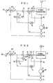
- Fig. 2 illustrates another embodiment of the present invention.
- Fig. 2 the embodiment is different from the Fig. 1 embodiment in that an output signal of a deviation calculating circuit 12 is multiplied by the current command signal I * in a multiplier 18 to obtain the current correction signal ⁇ I*.
- the current detection signal I of a rectifier 15 contains ripple components.
- the deivation calculating circuit 12 effects proportion and integration operations and the response may has a certain limitation if the input signal AI (current detection signal I) contains ripple components. For this reason, even if there is lag in response time in the deviation calculating circuit 12, the current correction signal AI * varies in proportion to the magnitude of the current command signal I * so that the response may be further improved than the Fig. 1 embodiment.
- Fig. 3 illustrates a further embodiment of the present invention, in which the armature current is decomposed into a component in the same direction as the magnetic flux of the field system and another component in the direction perpendicular to the first-mentioned direction.
- FIG. 3 the same reference numerals as used in Fig. 1 represent the same or similar parts or components.
- a current command circuit 19 is supplied with the current command signal I * performs the following calculation to obtain two perpendicularly intersecting components of the armature current, that is the parallel current component Id * which is parallel to the field magnetic flux and the perpendicular current component Iq * which is perpendicular to the former.
- 6 tan -1 k 1 I* k l : constant
- the perpendicular current component Iq * is applied to an adder 131 and a comparator 321, while the parallel current component Id * is applied to an adder 132 and a comparator 322.
- the position signals (three-phase signals) D detected for each phase by the position detector 4 are applied to a three-phase/two-phase converter circuit 22 so as to be converted into two-phase signals sinwt and coswt which are different from each other by 90 degrees in phase.
- the two-phase signals sinwt and coswt are applied to a current component detecting circuit 20 and a current pattern calculating circuit 21.
- the current detection signals (three-phase signals) detected for each phase by a current detector 16 are applied to a three-phase/two-phase converter circuit 23 so as to be converted into two-phase current detection signals ia, i ⁇ as shown by the following expressions: 6: phase difference w: rotation angular frequency
- the current component detecting circuit 20 receives the current detection signals ia, is and the two-phase signals sinwt and coswt and calculates the following equation to obtain the d-axis component Id and q-axis component Iq of the armature current:
- the current component detecting circuit 20 may attain the calculation of the equation (3) by using four multipliers.
- the component detection signal Iq and d-axis component detection signal Id detected by the current component detecting circuit 20 are applied to comparators 321 and 322 respectively so as to be compared with the q-axis component command signal Iq * and the d-axis component command signal Id * respectively.
- the current deviation signals ⁇ iq and Aid produced by the comparators 321 and 322 are applied to deviation calculating circuits 121 and 122 respectively so as to obtain the q-axis component correction signal ⁇ Iq* and d-axis component correction signal ⁇ Id* respectively.
- the q-axis component command signal Iq * and the q-axis component correction signal ⁇ Iq* are added to each other in the adder 131 so as to obtain the q-axis component corrected current command signal (Iq * + ⁇ Iq*), while the d-axis component command signal Id * and the d-axis component correction signal ⁇ Id* are added to each other in the adder 132 so as to obtain the d-axis component corrected current command signal (Id * + ⁇ Id*).
- the q-axis component and d-axis component current command signals are applied to the current pattern calculating circuit 21.
- the current pattern calculating circuit 21 receives the q-axis component and d-axis component current command signals and performs coordinate transformation to obtain AC current command signals ia * and is * in accordance with the following equation:
- the AC current command signals ia * and is * are converted into three-phase current pattern signals through a two-phase/three-phase converter circuit 24.
- the three-phase current pattern signals are generally illustrated as the current pattern signal i * for one pase.
- the current pattern signal i * is compared with the current detection signal i by the comparator 33 which produces the current deviation ⁇ i.
- the current deviation ⁇ i is applied to the current control circuit 17 which controls the power converter 2 by turning on/off the switching elements constituting the converter 2, in the same manner as in the Fig. 1 embodiment.
- Fig. 3 shows the control circuit only for one phase, control is made in the same manner for the other two phases.
- the desired effect can be obtained also in this embodiment in which the armature current of a synchronous motor is decomposed into a component parallel to the field magnetic flux and another component perpendicular to the former and these components are individually controlled to perform the motor control.
- the correction signal may be obtained by multiplying the q-axis component command signal Iq * by the q-axis component correction signal AIq * and multiplying the d-axis component command signal Id * by the q-axis component correction signal AId * , similarly to the Fig. 2 embodiment.
- Fig. 4 shows a still further embodiment, in which the present invention is applied to a control system in which an induction motor is driven by a power converter.
- Fig. 4 illustrates an example in which the primary current of an induction motor is decomposed into a torque component and an excitation component (constant value) so at these components are individually controlled.
- FIG. 4 the same numerals as used in Fig. 3 denote the same or similar parts or components, and an induction motor 6 is driven by a power converter 2.
- a velocity control circuit 11 receives the velocity command signal N * and the velocity detection signal N and produces the torque component command It * for the primary current.
- the torque component command It * is applied to an adder 131, a comparator 321 and a slip frequency calculating circuit 42.
- the excitation component command Im * produced from an excitation component command circuit 41 is applied to an adder 132 and a comparator 322..
- the slip frequency calculating circuit 42 calculates the slip frequency command ws * from the following equation (5).
- k 2 constant
- the slip frequency command ws * and the velocity detection signal N (which is proportional to the rotary frequency wr) are added to each other in an adder 43.
- the adder 43 produces the primary frequency command w l * which is applied to a two-phase oscillator 44.
- the two-phase oscillator 44 produces two-phase sinusoidal signals, sinw l t and cosw l t, with a frequency equal to the primary frequency command w l * and with a predetermined amplitude. These two-phase signals are applied to a current component detector circuit 45 and a current pattern calculating circuit 46.
- the current component detector circuit 45 receives the current detection signals ia and i ⁇ and of a three-phase/two-phase converter circuit 23 and the two-phase sinusoidal signals sinw 1 t and cosw 1 t and calculates the torque component It and the excitation component Im of the primary current i from the following equation:
- the current component detecting circuit 45 may be the same one as indicated by 20 in Fig. 3.
- the torque component It detected in the current component detecting circuit 45 is inputted to the comparator 321 and the excitation component Im is applied to the comparator 322.
- the current deviations ⁇ It and AIm respectively produced from the comparators 321 and 322 are applied to deviation calculating circuits 121 and 122 so as to derive the torque component correction signal ⁇ It * and the excitation component correction signal ⁇ It* respectively.
- An adder 131 adds the torque component command signal It * and the torque component correction signal ⁇ It* to each other so as to obtain the corrected torque current command signal (It * + ⁇ It*), while another adder 132 adds the excitation component command signal Im * and the excitation component correction signal ⁇ Im* to each other so as to obtain the corrected excitation current command signal (Im * + ⁇ Im * ).
- These corrected torque and excitation current command signals are applied to the current pattern calculating circuit 46 which in turn effects the coordinate transformation in accordance with the following equation so as to obtain the AC current command signals ia * and is * :
- the AC current command signals ia * and i ⁇ * are converted into three-phase AC current command signals through a two-phase/three-phase converter circuit 24.
- the three-phase AC current command signals are generally illustrated as the current pattern signal i * for one phase.
- the current pattern signal i * is compared with the current detection signal i by a comparator 33 which produces the current deviation ⁇ i.
- the current deviation ⁇ i is then applied to a current control circuit 17 which controls the power converter 2 by turning on/off the switching elemen- constituting the converter 2, thereby controllin the primary current.
- the desired effect can be obtained also in this embodiment in which the primary current of an induction motor is decomposed into a torque component and an excitation component so that these components are individually controlled.
- a current correction system is provided in each of the torque current control system and the excitation current control system in the Fig. 4 embodiment, it may be provided only in the torque current control system in the case the excitation component deviation AIm is small.
- the invention is of course applicable in the case the excitation component Im * is not maintained constant but arranged to be variable. In this case, however, it is necessary to cause the slip frequency calculating circuit to receive the torque component command It * and the excitation component command Im * so as to obtain the slip frequency ws.
- Fig. 5 shows another embodiment.
- the present invention is applied to an example in which the magnitude, the phase and the frequency of the primary current of an induction motor are individually commanded.
- the current command signal I 1 * is applied to an adder 13 and a comparator 32.
- the comparator 32 is further supplied with the current detection signal I 1 , which has been obtained in a rectifier 15, so as to produce the deviation ⁇ I 1 of the current detection signal I 1 from the current command signal I 1 *.
- the deviation ⁇ I 1 is applied to a deviation calculating circuit 12 which in turn produces and applies the current correction signal ⁇ I 1 * in accordance with the current deviation ⁇ I 1 to the adder 13.
- the adder 13 adds the current command signal I 1 * and the current correction signal ⁇ I 1 * to each other so as to produce and applies the corrected current command signal (I 1 * + ⁇ I 1 *) to a multiplier 14.
- a phase command circuit 52 receives the torque component command signal It * and produces the current phase command signal a * which is expressed as follows: k 3 : constant
- a two-phase oscillator 44 produces two-phase signals sin ⁇ 1 t and cos ⁇ 1 t of the same frequency as the primary frequency command ⁇ 1 and applies then to a phase shifter 53 in the same manner as in the Fig. 4 embodiment.
- the phase shifter 53 phase-shifts the two-phase signals sin ⁇ 1 t and cos ⁇ 1 t by the value corresponding to the current phase command signal a * so as to produce and applies the signals sin ( ⁇ 1 t + a * ) and cos ( ⁇ 1 t + a * ) to a two-phase/three phase converter circuit 54.
- the two-phase/three phase converter circuit 54 may be such as shown in Fig. 7 of U.S. Patent No. 3,824,437.
- the two-phase/three phase converter circuit 54 obtains the current reference signal ip for each phase and applied it to the mulitplier 14 individually provided for each phase.
- the multiplier 14 multiplies the corrected current command signal (i l * + ⁇ I 1 *) by the current reference signal ip so as to produce the current pattern signal i l * which is the current reference signal ip the amplitude of which varies in proportion to the corrected current command signal. Controlling the primary current of the induction motor 6 in accordance with the thus obtained current pattern signal i 1 *, it is possible to quickly make the primary current of the induction motor 6 agree with the current command signal I 1 * independently of the frequency response of the current control system including the current control circuit 17.
- the desired effect can be obtained also in this embodiment in which the magnitude, phase and frequency of the primary current of an induction motor is individually commanded so as to effect the velocity control.
- the Fig. 5 embodiment may of course be modified such that the product of the current command signal I 1 * and the current correction signal ⁇ I 1 * may be applied to the adder 13 similarly to the Fig. 2 embodiment.
- the current correction signal proportional to the current deviation is added to the current command signal so as to provide the target value of the motor current. Accordingly, it is possible to cause the magnitude of the motor current to always agree with the current command signal so as to produce desired torque.
Landscapes
- Engineering & Computer Science (AREA)
- Power Engineering (AREA)
- Control Of Ac Motors In General (AREA)
- Control Of Motors That Do Not Use Commutators (AREA)
Abstract
Description
- method and an The invention relates to a control/apparatus for an AC motor driven by a power converter, and in particular to an AC motor control apparatus having a current control system.
- An AC motor is driven by means of a power converter by controlling the motor current (instantaneous value) by turning on/off switching elements constituting the power converter. The motor current is controlled by the function of a current control system which operates on the basis of the relation between a given current command signal (AC signal) and a received current detection signal.
- There is of cource limitation in switching speed of the switching elements, such as thyristors, gate turn-off thyristors, constituting the power converter. The current control system controls the magnitude of the motor current by turning on/off the switching elements. Accordingly, there is limitation in frequency response in the current control system due to the limitation in switching speed of the switching elements, so that the system has inherent response delay. Calculating the frequency response in a current control system, it can be found that it is actually impossible to select the motor current to be large enough to be able to disregard the response delay when the AC motor is driven with its rated frequency.
- If there is such response delay in the current control system, the motor current becomes smaller than the current command value and the phase of the same lags, thereby causing inconvenience that the torque of the motor becomes insufficient, the motor speed drops, and the velocity control system becomes unstable. This becomes a serious problem as the operating frequency of the motor becomes higher.
- To solve such a problem, it has been known to provide, at the major side of a current control circuit, a current pattern calculating circuit for decomposing the motor current into a component in the same direction as the magnetic flux of the field system and another component in the direction perpendicular to the first-mentioned direction so as to obtain, by calculation, a current pattern signal necessary for generating desired torque. This is known, for example, by U.S. Patent No. 4,125,796, entitled "CONTROL APPARATUS FOR USE IN A SYNCHRONOUS MACHINE", particularly by Fig. 6 thereof.
- In the point of view of the stability in motor control, however, it is required to make more lagging the response of the current pattern calculation control system than that of the current control system. To control an AC motor, usually, a velocity control system is provided as a major loop. Thus, it is necessary to-ca-use-the response of the velocity control system to lag than that of the current pattern calculation control system. As the result, an avoidable problem is caused that the response of the velocity control system should be deteriorated. Further, there arises a practical problem that since three control systems are required to be provided, it is necessary to design these systems taking account of the stability of the whole system and correlating these three systems with each other, resulting in complexity in design, in adjusting, etc.
- An object of the invention is to provide an and a control method AC motor control apparatus, in which the motor torque can be controlled to a desired value with simple configuration and without lowering the response in velocity control.
- The present invention is featured in that a deviation of an actual motor current from a current command value is added to the current command value to obtain a corrected current command value which is supplied to a current control circuit.
- Other objects and features of the present invention will be apparent from the description which will be made hereunder in conjunction with appended drawings, in which:
- Fig. 1 is a block diagram illustrating the circuit configuration of an embodiment of the present invention;
- Fig. 2 is a block diagram illustrating the circuit configuration of another embodiment of the present invention;
- Fig. 3 is a block diagram illustrating the circuit configuration of a further embodiment of the present invention
- Fig. 4 is a block diagram illustrating the circuit configuration of a still further embodiment of the present invention; and
- Fig. 5 is a block diagram illustrating the circuit configuration of a different embodiment of the present invention.
- Fig. 1 shows an embodiment in which the present invention is applied to a control apparatus for driving a synchronous motor by using a power converter.
- In Fig. 1, a
synchronous motor 3 is driven by apower converter 2 and a field winding 3F thereof is excited by a not-shown power supply source. Thepower converter 2 converts an AC output of anAC source 1 into a variable frequency AC power and supplies it to thesynchronous motor 3. Mechanically directly coupled to a rotor of thepower converter 2 are aposition detector 4 for producing a position signal D (sinusoidal wave signal) corresponding to the relative position between field poles and an armature winding of thesynchronous motor 3 and avelocity detector 5 for detecting the rotational velocity of the same. The armature current of thesynchronous motor 3 is detected by acurrent detector 16. Acomparator 31 compares a velocity command signal N* of avelocity command circuit 10 with a velocity detection signal N of thevelocity detector 5 in the polarity as shown in the drawing. A velocity control circuit 11 is supplied with a velocity deviation AN and produces a current command signal I* instructing the magnitude of the armature current of thesynchronous motor 3. The armature current detected by acurrent detector 16 is then rectified by acurrent detector 15 to be a current detection signal I which is then compared by acomparator 32 with the current command signal I*. The current deviation signal AI, the output of thecomparator 32, is calculated in adeviation calculating circuit 12 and thereafter applied to anadder 13. Theadder 13 adds the current command signal I* and the current deviation AI and produces a corrected current command signal (I* ±ΔI*) which is then applied to amultiplier 14. Themultiplier 14 multiplies the position signal D by the corrected current command signal (I* ±ΔI*) to produce a current pattern signal i* (sinusoidal wave signal) which is the position signal D whose amplitude varies in proportion to the corrected current command signal. Acomparator 33 compares the current pattern signal i* with a current detection signal i (instantaneous value) detected by thecurrent detector 16 so as to produce the current deviation Δi therebetween which is then applied to acurrent control circuit 17. Thecurrent control circuit 17 applies a firing control signal for turning on/off switching elements constituting thepower converter 2, in accordance with the current deviation Ai. By the way, although a firing control circuit is provided usually between thecurrent control circuit 17 and thepower converter 2, it is omitted in the drawing on the assumption that it is incorporated within thepower converter 2 in this case. Further, although themultiplier 14, thecomparator 33, thecurrent detector 16, and thecurrent control circuit 17 are shown in the drawing only for one phase, theposition detector 4 produces three sets of position signals D for three phases in the case where, for example, thesynchronous motor 3 is a three phase machine and therefore, needless to say, three sets of themultipliers 14, thecomparators 33, thecurrent detectors 16, and thecurrent control circuits 17 be actually provided. - The operation of the apparatus will be next described. However, since the
deviation calculating circuit 12, theadder 13, therectifier 15, and thecomparator 32 are additionally provided, according to the present invention, to a known controll apparatus, the description of the operation of the known control apparatus per se is omitted. - The current command signal I* of the velocity control circuit 11 is used for instructing the magnitude of the armature current of the
synchronous motor 3. Therectifier 15 produces the current detection signal I which is proportional to the actual armature current. Thecomparator 32 compares the current detection signal I with the current command signal I* and produces the deviation ΔI therebetween which is then applied to thedeviation calculating circuit 12. Thedeviation calculating circuit 12 produces the current correction signal ΔI* which is proportional to the current deviation signal ΔI. The current command signal I* and the current correction signal ΔI* are added to each other in theadder 13 so as to supply the corrected current command signal (I* ±ΔI*) to themultiplier 14. Themultiplier 14 produces the current pattern signal i* which is the position signal D whose amplitude varies in proportion to the corrected current command signal. Thecurrent control circuit 17 controls the armature current of thesynchronous motor 3 so that it agrees with the current pattern signal i* by turning on/off switching elements constituting thepower converter 2, in accordance with the current deviation Ai of the current detection signal i from the current pattern signal i*. Thus, the armature current of thesynchronous motor 3 is controlled so as to agree with the position signal D in phase and agree with the current command signal I* in magnitude. - In this manner, if there is a current deviation ΔI of the armature current actually flowing in the
synchronous motor 3 from the current command signal I*, the current correction signal ΔI* which is proportional to the current deviation signal ΔI is added to the current command signal I* to obtain a desired value of the armature current. Thus, even if there is lag in frequency response in the current control system including thecurrent control circuit 17, it is possible to cause the magnitude of the armature current to always agree with the current command signal I*. At this time, the current correction control system including thedeviation calculating circuit 12 for producing the current correction signal ΔI* serves to operate as a supplementary system for the current control system. Accordingly, to determine the response of the velocity control system, it is not required to take account of the current correction control system and it is not necessary to lower the response of the velocity control system. As the result, the velocity control can be performed with high response and the design as well as adjustment of the control system can be easily attained. - Fig. 2 illustrates another embodiment of the present invention.
- In Fig. 2, the embodiment is different from the Fig. 1 embodiment in that an output signal of a
deviation calculating circuit 12 is multiplied by the current command signal I* in amultiplier 18 to obtain the current correction signal ΔI*. - In the Fig. 2 embodiment, the current correction signal ΔI* is expressed by ΔI* = I*·ΔI. That is, the current correction signal ΔI* varies in proportion to the magnitude of the current command signal I*. In this manner, the current control may be further improved in response.
- The current detection signal I of a
rectifier 15 contains ripple components. Thedeivation calculating circuit 12 effects proportion and integration operations and the response may has a certain limitation if the input signal AI (current detection signal I) contains ripple components. For this reason, even if there is lag in response time in thedeviation calculating circuit 12, the current correction signal AI* varies in proportion to the magnitude of the current command signal I* so that the response may be further improved than the Fig. 1 embodiment. - Fig. 3 illustrates a further embodiment of the present invention, in which the armature current is decomposed into a component in the same direction as the magnetic flux of the field system and another component in the direction perpendicular to the first-mentioned direction.
- In Fig. 3, the same reference numerals as used in Fig. 1 represent the same or similar parts or components. A
current command circuit 19 is supplied with the current command signal I* performs the following calculation to obtain two perpendicularly intersecting components of the armature current, that is the parallel current component Id* which is parallel to the field magnetic flux and the perpendicular current component Iq* which is perpendicular to the former.
- The perpendicular current component Iq* is applied to an
adder 131 and acomparator 321, while the parallel current component Id* is applied to anadder 132 and acomparator 322. - The position signals (three-phase signals) D detected for each phase by the
position detector 4 are applied to a three-phase/two-phase converter circuit 22 so as to be converted into two-phase signals sinwt and coswt which are different from each other by 90 degrees in phase. The two-phase signals sinwt and coswt are applied to a currentcomponent detecting circuit 20 and a currentpattern calculating circuit 21. The current detection signals (three-phase signals) detected for each phase by acurrent detector 16 are applied to a three-phase/two-phase converter circuit 23 so as to be converted into two-phase current detection signals ia, iβ as shown by the following expressions:
- The current
component detecting circuit 20 receives the current detection signals ia, is and the two-phase signals sinwt and coswt and calculates the following equation to obtain the d-axis component Id and q-axis component Iq of the armature current:
- The current
component detecting circuit 20 may attain the calculation of the equation (3) by using four multipliers. - The component detection signal Iq and d-axis component detection signal Id detected by the current
component detecting circuit 20 are applied tocomparators comparators deviation calculating circuits 121 and 122 respectively so as to obtain the q-axis component correction signal ΔIq* and d-axis component correction signal ΔId* respectively. The q-axis component command signal Iq* and the q-axis component correction signal ΔIq* are added to each other in theadder 131 so as to obtain the q-axis component corrected current command signal (Iq* + ΔIq*), while the d-axis component command signal Id* and the d-axis component correction signal ΔId* are added to each other in theadder 132 so as to obtain the d-axis component corrected current command signal (Id* + ΔId*). The q-axis component and d-axis component current command signals are applied to the currentpattern calculating circuit 21. The currentpattern calculating circuit 21 receives the q-axis component and d-axis component current command signals and performs coordinate transformation to obtain AC current command signals ia* and is* in accordance with the following equation:
phase converter circuit 24. In Fig. 3, the three-phase current pattern signals are generally illustrated as the current pattern signal i* for one pase. - The current pattern signal i* is compared with the current detection signal i by the
comparator 33 which produces the current deviation Δi. The current deviation Δi is applied to thecurrent control circuit 17 which controls thepower converter 2 by turning on/off the switching elements constituting theconverter 2, in the same manner as in the Fig. 1 embodiment. Although Fig. 3 shows the control circuit only for one phase, control is made in the same manner for the other two phases. Thus, it is possible to cause the magnitude of the armature current of thesynchronous motor 3 to agree with the current command signal I* independent of the frequency response in the current control system and to make the generated torque of thesynchronous motor 3 be a desired value. - Thus, the desired effect can be obtained also in this embodiment in which the armature current of a synchronous motor is decomposed into a component parallel to the field magnetic flux and another component perpendicular to the former and these components are individually controlled to perform the motor control.
- Alternatively, in the Fig. 3 embodiment, the correction signal may be obtained by multiplying the q-axis component command signal Iq* by the q-axis component correction signal AIq* and multiplying the d-axis component command signal Id* by the q-axis component correction signal AId*, similarly to the Fig. 2 embodiment.
- Fig. 4 shows a still further embodiment, in which the present invention is applied to a control system in which an induction motor is driven by a power converter.
- Fig. 4 illustrates an example in which the primary current of an induction motor is decomposed into a torque component and an excitation component (constant value) so at these components are individually controlled.
- In Fig. 4, the same numerals as used in Fig. 3 denote the same or similar parts or components, and an induction motor 6 is driven by a
power converter 2. A velocity control circuit 11 receives the velocity command signal N* and the velocity detection signal N and produces the torque component command It* for the primary current. The torque component command It* is applied to anadder 131, acomparator 321 and a slipfrequency calculating circuit 42. The excitation component command Im* produced from an excitation component command circuit 41 is applied to anadder 132 and acomparator 322.. Receiving the torque component command It*, the slipfrequency calculating circuit 42 calculates the slip frequency command ws* from the following equation (5).
- The slip frequency command ws* and the velocity detection signal N (which is proportional to the rotary frequency wr) are added to each other in an
adder 43. Theadder 43 produces the primary frequency command wl * which is applied to a two-phase oscillator 44. The two-phase oscillator 44 produces two-phase sinusoidal signals, sinwlt and coswlt, with a frequency equal to the primary frequency command wl * and with a predetermined amplitude. These two-phase signals are applied to a currentcomponent detector circuit 45 and a currentpattern calculating circuit 46. The currentcomponent detector circuit 45 receives the current detection signals ia and iβ and of a three-phase/two-phase converter circuit 23 and the two-phase sinusoidal signals sinw1t and cosw1t and calculates the torque component It and the excitation component Im of the primary current i from the following equation:
- The current
component detecting circuit 45 may be the same one as indicated by 20 in Fig. 3. - The torque component It detected in the current
component detecting circuit 45 is inputted to thecomparator 321 and the excitation component Im is applied to thecomparator 322. The current deviations ΔIt and AIm respectively produced from thecomparators deviation calculating circuits 121 and 122 so as to derive the torque component correction signal ΔIt* and the excitation component correction signal ΔIt* respectively. Anadder 131 adds the torque component command signal It* and the torque component correction signal ΔIt* to each other so as to obtain the corrected torque current command signal (It* + ΔIt*), while anotheradder 132 adds the excitation component command signal Im* and the excitation component correction signal ΔIm* to each other so as to obtain the corrected excitation current command signal (Im* + ΔIm*). These corrected torque and excitation current command signals are applied to the currentpattern calculating circuit 46 which in turn effects the coordinate transformation in accordance with the following equation so as to obtain the AC current command signals ia* and is*:
- The AC current command signals ia* and iβ* are converted into three-phase AC current command signals through a two-phase/three-
phase converter circuit 24. In Fig. 4, the three-phase AC current command signals are generally illustrated as the current pattern signal i* for one phase. - The current pattern signal i* is compared with the current detection signal i by a
comparator 33 which produces the current deviation Δi. The current deviation Δi is then applied to acurrent control circuit 17 which controls thepower converter 2 by turning on/off the switching elemen- constituting theconverter 2, thereby controllin the primary current. Thus, it is possible to control the magnitude of the primary current of theinduction motor 1 to be the value determined by the torque component command signal It* and the excitation component command signal Im* independently of the frequenc response of the current control system, enabling the generated torque of the induction motor 6 to be a desired value. - Thus, the desired effect can be obtained also in this embodiment in which the primary current of an induction motor is decomposed into a torque component and an excitation component so that these components are individually controlled.
- Further, although a current correction system is provided in each of the torque current control system and the excitation current control system in the Fig. 4 embodiment, it may be provided only in the torque current control system in the case the excitation component deviation AIm is small.
- Further, the invention is of course applicable in the case the excitation component Im* is not maintained constant but arranged to be variable. In this case, however, it is necessary to cause the slip frequency calculating circuit to receive the torque component command It* and the excitation component command Im* so as to obtain the slip frequency ws.
- Fig. 5 shows another embodiment.
- In the Fig. 5 embodiment, the present invention is applied to an example in which the magnitude, the phase and the frequency of the primary current of an induction motor are individually commanded.
- In Fig. 5, the same numerals as used in Fig. 4 denote the same or similar parts or components. In Fig. 5, the torque component command signal It* of a velocity control circuit 11 and the excitation component command Im* of an excitation component command circuit 41 are applied to a
current command circuit 51. Thecurrent command circuit 51 calculates the following equation to produce the current command signal I1 *:
- The current command signal I1* is applied to an
adder 13 and acomparator 32. Thecomparator 32 is further supplied with the current detection signal I1, which has been obtained in arectifier 15, so as to produce the deviation ΔI1 of the current detection signal I1 from the current command signal I1*. The deviation ΔI1 is applied to adeviation calculating circuit 12 which in turn produces and applies the current correction signal ΔI1* in accordance with the current deviation ΔI1 to theadder 13. Theadder 13 adds the current command signal I1* and the current correction signal ΔI1* to each other so as to produce and applies the corrected current command signal (I1* + ΔI1*) to amultiplier 14. - A
phase command circuit 52 receives the torque component command signal It* and produces the current phase command signal a* which is expressed as follows:
- A two-
phase oscillator 44 produces two-phase signals sinω1t and cosω1t of the same frequency as the primary frequency command ω1 and applies then to aphase shifter 53 in the same manner as in the Fig. 4 embodiment. Thephase shifter 53 phase-shifts the two-phase signals sinω1t and cosω1t by the value corresponding to the current phase command signal a* so as to produce and applies the signals sin (ω1t + a*) and cos (ω1t + a*) to a two-phase/three phase converter circuit 54. The two-phase/three phase converter circuit 54 may be such as shown in Fig. 7 of U.S. Patent No. 3,824,437. The two-phase/three phase converter circuit 54 obtains the current reference signal ip for each phase and applied it to themulitplier 14 individually provided for each phase. Themultiplier 14 multiplies the corrected current command signal (il * + ΔI1*) by the current reference signal ip so as to produce the current pattern signal il * which is the current reference signal ip the amplitude of which varies in proportion to the corrected current command signal. Controlling the primary current of the induction motor 6 in accordance with the thus obtained current pattern signal i1*, it is possible to quickly make the primary current of the induction motor 6 agree with the current command signal I1 * independently of the frequency response of the current control system including thecurrent control circuit 17. - Thus, the desired effect can be obtained also in this embodiment in which the magnitude, phase and frequency of the primary current of an induction motor is individually commanded so as to effect the velocity control.
- Alternatively, the Fig. 5 embodiment may of course be modified such that the product of the current command signal I1 * and the current correction signal ΔI1* may be applied to the
adder 13 similarly to the Fig. 2 embodiment. - As described above, according to the present invention, if the armature current actually flowing in an AC motor deviates from the current command signal, the current correction signal proportional to the current deviation is added to the current command signal so as to provide the target value of the motor current. Accordingly, it is possible to cause the magnitude of the motor current to always agree with the current command signal so as to produce desired torque.
- Further, in order to determine the response of the control system for producing the current command signal, it is not necessary to account of the current correction control system for obtaining the current correction signal, resulting in simplification in design and adjustment of the control system.
- Although analog configuration is employed in the embodiments described above, the present invention may of course be applied to the case where desital controls are performed by using such as a microprocesser.
Claims (6)
in which said apparatus further comprises;
Applications Claiming Priority (2)
| Application Number | Priority Date | Filing Date | Title |
|---|---|---|---|
| JP5017/82 | 1982-01-18 | ||
| JP57005017A JPS58123394A (en) | 1982-01-18 | 1982-01-18 | Controller for ac motor |
Publications (3)
| Publication Number | Publication Date |
|---|---|
| EP0084367A2 true EP0084367A2 (en) | 1983-07-27 |
| EP0084367A3 EP0084367A3 (en) | 1984-02-15 |
| EP0084367B1 EP0084367B1 (en) | 1986-11-12 |
Family
ID=11599751
Family Applications (1)
| Application Number | Title | Priority Date | Filing Date |
|---|---|---|---|
| EP83100348A Expired EP0084367B1 (en) | 1982-01-18 | 1983-01-17 | Method and apparatus for controlling an ac motor |
Country Status (4)
| Country | Link |
|---|---|
| US (1) | US4451771A (en) |
| EP (1) | EP0084367B1 (en) |
| JP (1) | JPS58123394A (en) |
| DE (1) | DE3367708D1 (en) |
Cited By (6)
| Publication number | Priority date | Publication date | Assignee | Title |
|---|---|---|---|---|
| EP0171617A1 (en) * | 1984-07-27 | 1986-02-19 | Siemens Aktiengesellschaft | Method and device to operate an indirect converter with limitation of the surge current |
| EP0177060A1 (en) * | 1984-10-05 | 1986-04-09 | Hitachi, Ltd. | Digital servo-control system |
| EP0201872A2 (en) * | 1985-05-13 | 1986-11-20 | General Electric Company | Flux-weakening regime operation of an interior permanent magnet sychronous motor |
| EP0373227A1 (en) * | 1988-04-21 | 1990-06-20 | Fanuc Ltd. | Current control device for pwm control |
| WO1990015472A1 (en) * | 1989-05-31 | 1990-12-13 | Siemens Aktiengesellschaft | Process for compensating a phase and amplitude cycle between a multi-phase actual and set value and circuit for implementing the process |
| GB2201815B (en) * | 1987-02-27 | 1991-03-27 | Gen Electric | Ac motor speed controller. |
Families Citing this family (36)
| Publication number | Priority date | Publication date | Assignee | Title |
|---|---|---|---|---|
| JPS5963998A (en) * | 1982-10-04 | 1984-04-11 | Hitachi Ltd | Controlling method for induction motor |
| JPS5972991A (en) * | 1982-10-19 | 1984-04-25 | Fanuc Ltd | Controller for motor |
| JPS59156184A (en) * | 1983-02-23 | 1984-09-05 | Hitachi Ltd | Controlling method of induction motor |
| US4763057A (en) * | 1983-12-30 | 1988-08-09 | Kollmorgen Technologies Corporation | Control for improving induction transient response by excitation angle control |
| EP0175154B1 (en) * | 1984-08-21 | 1991-11-06 | Hitachi, Ltd. | Method of controlling inverter-driven induction motor |
| JPS6152179A (en) * | 1984-08-22 | 1986-03-14 | Toshiba Corp | Power source for driving motor |
| WO1986001654A1 (en) * | 1984-08-30 | 1986-03-13 | Fanuc Ltd | System for digitally controlling an induction motor |
| JPS6277081A (en) * | 1985-09-10 | 1987-04-09 | Nikki Denso Kk | Controlling device for 3-phase induction motor |
| JPH07118950B2 (en) * | 1986-04-14 | 1995-12-18 | 株式会社日立製作所 | PWM inverter control method and apparatus |
| JPS6331492A (en) * | 1986-07-25 | 1988-02-10 | Nippon Electric Ind Co Ltd | Controller for induction motor |
| US4716348A (en) * | 1986-08-26 | 1987-12-29 | Magnetek, Inc. | DC motor adaptive controller |
| US4885518A (en) * | 1987-08-21 | 1989-12-05 | Westinghouse Electric Corp. | Induction motor torque/flux control system |
| US5003243A (en) * | 1987-09-29 | 1991-03-26 | Kabushiki Kaisha Toshiba | Control apparatus for induction machine |
| US5140248A (en) * | 1987-12-23 | 1992-08-18 | Allen-Bradley Company, Inc. | Open loop motor control with both voltage and current regulation |
| JP2708479B2 (en) * | 1988-07-22 | 1998-02-04 | 株式会社日立製作所 | Control device for AC servomotor |
| US4987358A (en) * | 1989-04-21 | 1991-01-22 | Branam Timothy R | Electronic torque switch |
| US5047699A (en) * | 1989-06-26 | 1991-09-10 | Sundstrand Corporation | VSCF start system motor current estimator |
| US4982145A (en) * | 1989-09-08 | 1991-01-01 | Aeg Westinghouse Industrial Automation Corporation | Method and apparatus for the optimization of thyristor power supply transport time delay |
| US4958117A (en) * | 1989-09-29 | 1990-09-18 | Allen-Bradley Company, Inc. | Frequency control based on sensing voltage fed to an induction motor |
| JPH03139192A (en) * | 1989-10-23 | 1991-06-13 | Mitsubishi Electric Corp | Motor controller |
| JP3331734B2 (en) * | 1993-05-18 | 2002-10-07 | 株式会社明電舎 | Control method of rotating electric machine |
| US5502360A (en) * | 1995-03-10 | 1996-03-26 | Allen-Bradley Company, Inc. | Stator resistance detector for use in electric motor controllers |
| JP3709239B2 (en) * | 1996-04-26 | 2005-10-26 | ファナック株式会社 | Magnetic saturation correction method for AC servo motor |
| US6008617A (en) * | 1996-05-20 | 1999-12-28 | Hitachi, Ltd. | Motor control device for high frequency AC driven motor |
| JP3321356B2 (en) * | 1996-05-20 | 2002-09-03 | 株式会社日立製作所 | Motor control device and control device for electric vehicle |
| JP2001238499A (en) * | 2000-02-24 | 2001-08-31 | Hitachi Ltd | Speed control method of induction motor |
| KR100371370B1 (en) * | 2000-08-18 | 2003-02-06 | 엘지산전 주식회사 | Vector control apparatus |
| FI112414B (en) * | 2001-03-19 | 2003-11-28 | Abb Industry Oy | Procedure in conjunction with an inverter |
| JP4455075B2 (en) * | 2004-01-28 | 2010-04-21 | 三菱電機株式会社 | Motor control device |
| DE102005048330A1 (en) * | 2005-10-08 | 2007-04-19 | Daimlerchrysler Ag | Drive system for an electric machine |
| JP4816257B2 (en) * | 2006-05-31 | 2011-11-16 | 日本精工株式会社 | Motor control device |
| JP5259077B2 (en) * | 2006-12-04 | 2013-08-07 | 株式会社京三製作所 | Instantaneous voltage drop compensation circuit, power converter, instantaneous voltage drop compensation method, and instantaneous voltage drop compensation program |
| EP1944862B1 (en) * | 2007-01-15 | 2011-08-03 | Hitachi Industrial Equipment Systems Co., Ltd. | Induction motor controller |
| JP4952359B2 (en) * | 2007-04-25 | 2012-06-13 | アイシン精機株式会社 | Electric motor control device, control method, and computer program |
| JP6084863B2 (en) * | 2013-02-28 | 2017-02-22 | 川崎重工業株式会社 | Power converter for grid connection |
| RU2599529C1 (en) * | 2015-11-17 | 2016-10-10 | Федеральное государственное автономное образовательное учреждение высшего образования "Южно-Уральский государственный университет (национальный исследовательский университет)" (ФГАОУ ВО "ЮУрГУ (НИУ)") | Device for frequency control over asynchronous electric drive |
Citations (3)
| Publication number | Priority date | Publication date | Assignee | Title |
|---|---|---|---|---|
| DE2734430B2 (en) * | 1976-07-30 | 1979-06-28 | Hitachi, Ltd., Tokio | Arrangement for regulating the speed of a synchronous motor |
| US4240020A (en) * | 1977-07-04 | 1980-12-16 | Hitachi, Ltd. | Control system for suppressing torque ripple in synchronous motor |
| DE2915987A1 (en) * | 1979-04-20 | 1981-02-26 | Bosch Gmbh Robert | NC machine tool fast reacting servo drive - uses phase signals corresp. to rotary angle of sync. machine to control current |
Family Cites Families (10)
| Publication number | Priority date | Publication date | Assignee | Title |
|---|---|---|---|---|
| US3824437A (en) * | 1969-08-14 | 1974-07-16 | Siemens Ag | Method for controlling asynchronous machines |
| JPS5396423A (en) * | 1977-02-01 | 1978-08-23 | Mitsubishi Electric Corp | Control system for induction motor |
| US4358722A (en) * | 1977-08-17 | 1982-11-09 | Kabushiki Kaisha Yaskawa Denki Seisakusho | Speed detector using resolver |
| JPS5534854A (en) * | 1978-09-04 | 1980-03-11 | Hitachi Ltd | Controlling method of secondary winding-exciting motor |
| JPS5928146B2 (en) * | 1978-11-04 | 1984-07-11 | ファナック株式会社 | Induction motor drive control method |
| JPS6016195B2 (en) * | 1979-06-08 | 1985-04-24 | 富士電機株式会社 | DC motor control device |
| US4330741A (en) * | 1979-06-20 | 1982-05-18 | Hitachi, Ltd. | Electric control apparatus of induction motor |
| US4320331A (en) * | 1979-10-01 | 1982-03-16 | General Electric Company | Transistorized current controlled pulse width modulated inverter machine drive system |
| US4314190A (en) * | 1980-04-22 | 1982-02-02 | General Electric Company | Controlled current inverter with angle command limit |
| DE3026202A1 (en) * | 1980-07-10 | 1982-02-04 | Siemens AG, 1000 Berlin und 8000 München | TURNFIELD MACHINE DRIVE WITH A CONVERTER-DRIVEN TURNFIELD MACHINE AND A CONVERTER CONTROLLER CONNECTED WITH TWO AC VOLTAGE INTEGRATORS AND A COMPUTER MODEL CIRCUIT |
-
1982
- 1982-01-18 JP JP57005017A patent/JPS58123394A/en active Pending
-
1983
- 1983-01-14 US US06/458,057 patent/US4451771A/en not_active Expired - Lifetime
- 1983-01-17 EP EP83100348A patent/EP0084367B1/en not_active Expired
- 1983-01-17 DE DE8383100348T patent/DE3367708D1/en not_active Expired
Patent Citations (3)
| Publication number | Priority date | Publication date | Assignee | Title |
|---|---|---|---|---|
| DE2734430B2 (en) * | 1976-07-30 | 1979-06-28 | Hitachi, Ltd., Tokio | Arrangement for regulating the speed of a synchronous motor |
| US4240020A (en) * | 1977-07-04 | 1980-12-16 | Hitachi, Ltd. | Control system for suppressing torque ripple in synchronous motor |
| DE2915987A1 (en) * | 1979-04-20 | 1981-02-26 | Bosch Gmbh Robert | NC machine tool fast reacting servo drive - uses phase signals corresp. to rotary angle of sync. machine to control current |
Non-Patent Citations (1)
| Title |
|---|
| Patent Abstracts of Japan vol. 2, no. 130, 28 October 1978 page 8036E78 & JP-A-53-99410 * |
Cited By (10)
| Publication number | Priority date | Publication date | Assignee | Title |
|---|---|---|---|---|
| EP0171617A1 (en) * | 1984-07-27 | 1986-02-19 | Siemens Aktiengesellschaft | Method and device to operate an indirect converter with limitation of the surge current |
| EP0177060A1 (en) * | 1984-10-05 | 1986-04-09 | Hitachi, Ltd. | Digital servo-control system |
| US4712052A (en) * | 1984-10-05 | 1987-12-08 | Hitachi, Ltd. | Digital servo-control system |
| EP0201872A2 (en) * | 1985-05-13 | 1986-11-20 | General Electric Company | Flux-weakening regime operation of an interior permanent magnet sychronous motor |
| EP0201872A3 (en) * | 1985-05-13 | 1987-08-26 | General Electric Company | Flux-weakening regime operation of an interior permanent magnet sychronous motor |
| GB2201815B (en) * | 1987-02-27 | 1991-03-27 | Gen Electric | Ac motor speed controller. |
| EP0373227A1 (en) * | 1988-04-21 | 1990-06-20 | Fanuc Ltd. | Current control device for pwm control |
| EP0373227A4 (en) * | 1988-04-21 | 1992-01-08 | Fanuc Ltd. | Current control device for pwm control |
| WO1990015472A1 (en) * | 1989-05-31 | 1990-12-13 | Siemens Aktiengesellschaft | Process for compensating a phase and amplitude cycle between a multi-phase actual and set value and circuit for implementing the process |
| US5307259A (en) * | 1989-05-31 | 1994-04-26 | Siemens Aktiengesellschaft | Process for compensating a phase and amplitude response between a multiphase setpoint and actual value and circuit for implementing the process |
Also Published As
| Publication number | Publication date |
|---|---|
| US4451771A (en) | 1984-05-29 |
| EP0084367B1 (en) | 1986-11-12 |
| EP0084367A3 (en) | 1984-02-15 |
| DE3367708D1 (en) | 1987-01-02 |
| JPS58123394A (en) | 1983-07-22 |
Similar Documents
| Publication | Publication Date | Title |
|---|---|---|
| EP0084367B1 (en) | Method and apparatus for controlling an ac motor | |
| US4361791A (en) | Apparatus for controlling a PWM inverter-permanent magnet synchronous motor drive | |
| KR100354775B1 (en) | Speed control apparatus of a synchronous reluctance motor | |
| US7671558B2 (en) | Induction motor controller | |
| EP0117514B1 (en) | Method for controlling induction motor and apparatus therefor | |
| JPS5850119B2 (en) | Control device for commutatorless motor | |
| US4132931A (en) | Control system for a.c. motors | |
| US4060753A (en) | Control system for commutatorless motor | |
| US4088932A (en) | Control system for commutatorless motor | |
| JPH0828972B2 (en) | Non-circulating current type cycloconverter control device | |
| US4527109A (en) | Control apparatus for thyristor motor | |
| JPS5949797B2 (en) | AC machine current control method | |
| JPH0884500A (en) | Speed sensorless vector controller for induction motor | |
| JP3770286B2 (en) | Vector control method for induction motor | |
| JPH0344509B2 (en) | ||
| JP2590524B2 (en) | Vector controller | |
| SU1108597A2 (en) | Electric drive with asynchronous phase-wound rotor motor | |
| JPH0561876B2 (en) | ||
| JPH0667256B2 (en) | Cycloconverter control device | |
| JPH0412698A (en) | Control method for voltage type pwm inverter | |
| JPH0213555B2 (en) | ||
| JPH0538143A (en) | Controller of cyclo converter | |
| JP2594917B2 (en) | Power converter control device | |
| JPS6332032B2 (en) | ||
| JPS5923193B2 (en) | Synchronous motor control device |
Legal Events
| Date | Code | Title | Description |
|---|---|---|---|
| PUAI | Public reference made under article 153(3) epc to a published international application that has entered the european phase |
Free format text: ORIGINAL CODE: 0009012 |
|
| AK | Designated contracting states |
Designated state(s): DE FR GB |
|
| PUAL | Search report despatched |
Free format text: ORIGINAL CODE: 0009013 |
|
| AK | Designated contracting states |
Designated state(s): DE FR GB |
|
| 17P | Request for examination filed |
Effective date: 19840220 |
|
| GRAA | (expected) grant |
Free format text: ORIGINAL CODE: 0009210 |
|
| AK | Designated contracting states |
Kind code of ref document: B1 Designated state(s): DE FR GB |
|
| REF | Corresponds to: |
Ref document number: 3367708 Country of ref document: DE Date of ref document: 19870102 |
|
| ET | Fr: translation filed | ||
| PLBE | No opposition filed within time limit |
Free format text: ORIGINAL CODE: 0009261 |
|
| STAA | Information on the status of an ep patent application or granted ep patent |
Free format text: STATUS: NO OPPOSITION FILED WITHIN TIME LIMIT |
|
| 26N | No opposition filed | ||
| PGFP | Annual fee paid to national office [announced via postgrant information from national office to epo] |
Ref country code: FR Payment date: 19961218 Year of fee payment: 15 |
|
| PGFP | Annual fee paid to national office [announced via postgrant information from national office to epo] |
Ref country code: GB Payment date: 19970102 Year of fee payment: 15 |
|
| PGFP | Annual fee paid to national office [announced via postgrant information from national office to epo] |
Ref country code: DE Payment date: 19970327 Year of fee payment: 15 |
|
| PG25 | Lapsed in a contracting state [announced via postgrant information from national office to epo] |
Ref country code: GB Free format text: LAPSE BECAUSE OF NON-PAYMENT OF DUE FEES Effective date: 19980117 |
|
| PG25 | Lapsed in a contracting state [announced via postgrant information from national office to epo] |
Ref country code: FR Free format text: THE PATENT HAS BEEN ANNULLED BY A DECISION OF A NATIONAL AUTHORITY Effective date: 19980131 |
|
| GBPC | Gb: european patent ceased through non-payment of renewal fee |
Effective date: 19980117 |
|
| PG25 | Lapsed in a contracting state [announced via postgrant information from national office to epo] |
Ref country code: DE Free format text: LAPSE BECAUSE OF NON-PAYMENT OF DUE FEES Effective date: 19981001 |
|
| REG | Reference to a national code |
Ref country code: FR Ref legal event code: ST |