EP0084232A1 - Filter circuits for reducing vibration sensitivity in vortex shedding flowmeter signal generators - Google Patents
Filter circuits for reducing vibration sensitivity in vortex shedding flowmeter signal generators Download PDFInfo
- Publication number
- EP0084232A1 EP0084232A1 EP82306580A EP82306580A EP0084232A1 EP 0084232 A1 EP0084232 A1 EP 0084232A1 EP 82306580 A EP82306580 A EP 82306580A EP 82306580 A EP82306580 A EP 82306580A EP 0084232 A1 EP0084232 A1 EP 0084232A1
- Authority
- EP
- European Patent Office
- Prior art keywords
- signal
- vibration signal
- vibration
- switches
- filter circuit
- Prior art date
- Legal status (The legal status is an assumption and is not a legal conclusion. Google has not performed a legal analysis and makes no representation as to the accuracy of the status listed.)
- Granted
Links
- 230000035945 sensitivity Effects 0.000 title claims description 4
- 239000003990 capacitor Substances 0.000 claims abstract description 13
- 101150087426 Gnal gene Proteins 0.000 claims 1
- 238000010586 diagram Methods 0.000 description 2
- 230000003321 amplification Effects 0.000 description 1
- 230000005540 biological transmission Effects 0.000 description 1
- 230000000694 effects Effects 0.000 description 1
- 230000008030 elimination Effects 0.000 description 1
- 238000003379 elimination reaction Methods 0.000 description 1
- 238000004519 manufacturing process Methods 0.000 description 1
- 238000000034 method Methods 0.000 description 1
- 238000003199 nucleic acid amplification method Methods 0.000 description 1
Images
Classifications
-
- G—PHYSICS
- G01—MEASURING; TESTING
- G01F—MEASURING VOLUME, VOLUME FLOW, MASS FLOW OR LIQUID LEVEL; METERING BY VOLUME
- G01F1/00—Measuring the volume flow or mass flow of fluid or fluent solid material wherein the fluid passes through a meter in a continuous flow
- G01F1/05—Measuring the volume flow or mass flow of fluid or fluent solid material wherein the fluid passes through a meter in a continuous flow by using mechanical effects
- G01F1/20—Measuring the volume flow or mass flow of fluid or fluent solid material wherein the fluid passes through a meter in a continuous flow by using mechanical effects by detection of dynamic effects of the flow
- G01F1/32—Measuring the volume flow or mass flow of fluid or fluent solid material wherein the fluid passes through a meter in a continuous flow by using mechanical effects by detection of dynamic effects of the flow using swirl flowmeters
- G01F1/325—Means for detecting quantities used as proxy variables for swirl
- G01F1/3287—Means for detecting quantities used as proxy variables for swirl circuits therefor
Definitions
- This invention relates to filter circuits for reducing vibration sensitivity (and noise) in vortex shedding flowmeter signal generators.
- vortex shedding sensors or transmitters are particularly sensitive to vibrations. Such vibrations are sometimes misinterpreted as the vortex shedding frequency or at least represent noise and obstruction to receiving the true vortex shedding frequency.
- a filter circuit for reducing vibration sensitivity in a vortex shedding flowmeter signal generator producing a vortex shedding frequency signal the filter circuit being characterised by:
- a filter circuit forming a preferred embodiment of the present invention and described hereinbelow processes a vibration signal and subtracts it from the vortex shedding frequency signal to provide a shedding frequency signal with reduced or eliminated noise.
- the preferred circuit includes a separate vibration sensor with preamplifier for sensing vibration in the flow stream.
- a vibration signal is provided through a phased locked loop and counter to a channel multiplexer circuit which selectively and sequentially applies a voltage from different sequential parts of the vibration signal to a plurality of capacitors.
- the vortex sensor signal is provided through the multiplexer circuitry wherein the vibration signal at each instant is subtracted from the vortex shedding frequency signal to provide a substantially noise reduced output signal for further amplification.
- the preferred circuit is simple in design and economical to manufacture.
- a connecting line 20 is connected across output lines 22 and 24 respectively of the vortex sensor preamplifier 12 and the vibration sensor preamplifier 16.
- a selector switch S A is manually or automatically operable to select one of the output lines 20 or 24 and connect it to a phase locked loop 30.
- the output line 24 from the vibration sensor preamplifier 16 is shown connected to the loop 30.
- the phase locked loop 30, for example a CA4046B, is connected to the output line 24 of the vibration sensor which maintains a signal in known fashion in case the signal disappears.
- the phase locked loop 30 thus locks into the vibration signal and generates a control signal for tracking a notch filter that is in synchronism with the undesired vibration signal component.
- the vibration signal is multiplied by a number n equal to the number of switches S 1 to S n in a multiplexer 36. This multiplication takes place in the phase locked loop 30 using known circuit components.
- An output of the phase locked loop 30 is connected to a divide-by-n counter 32 which is, for example, a CA4520B.
- the counter 32 divides the signal by the value n and provides it over digital output lines 34 to the multiplexer 36.
- the multiplexer 36 operates to sequentially close the switches S l to S n during a single period of the vibration frequency. If there is no single vibration frequency, the period is divided by the fundamental frequency component of the vibration signal.
- Each of a plurality of capacitors C 1 to C n connected in series with the respective switches S 1 to S n is thus supplied with an average voltage value from the signal during each time increment during which its corresponding switch is closed. Since the capacitors C 1 to C n are in series with the vortex sensor signal coming from the line 22, through suitable and known electronic circuitry, the capacitor voltage is subtracted from the vortex shedding frequency signal.
- the multiplexer 36 comprising the switches S 1 to S n is exemplified by a CD4067B integrated circuit multiplexer.
- Figure 2 shows one period of the fundamental vibration signal 44 whose voltage varies over a total period T.
- the total period is divided by n into time increments dt.
- the average voltage V 1 to V n for each time increment is applied to its corresponding capacitor C 1 to C n by sequential operation of the respective switches S 1 to S n .
- the vibration in the flow is sometimes sufficiently great to produce a vibration signal in the vortex sensor 10 itself and, when this is the case, the switch SA can be switched over to connect to line 20 and provide the vibration signal to the phase locked loop circuit 30.
- the amplifier 40 at the output of the notch filter converts the vortex signal currents in the capacitors C 1 to C n to a voltage type signal to drive following circuitry (not shown).
- the time constant of the resistor R 1 and the capacitors taken individually determines the average of the signal and the bandwidth of the notch. These are chosen typically so that 1/2 ⁇ R 1 C is less than one tenth of the vibration signal to be removed. Also, this determines the lower limit of the desired vortex signal to be amplified. That is, the lower cutoff will be determined by 1/2 ⁇ R 1 C where C is the value of the individual capacitors C 1 to C n .
- An important feature of this apparatus is the tracking of the notch filter to the vibration signal and the sequential elimination of a major portion of the undesired vibration effects by the output of the vortex shedding flow sensor or transmitter.
Landscapes
- Physics & Mathematics (AREA)
- Fluid Mechanics (AREA)
- General Physics & Mathematics (AREA)
- Measuring Volume Flow (AREA)
Abstract
Description
- This invention relates to filter circuits for reducing vibration sensitivity (and noise) in vortex shedding flowmeter signal generators.
- The operation of vortex shedding flowmeters is known and exemplified by US Patent No. 4 026 150 (Schmidt). It is known that when a non-streamlined obstacle or bluff body is placed in a flow stream vortices are produced which alternate from one side to the opposite side of the obstruction. The vortices are produced at a frequency which is directly proportional to the volumetric flow rate.
- It is also known to direct a vortex shedding frequency through a preamplifier to processing circuitry, and through a two wire transmission line to a remote station for determining the flow rate. Such circuitry is exemplified in US Patents Nos. 4 134 297 (Herzl), 4 094 194 (Herzl) and 4 123 940 (Herzl et al).
- It is known that vortex shedding sensors or transmitters are particularly sensitive to vibrations. Such vibrations are sometimes misinterpreted as the vortex shedding frequency or at least represent noise and obstruction to receiving the true vortex shedding frequency.
- According to the present invention there is provided a filter circuit for reducing vibration sensitivity in a vortex shedding flowmeter signal generator producing a vortex shedding frequency signal, the filter circuit being characterised by:
- means for providing a vibration signal having a fundamental frequency with a vibration signal period;
- a phase locked loop connected for receiving the vibration signal and multiplying the vibration signal by a selected number;
- dividing means connected to an output of the phased locked loop for dividing the vibration signal by a selected number;
- multiplexer means connected to the dividing means for sequentially preserving the average voltage of each sequential time increment of the vibration signal period, the vibration signal period being divided into a number of increments equal to the selected number; and
- means for subtracting each average voltage from the vortex shedding frequency signal during each respective time increment.
- A filter circuit forming a preferred embodiment of the present invention and described hereinbelow processes a vibration signal and subtracts it from the vortex shedding frequency signal to provide a shedding frequency signal with reduced or eliminated noise. The preferred circuit includes a separate vibration sensor with preamplifier for sensing vibration in the flow stream. A vibration signal is provided through a phased locked loop and counter to a channel multiplexer circuit which selectively and sequentially applies a voltage from different sequential parts of the vibration signal to a plurality of capacitors. The vortex sensor signal is provided through the multiplexer circuitry wherein the vibration signal at each instant is subtracted from the vortex shedding frequency signal to provide a substantially noise reduced output signal for further amplification. The preferred circuit is simple in design and economical to manufacture.
- The invention will now be further described, by way of illustrative and non-limiting example, with reference to the accompanying drawing, in which:
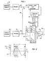
- Figure 1 is a block schematic diagram of a filter circuit embodying the invention; and
- Figure 2 is a waveform diagram showing the application of voltages to various capacitors of the circuit of Figure 1.
- Figure 1 of the drawings shows a
vortex sensor 10, apreamplifier 12 for amplifying a vortex shedding frequency from the vortex sensor, avibration sensor 14, and a preamplifier 16 for amplifying a vibration signal from the vibration sensor. Theelements - A connecting line 20 is connected across
output lines vortex sensor preamplifier 12 and the vibration sensor preamplifier 16. A selector switch SA is manually or automatically operable to select one of theoutput lines 20 or 24 and connect it to a phase lockedloop 30. Theoutput line 24 from the vibration sensor preamplifier 16 is shown connected to theloop 30. The phase lockedloop 30, for example a CA4046B, is connected to theoutput line 24 of the vibration sensor which maintains a signal in known fashion in case the signal disappears. The phase lockedloop 30 thus locks into the vibration signal and generates a control signal for tracking a notch filter that is in synchronism with the undesired vibration signal component. - The vibration signal is multiplied by a number n equal to the number of switches S1 to Sn in a
multiplexer 36. This multiplication takes place in the phase lockedloop 30 using known circuit components. - An output of the phase locked
loop 30 is connected to a divide-by-n counter 32 which is, for example, a CA4520B. The counter 32 divides the signal by the value n and provides it overdigital output lines 34 to themultiplexer 36. Themultiplexer 36 operates to sequentially close the switches Sl to Sn during a single period of the vibration frequency. If there is no single vibration frequency, the period is divided by the fundamental frequency component of the vibration signal. - Each of a plurality of capacitors C1 to Cn connected in series with the respective switches S1 to Sn is thus supplied with an average voltage value from the signal during each time increment during which its corresponding switch is closed. Since the capacitors C1 to Cn are in series with the vortex sensor signal coming from the
line 22, through suitable and known electronic circuitry, the capacitor voltage is subtracted from the vortex shedding frequency signal. - This leaves only the desired vortex shedding frequency signal at an output resistor R,, which signal is amplified by an operational amplifier 40 (having a feedback resistor 42) in known fashion to produce a vortex shedding frequency output signal at a
terminal 42. - The
multiplexer 36 comprising the switches S1 to Sn is exemplified by a CD4067B integrated circuit multiplexer. - Figure 2 shows one period of the fundamental vibration signal 44 whose voltage varies over a total period T. The total period is divided by n into time increments dt. The average voltage V1 to Vn for each time increment is applied to its corresponding capacitor C1 to Cn by sequential operation of the respective switches S1 to Sn.
- The vibration in the flow is sometimes sufficiently great to produce a vibration signal in the
vortex sensor 10 itself and, when this is the case, the switch SA can be switched over to connect to line 20 and provide the vibration signal to the phase lockedloop circuit 30. - The
amplifier 40 at the output of the notch filter converts the vortex signal currents in the capacitors C1 to Cn to a voltage type signal to drive following circuitry (not shown). The time constant of the resistor R1 and the capacitors taken individually determines the average of the signal and the bandwidth of the notch. These are chosen typically so that 1/2 π R1C is less than one tenth of the vibration signal to be removed. Also, this determines the lower limit of the desired vortex signal to be amplified. That is, the lower cutoff will be determined by 1/2 π R1C where C is the value of the individual capacitors C1 to Cn. - An important feature of this apparatus is the tracking of the notch filter to the vibration signal and the sequential elimination of a major portion of the undesired vibration effects by the output of the vortex shedding flow sensor or transmitter.
Claims (5)
Applications Claiming Priority (2)
| Application Number | Priority Date | Filing Date | Title |
|---|---|---|---|
| US329539 | 1981-12-10 | ||
| US06/329,539 US4432242A (en) | 1981-12-10 | 1981-12-10 | Tunable notch filter for reducing vibration sensitivity for vortex shedding flowmeter generator |
Publications (2)
| Publication Number | Publication Date |
|---|---|
| EP0084232A1 true EP0084232A1 (en) | 1983-07-27 |
| EP0084232B1 EP0084232B1 (en) | 1987-02-04 |
Family
ID=23285881
Family Applications (1)
| Application Number | Title | Priority Date | Filing Date |
|---|---|---|---|
| EP82306580A Expired EP0084232B1 (en) | 1981-12-10 | 1982-12-09 | Filter circuits for reducing vibration sensitivity in vortex shedding flowmeter signal generators |
Country Status (5)
| Country | Link |
|---|---|
| US (1) | US4432242A (en) |
| EP (1) | EP0084232B1 (en) |
| JP (1) | JPS58154620A (en) |
| CA (1) | CA1182307A (en) |
| DE (1) | DE3275403D1 (en) |
Cited By (3)
| Publication number | Priority date | Publication date | Assignee | Title |
|---|---|---|---|---|
| EP0283030A3 (en) * | 1987-03-19 | 1989-10-11 | Mitsubishi Denki Kabushiki Kaisha | Device for measuring amount of engine suction air |
| EP2385378A1 (en) * | 2010-04-30 | 2011-11-09 | Rosemount Aerospace Inc. | Method to detect angle sensor performance degradation through dither monitoring |
| EP2482041A1 (en) * | 2011-01-31 | 2012-08-01 | KROHNE Messtechnik GmbH | Vortex flow rate measurement device |
Families Citing this family (4)
| Publication number | Priority date | Publication date | Assignee | Title |
|---|---|---|---|---|
| KR920010913B1 (en) * | 1988-04-19 | 1992-12-24 | 미쓰비시전기 주식회사 | Vortex flowmeter |
| WO1990004230A1 (en) * | 1988-10-14 | 1990-04-19 | Engineering Measurements Company | Signal processing method and apparatus for flowmeters |
| JPH0648351Y2 (en) * | 1988-11-14 | 1994-12-12 | オーバル機器工業株式会社 | Vortex flowmeter signal amplification circuit |
| US5710720A (en) * | 1996-04-30 | 1998-01-20 | Board Of Regents Of The University Of Nebraska | Phase lock loop based system and method for decomposing and tracking decomposed frequency components of a signal, with application to vibration compensation system |
Citations (4)
| Publication number | Priority date | Publication date | Assignee | Title |
|---|---|---|---|---|
| US4123940A (en) * | 1977-09-23 | 1978-11-07 | Fischer & Porter Company | Transmission system for vortex-shedding flowmeter |
| DE3006766A1 (en) * | 1979-02-26 | 1980-09-04 | Nissan Motor | KARMAN FLUID FLOW MEASURING DEVICE |
| US4306203A (en) * | 1979-03-02 | 1981-12-15 | Matsushita Electric Industrial Co., Ltd. | Filter |
| US4336513A (en) * | 1980-07-02 | 1982-06-22 | Hewlett-Packard Company | Hum reduction circuit |
Family Cites Families (6)
| Publication number | Priority date | Publication date | Assignee | Title |
|---|---|---|---|---|
| US3709034A (en) * | 1971-02-02 | 1973-01-09 | Fischer & Porter Co | Signal conditioner for recovering dominant signals from swirl-type meters |
| US4019384A (en) * | 1974-02-26 | 1977-04-26 | Fischer & Porter Co. | Digital read-out system for external-sensor vortex flowmeter |
| US3982434A (en) * | 1975-03-14 | 1976-09-28 | Eastech, Inc. | Fluid flow signal processing circuit |
| US4094194A (en) * | 1977-02-14 | 1978-06-13 | Fischer & Porter Company | Sensing system for vortex-type flowmeters |
| US4270391A (en) * | 1979-08-24 | 1981-06-02 | Fischer & Porter Co. | Frequency-responsive filter for flowmeter transmission system |
| JPS5698613A (en) * | 1980-01-11 | 1981-08-08 | Nissan Motor Co Ltd | Fuel control device |
-
1981
- 1981-12-10 US US06/329,539 patent/US4432242A/en not_active Expired - Lifetime
-
1982
- 1982-12-08 CA CA000417250A patent/CA1182307A/en not_active Expired
- 1982-12-09 EP EP82306580A patent/EP0084232B1/en not_active Expired
- 1982-12-09 DE DE8282306580T patent/DE3275403D1/en not_active Expired
- 1982-12-10 JP JP57215649A patent/JPS58154620A/en active Granted
Patent Citations (4)
| Publication number | Priority date | Publication date | Assignee | Title |
|---|---|---|---|---|
| US4123940A (en) * | 1977-09-23 | 1978-11-07 | Fischer & Porter Company | Transmission system for vortex-shedding flowmeter |
| DE3006766A1 (en) * | 1979-02-26 | 1980-09-04 | Nissan Motor | KARMAN FLUID FLOW MEASURING DEVICE |
| US4306203A (en) * | 1979-03-02 | 1981-12-15 | Matsushita Electric Industrial Co., Ltd. | Filter |
| US4336513A (en) * | 1980-07-02 | 1982-06-22 | Hewlett-Packard Company | Hum reduction circuit |
Cited By (8)
| Publication number | Priority date | Publication date | Assignee | Title |
|---|---|---|---|---|
| EP0283030A3 (en) * | 1987-03-19 | 1989-10-11 | Mitsubishi Denki Kabushiki Kaisha | Device for measuring amount of engine suction air |
| EP2385378A1 (en) * | 2010-04-30 | 2011-11-09 | Rosemount Aerospace Inc. | Method to detect angle sensor performance degradation through dither monitoring |
| CN102252693A (en) * | 2010-04-30 | 2011-11-23 | 罗斯蒙特航天公司 | Method to detect angle sensor performance degradation through dither monitoring |
| US8606543B2 (en) | 2010-04-30 | 2013-12-10 | Rosemount Aerospace Inc. | Method to detect angle sensor performance degradation through dither monitoring |
| CN102252693B (en) * | 2010-04-30 | 2015-11-25 | 罗斯蒙特航天公司 | The method of detection angle sensor performance degeneration is monitored by flutter |
| US9383249B2 (en) | 2010-04-30 | 2016-07-05 | Rosemount Aerospace Inc. | Method to detect angle sensor performance degradation through dither monitoring |
| EP2482041A1 (en) * | 2011-01-31 | 2012-08-01 | KROHNE Messtechnik GmbH | Vortex flow rate measurement device |
| CN102680030A (en) * | 2011-01-31 | 2012-09-19 | 克洛纳测量技术有限公司 | Vortex flowmeter |
Also Published As
| Publication number | Publication date |
|---|---|
| CA1182307A (en) | 1985-02-12 |
| JPS635686B2 (en) | 1988-02-04 |
| DE3275403D1 (en) | 1987-03-12 |
| EP0084232B1 (en) | 1987-02-04 |
| US4432242A (en) | 1984-02-21 |
| JPS58154620A (en) | 1983-09-14 |
Similar Documents
| Publication | Publication Date | Title |
|---|---|---|
| EP0187407A1 (en) | Processing vortex shedding frequency signals | |
| US5429001A (en) | Vortex mass flowmeter | |
| KR100186887B1 (en) | Electromagnetic flowmeter and method for electromagnetically measuring flow rate | |
| US5180979A (en) | Position measurement sensor using a linear variable differential transformer with a triangular pulse input and output | |
| EP1085301B1 (en) | Vortex Flowmeter | |
| EP0791807A3 (en) | Phase difference measuring apparatus for measuring phase difference between input signals | |
| EP1660844B1 (en) | Flow meter filter system and method | |
| GB2201785A (en) | Electromagnetic flow meter | |
| JP4435309B2 (en) | Methods for calculating output values for vortex flow meters and mass flow meters | |
| EP0677922A2 (en) | Fast response low-pass filter | |
| JPS6237440B1 (en) | ||
| EP0135081A2 (en) | Noise reduction by linear interpolation using a dual function amplifier circuit | |
| US4432242A (en) | Tunable notch filter for reducing vibration sensitivity for vortex shedding flowmeter generator | |
| SE503015C2 (en) | Method for operation identification of a measurement value converter in magnetic-inductive flow measurement and magnetic-inductive flow meter for carrying out the method | |
| EP0028027B1 (en) | Apparatus for measuring the speed of flow of flowable media | |
| US4164143A (en) | Ultrasonic amplifier detector | |
| JP2932710B2 (en) | Mass flow meter | |
| EP0084231B1 (en) | Vortex shedding flowmeter circuit arrangements | |
| US4283958A (en) | Magnetic flowmeter having automatic ranging | |
| WO2004029558A2 (en) | Flow pickup circuit | |
| JP2856521B2 (en) | Electromagnetic flow meter | |
| GB1597288A (en) | Power monitoring devices | |
| JP3031387B2 (en) | Vortex flow meter | |
| EP0029239A1 (en) | Low-pass filtering circuit and method of using the same | |
| KR940008903B1 (en) | Current transformer |
Legal Events
| Date | Code | Title | Description |
|---|---|---|---|
| PUAI | Public reference made under article 153(3) epc to a published international application that has entered the european phase |
Free format text: ORIGINAL CODE: 0009012 |
|
| AK | Designated contracting states |
Designated state(s): DE FR GB IT |
|
| 17P | Request for examination filed |
Effective date: 19831203 |
|
| ITF | It: translation for a ep patent filed | ||
| GRAA | (expected) grant |
Free format text: ORIGINAL CODE: 0009210 |
|
| AK | Designated contracting states |
Kind code of ref document: B1 Designated state(s): DE FR GB IT |
|
| REF | Corresponds to: |
Ref document number: 3275403 Country of ref document: DE Date of ref document: 19870312 |
|
| ET | Fr: translation filed | ||
| PLBE | No opposition filed within time limit |
Free format text: ORIGINAL CODE: 0009261 |
|
| STAA | Information on the status of an ep patent application or granted ep patent |
Free format text: STATUS: NO OPPOSITION FILED WITHIN TIME LIMIT |
|
| 26N | No opposition filed | ||
| REG | Reference to a national code |
Ref country code: GB Ref legal event code: 732 |
|
| ITTA | It: last paid annual fee | ||
| PGFP | Annual fee paid to national office [announced via postgrant information from national office to epo] |
Ref country code: FR Payment date: 19961115 Year of fee payment: 15 |
|
| PGFP | Annual fee paid to national office [announced via postgrant information from national office to epo] |
Ref country code: DE Payment date: 19961122 Year of fee payment: 15 |
|
| PGFP | Annual fee paid to national office [announced via postgrant information from national office to epo] |
Ref country code: GB Payment date: 19961128 Year of fee payment: 15 |
|
| PG25 | Lapsed in a contracting state [announced via postgrant information from national office to epo] |
Ref country code: GB Free format text: LAPSE BECAUSE OF NON-PAYMENT OF DUE FEES Effective date: 19971209 |
|
| PG25 | Lapsed in a contracting state [announced via postgrant information from national office to epo] |
Ref country code: FR Free format text: THE PATENT HAS BEEN ANNULLED BY A DECISION OF A NATIONAL AUTHORITY Effective date: 19971231 |
|
| GBPC | Gb: european patent ceased through non-payment of renewal fee |
Effective date: 19971209 |
|
| PG25 | Lapsed in a contracting state [announced via postgrant information from national office to epo] |
Ref country code: DE Free format text: LAPSE BECAUSE OF NON-PAYMENT OF DUE FEES Effective date: 19980901 |
|
| REG | Reference to a national code |
Ref country code: FR Ref legal event code: ST |