EP0084180A2 - Mixing element and motionless mixer - Google Patents
Mixing element and motionless mixer Download PDFInfo
- Publication number
- EP0084180A2 EP0084180A2 EP82112101A EP82112101A EP0084180A2 EP 0084180 A2 EP0084180 A2 EP 0084180A2 EP 82112101 A EP82112101 A EP 82112101A EP 82112101 A EP82112101 A EP 82112101A EP 0084180 A2 EP0084180 A2 EP 0084180A2
- Authority
- EP
- European Patent Office
- Prior art keywords
- mixing
- handed
- passage tube
- blade
- mixing elements
- Prior art date
- Legal status (The legal status is an assumption and is not a legal conclusion. Google has not performed a legal analysis and makes no representation as to the accuracy of the status listed.)
- Granted
Links
Images


Classifications
-
- B—PERFORMING OPERATIONS; TRANSPORTING
- B01—PHYSICAL OR CHEMICAL PROCESSES OR APPARATUS IN GENERAL
- B01F—MIXING, e.g. DISSOLVING, EMULSIFYING OR DISPERSING
- B01F25/00—Flow mixers; Mixers for falling materials, e.g. solid particles
- B01F25/40—Static mixers
- B01F25/42—Static mixers in which the mixing is affected by moving the components jointly in changing directions, e.g. in tubes provided with baffles or obstructions
- B01F25/43—Mixing tubes, e.g. wherein the material is moved in a radial or partly reversed direction
- B01F25/431—Straight mixing tubes with baffles or obstructions that do not cause substantial pressure drop; Baffles therefor
- B01F25/4314—Straight mixing tubes with baffles or obstructions that do not cause substantial pressure drop; Baffles therefor with helical baffles
- B01F25/43141—Straight mixing tubes with baffles or obstructions that do not cause substantial pressure drop; Baffles therefor with helical baffles composed of consecutive sections of helical formed elements
Definitions
- This invention relates to a mixing element for mixing two or more fluids and a motionless mixer using the same.
- Motionless mixers (trademark: Static Mixers) have no mechanical moving parts and are so designed that fluids are mixed as they are passed through passages in a tube having a helical blade therein.
- the motionless mixers of this type are used in various fields, such as chemical plants, food industry, environmental pollution prevention technology, etc.
- a prior art motionless mixer as shown in Figs. 1 to 3, a plurality of helical blades 1 and 2 formed by twisting sheets left- or right-handed respectively at an angle of 180 degrees are arranged in a passage tube 3.
- the blades 1 and 2 are coupled and fixed so that the facing end edges of each two adjacent blades cross at right angles.
- Two fluids flow individually through regions in the passage tube 3 partitioned by the blades 1 or 2, and are divided and joined at the junction of the blades. Then, the fluids flow helically, and are divided and joined at the next junction. After such division, joining, and transfer are repeated, the two fluids are mixed thoroughly.
- the helical blades 1 and 2 are manufactured by casting, and each two helical blades 1 and 2 are fixedly coupled by welding or brazing so that their facing end edges cross at right angles. Helical blades fixedly coupled are inserted into the hollow cylindrical passage tube 3.
- the manufacture of the motionless mixer is not easy, and the fluids may often stagnate at the junctions where the adhesive agent is swollen. Owing to working errors, moreover, narrow gaps are formed between the helical blades 1 or 2 and the passage tube 3. These gaps reduce the efficiency of fluid mixing.
- FIG. 4 taken along line IV-IV of Fig.
- the surface of the blade 1 and the inner peripheral surface of the passage tube 3 cross at substantially right angles, so that acute-angled dead spaces 4 are formed at four corner portions of the inside regions of the passage tube 3 partitioned by the blade 1.
- the fluids may stagnate at the dead spaces 4.
- the flatness of an end edge la of the blade 1 increases the flow resistance.
- Fig. 5 shows a motionless mixer with helically twisted fluid passage tubes.
- the fluid passage of each of passage tubes 5a and 5b has a semicircular cross section.
- the pair of passage tubes 5a and 5b are twisted helically, and are coupled so that their boundary between passage tubes 5a and 5b crosses the boundary between their adjacent pair of similar passage tubes 6a and 6b at right angles at the longitudinal end portions. Since it is difficult to manufacture a pair of helically twisted tubes, the manufacturing cost of this motionless mixer is high.
- An object of this invention is to provide a mixing element in which a helical blade and a fluid passage tube are formed as an integral body.
- Another object of the invention is to provide a motionless mixer using mixing elements in which a helical blade and a fluid passage tube are formed as an integral body.
- Still another object of the invention is to provide a motionless mixer in which fluids are prevented from stagnating.
- a further object of the invention is to provide a motionless mixer reduced in flow resistance and in fluid pressure loss.
- a still further object of the invention is to provide a motionless mixer improved in fluid mixing efficiency.
- An additional object of the invention is to provide a motionless mixer low in manufacturing cost.
- a mixing element for a motionless mixer without a mechanical moving part whereby two or more fluids are mixed as the fluids flow through said motionless mixer said mixing element comprising: a passage tube through which the fluids flow; and a helical blade formed in the passage tube so as to be integral therewith, the interior of said passage tube being partitioned by said blade to form a plurality of fluid passages.
- the fluids to be mixed by the motionless mixer of the invention include liquid, gas and particulates.
- the motionless mixer is so designed as to mix two or more fluids with different properties or ingredients.
- the properties may include, for example, viscosity and other physical properties, composition, temperature, color, particle size, etc.
- the motionless mixer can produce liquid-gas mixtures, as well as liquid-liquid mixtures and gas-gas mixtures. In some cases, the fluids may undergo a chemical reaction as they are mixed in the motionless mixer.
- Figs. 7 and 8 show mixing elements 11 and 12, respectively, of a 90-degree-twist type according to one embodiment of this invention.
- the mixing element 11 comprises a cylindrical passage tube 13 and a helical blade 14 therein.
- the blade 14 is twisted clockwise (right-handed) at 90 degrees, extending from one end portion of the mixing element 11 to the other along the longitudinal direction of the element 11.
- the mixing element 12 comprises a cylindrical passage tube 17 and a helical blade 18 therein.
- the blade 18 is twisted counterclockwise (left-handed) at 90 degrees, extending from one end portion of the mixing element 12 to the other along the longitudinal direction of the element 12.
- the blade 14 or 18 and its corresponding passage tube 13 or 17 respectively are formed as an integral body.
- the mixing elements are made of plastic or a metal, such as aluminium, magnetic or non-mangetic stainless steel, nickel, magnetic or non-magnetic iron, copper, or titanium.
- Fluid passages 15 and 16, partitioned by the blade 14 and turned helically clockwise are formed in the passage tube 13 of the mixing element 11.
- Fluid passages 19 and 20 which, partitioned by the blade 18 and turned helically counterclockwise are formed in the passage tube 17 of the mixing element 12.
- Those sections of the fluid passages 15, 16, 19 and 20 which are perpendicular to the flow direction are each in the form of a semicircular along the whole passage region.
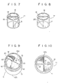
- Fig. 9 and 10 are an enlarged perspective view and an enlarged bottom view, respectively, of the mixing element 11.
- Both end faces 21 of the blade 14 opposed in the longitudinal direction of the mixing element 11 are curved in the direction of the thickness and rounded.
- a pair of corner portions 22 of each of the fluid passages 15 and 16 are rounded lest the inner peripheral surface of the passage tube 13 and the surface of the blade 14 should cross at an acute angle.
- One end face of the passage tube 13 has an inner annular projection 13a, while the other end face has an outer annular projection 13b.
- both end faces of the blade 18 of the mixing element 12 and the four corner portions of the fluid passages 19 and 20 are rounded.
- both end faces of the passage tube 17 have the same annular projections as those of the passage tube 13.
- the passage tubes 13 and 17 and their corresponding blades 14 and 18 of the mixing elements 11 and 12 are integral, no gap is formed between each blade and the inner peripheral surface of its corresponding passage tube. Moreover, the mixing elements 11 and/or 12 are coupled by fixing the passage tubes 13 and/or 17 together, so that it is unnecessary to fix the blades by welding or brazing. Therefore, fluid never stagnates at the junctions of the mixing elements. Since the blades need not be bonded to one another, it is unnecessary to flatten the end faces of the blades 14 and 18. Thus, the end faces of the blades 14 and 18 can be rounded so that the flow resistance of the fluid may be lowered. Since the corner portions of the fluid passages 15, 16, 19 and 20 are rounded, there is no dead space, and the fluid flowing through the passages is prevented from stagnating at the corner portions.
- FIG. 11 the first element 11 and the second element 12 are positioned with their blades 14 and 18 crossing at right angles.
- the inner annular projection of the passage tube 17 of the element 12 is fitted in the outer annular projection 13b of the passage of the element 11.
- the inner annular projection 13a may be fitted in the outer annular projection of the element 12.
- the second element 12 and the third element 11 are posited in the same way as the first element 11 and the second element 12, with the inner annular projection of the passage tube of the third element 11 fitted in the outer annular projection of the passage tube 17 of the second element 12.
- the inner annular projection of the passage tube 17 of the second element 12 may be fitted in the outer annular projection of the passage tube of the third element 11.
- the third element 11 and the fourth element 12 are coupled in the same manner as the first element 11 and the second element 12, and the fourth element 12 and the fifth element 11 (not shown) are coupled in the same manner as the second element 12 and the third element 11, and so forth.
- the passage tubes of all the mixing elements 11 and 12 are welded or brazed, thus forming a motionless mixer.
- they may be fitted in a cylindrical casing 23 as shown in Fig. 12, thus forming a motionless mixer 29.
- the motionless mixer 29 mixes two fluids FA and FB in the following manner.
- the fluids FA and FB rotate 90° in a helically right-handed manner as they flow through the first mixing element 11.
- the fluids FA and FB branch each into two streams at the junction of the first element 11 and the second element 12.
- One of the two streams of fluid FA thus mixes with one of the streams of fluid FB as it flows through the second element 12.
- the other stream of fluid FA mixed with the other stream of fluid FB as it flows through the second element 12.
- Two fluid mixture streams rotate 90° in helically left-handed manner as they pass through the second mixing element 12. These fluid mixture streams branch each into two sub-streams at the junction of the second element 12 and the third element 11.
- One of the sub-streams of one of the fluid mixture streams mixes with one of the sub-streams of the other fluid mixture streams.
- the other sub-stream of the first fluid mixture stream mixes with the other sub-stream of the other fluid mixture stream.
- the fluids FA and FB are further mixed as they enter and flow through the other mixing elements 11 and 12. Whenever the fluids FA and FB rotate 90°, they undergo a vortex motion and thus mixed together. As they rotate, branch and join several times while flowing through the mixing elements 11 and 12, they are thoroughly mixed to form a homogeneous fluid.
- a motionless mixer 30 shown in Fig. 14 is formed by coupling the mixing elements 11 and 12, as shown in Fig. 13.
- a mixing unit 24 is formed by coupling a pair of mixing elements 11 so that the facing end edges of their blades 14 are arranged in the same direction.
- a mixing unit 25 is formed by coupling a pair of mixing elements 12 so that the facing end edges of their blades 18 are arranged in the same direction.
- the mixing units 24 and 25 are arranged in the casing so that the facing end edges of the blades 14 and 18 are crossed at right angles.
- the fluids rotate helically right-handed at 180 degrees while they flow through the mixing unit 24. After the fluids are divided and joined at the junction of the mixing units 24 and 25, they rotate helically left-handed at 180 degrees as they flow through the mixing unit 25. Thus, in this motionless mixer 30, the fluids are mixed thoroughly after this process is repeated several times.
- a motionless mixer 31 shown in Fig. 16 is assembled by coupling the mixing elements 11 and 12 as shown in Fig. 15.
- a mixing unit 26 is formed by coupling a pair of mixing units 11 so that the facing end edges of their blades 14 cross at right angles.
- a mixing unit 27 is formed by coupling a pair of mixing elements 12 so that the facing end edges of their blades 18 cross at right angles.
- the mixing units 26 and 27 are arranged alternately in the casing 23 so that the facing end edges of the blades 14 and 18 cross at right angles at their junctions.
- the motionless mixer 31 As the fluids flow through the mixing unit 26, they rotate helically right-handed at 90 degrees, are then divided and joined, and further rotate helically right-handed at 90 degrees. The fluids are then divided and joined at the junction of the mixing units 26 and 27. Then, as the fluids flow through the mixing unit 27, they rotate helically left-handed at 90 degrees, are then divided and joined, and rotate helically left-handed at 90 degrees. Thus, the two fluids are mixed thoroughly after the rotation, division, and joining are repeated several times while they flow through the motionless mixer 31.
- the mixing elements 11 and 12 are arranged alternately in the casing 23 with cylindrical spacer members 28 interposed between them.
- the mixing elements 11 and 12 are so arranged that those facing end edges of the blades 14 and 18 which adjoin one of the spacer members 28 at each side cross at right angles.
- the fluids rotate helically right-handed at 90 degrees as they flow through the mixing element 11, and then join at the spacer members 28. Once joined, the fluids are divided by the mixing element 12, and then rotate helically left-handed at 90 degrees. Thus, the fluids are mixed thoroughly after the rotation, joining, and division are repeated several times.
- motionless mixers are easy to manufacture because their blades need not be welded or brazed to one another. In the absence of bonded portions between the blades, the fluids never stagnate. Since the motionless mixers are formed by longitudinally coupling the mixing elements, the frequency of the fluid division per unit length may readily be increased by shortening the mixing elements. In these motionless mixer, therefore, even viscous fluids can be mixed with ease.
- Fig. 18 shows a mixing element 33 in which both end edges of a blade 35 are depressed toward the center of a passage tube 34.
- the concave end edges of the blade 35 regularize the passage time of the fluids flowing through each mixing element 33, and can increase the efficiency of the mixing in the mixing element 33.
- Fig. 19 shows a mixing element 36 having three fluid passages 37, 38 and 39. This mixing element 36 can mix three fluids. When mixing two fluids only, it enjoys higher mixing efficiency.
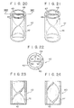
- Figs. 20 and 21 show mixing elements 40 and 41, respectively, of a 180-degree-twist type according to another embodiment of this invention.
- the mixing element 40 comprises a cylindrical passage tube 42 and a helical blade 43 therein.
- the blade 43 is twisted clockwise (right-handed) at 180 degrees, extending from one end portion of the mixing element 40 to the other along the longitudinal direction of the element 40.
- the mixing element 41 comprises a cylindrical passage tube 46 and a helical blade 47 therein.
- the blade 47 is twisted counterclockwise (left-handed) at 180 degrees, extending from one end portion of the mixing element 41 to the other along the longitudinal direction of the element 41.
- the blade 43 or 47 and its corresponding passage tube 42 or 46 respectively are formed as an integral body.
- Fluid passages 44 and 45, partitioned by the blade 43, and turned helically clockwise are formed in the passage tube 42 of the mixing element 40.
- Fluid passages 48 and 49, partitioned the blade 47 and turned helically counterclockwise are formed in the passage tube 46 of the mixing element 41.
- Those sections of the fluid passages 44, 45, 48 and 49 which are perpendicular to the flow direction are each in the form of a semicircular along the whole passage region.
- the mixing element 40 As shown in the plan view of Fig. 22, four corner portions 50 at the boundary between the blade 43 and the inner peripheral surface of the passage tube 42 are rounded. As seen from the sectional views of the mixing element 40 of Figs. 23 and 24, both end edges of the blade 43 are depressed toward the central portion of the passage tube 42. The end faces of the blade 43 are rounded. In the mixing element 41, the four corner portions of the fluid passage and the end edges of the blade are formed in the same manner as those of the mixing element 40.
- the mixing elements 40 and 42 are arranged so that the respective end edges of their blades 43 and 47 cross at right angles.
- the mixing elements 40 and 41 are fitted alternately in the casing 23.
- outer and inner annular projections may be formed on one and the other end faces, respectively, of each of the passage tubes 42 and 46.
- the mixing elements 40 and 41 may be coupled by fitting the outer annular projection of the passage tube 42 (or 46) on the inner annular projection of the passage tube 46 (or 42).
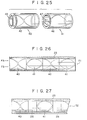
- the two fluids FA and FB rotate helically right-handed at 180 degrees as they flow through the mixing element 40.
- the fluids FA and FB are divided at the junction of the mixing elements 40 and 41, and then join their respective partner fluids FB and FA which are divided after separately flowing through the opposite fluid passages. Then, the divided and joined fluids rotate helically left-handed at 180 degrees as they flow through the mixing element 41.
- the two fluids FA and FB are mixed into a single homogeneous fluid after undergoing the 180-degree rotation, division, and joining.
- a motionless mixer 52 shown in Fig. 27 the mixing elements 40 and 41 are arranged alternately in the casing 23 with the spacer members 28 interposed between them.
- the fluids rotate helically right-handed at 180 degrees as they flow through the mixing element 40, and then join at the spacer members 28. Once joined, the fluids are divided by the mixing element 41, and then rotate helically left-handed at 180 degrees. Thus, the fluids are mixed thoroughly after the rotation, joining, and division are repeated several times.
- the 180-degree-twist type mixing element may be also provided with three fluid passages 53, 54 and 55, as shown in the plan view of Fig. 28.
- the blades 43 and 47 of the mixing elements 40 and 41 need not always be so formed that their end edges are depressed toward the central portions of the passage tubes 42 and 46, or that their end faces are curved in the direction of the thickness.
- the mixing elements 40 and 41 and the motionless mixer 51 and 52 provide the same effects as those of the mixing elements 11 and 12 and the motionless mixers 29, 30, 31 and 32.
- FIG. 29 and 30 show a mixing element casting apparatus of an injection molding type.
- a mounting plate 61 is fixedly erected on a suitable support, and a templet 62 is fixed to the mounting plate 61.
- a horizontally extending cylindrical depression 62a is formed in the side face of the templet 62 opposite to the mounting plate 61.
- a stripper plate 64 with a cylindrical hole 64a is put on the fixed templet 62 so that the hole 64a is in alignment with the depression 62a.
- a templet 63 with a cylindrical hole 63a moves toward and away from the fixed templet 62.
- the depression 62a and the holes 64a and 63a are equal in diameter.
- a bearing 65 is embedded in the templet 63 so that its inner peripheral surface is flush with that of the hole 63a.
- a core 67 for the mixing element 11 is attached to a longitudinal end portion of a cylindrical core holder 66.
- the core holder 66 is inserted in the holes 64a and 63a so that the core 67 is fitted in the depression 62a.
- the core holder 66 is rotatablly supported by the movable templet 63 with the aid of the bearing 65.
- a cavity 68 is formed between the depression 62a and the core 67, communicating with a molding nozzle 70 by means of a runner 69 in the mounting plates 61 and 62.
- the casting apparatus constructed in this way, when a fused plastic material is injected into the molding nozzle 70, it flows through the runner 69 to be fed into the cavity 68. Thereupon, the cavity 68 and a helical groove of the core 67 is filled with the fused plastic. Then, the fused plastic is cooled and solidified in the cavity 68 and the helical groove. After the fused plastic is solidified, the templet 63 is moved away from the templet 62, and a plastic molding attached to the core 67 is taken out of the depression 62a by moving the templet 63, the stripper plate 64, the core holder 66, and the core 67 away from the templet 62.
- the templet 63 is separated from the stripper plate 64 while helically rotating the core holder 66 along the groove of the core 67, the molding is stripped from the core 67. Thereafter, the portions solidified in the runner 69 are trimmed off from the molding in the runner 69, and as a result, the mixing element 11 as shown in Fig. 7 is completed.
- the mixing element 11 with the passage tube 13 and the blade 14 formed as an integral body is readily manufactured.
- the other mixing elements 12, 40 and 41 may be manufactured in a like manner.
- Fig. 31 shows a die member for casting the mixing element 12.
- the die member comprises upper, intermediate, and lower dies 71, 72 and 73 made of aluminum or cast iron.
- the upper die 71 includes a metal plate 74 and protrusions 76 and 77 projecting under the metal plate 74.
- a depression 75 in the form of a thin disk is bored in the lower surface of the metal plate 74.
- the pair of protrusions 76 and 77 in the depression 75 are so shaped as to occupy the respective halves of the fluid passages 19 and 20.
- the intermediate die 72 has a circular hole 78 bored across the thickness with a diameter substantially equal to the outside diameter of the mixing element, and a runner 78a opening into the circular hole 78.
- the lower die 73 includes a metal plate 79 and protrusions 81 and 82 projecting over the metal plate 79.
- a boss 80 in the form of a thin disk is formed on the upper surface of the metal plate 79.
- the protrusion 81 on the boss 80 is so shaped as to occupy the fluid passage 19 when its flat lateral face 81a is united with a flat lateral face 76a of the protrusion 76.
- the protrusion 82 is so shaped as to occupy the other fluid passages 20 when its flat lateral face 82a is united with a flat lateral face 77a of the protrusion 77.
- the diameters of the depression 75 and the boss 80 are substantially equal, and are a little smaller than that of the circular hole 78.
- the upper, intermediate, and lower dies 71, 72 and 73 are assembled by fitting the protrusions 76, 77, 81 and 82 in the circular hole 78 so that the lateral faces 76a and 77a of the protrusions 76 and 77 are in contact with the lateral faces 81a and 82a of the protrusions 81 and 82, respectively.
- a portion corresponding to the blade 18 is formed between the helical lateral faces of the protrusions 76 and 82 and between those of the protrusions 77 and 81.
- a portion corresponding to the passage tube 17 is formed between the circumferential faces of the protrusions 76, 77, 81 and 82 and the inner peripheral surface of the circular hole 78.
- a portion corresponding to the outer annular projection (projection 13b of Fig. 9) at the end face of the mixing element 12 is formed between the outer peripheral surface of the boss 80 and the inner peripheral surface of the circular hole 78, while a portion corresponding to the inner annular projection (projection 13b of Fig.
- the split dies shown in Fig. 31 are assembled in the aforesaid manner.
- Fused wax is injected into the cavity of the die assembly through the runner 78a.
- the injected wax is solidified to form a wax model in the shape shown in Fig. 8.
- a plurality of wax models are coupled so as to be fit for casting.
- the wax model assembly is immersed in a fire-resistant emulsion, and then covered with a sand layer by sprinkling.
- the immersion in the fire-resistant emulsion and the sand coating are repeated to form a layer of fire-resistant material on the surface of the wax model assembly.
- the wax model assembly is wholly heated to liquate the wax.
- the resultant sand mold is sintered at a high temperature.
- a molten material such as aluminum, magnetic or non-magnetic stainless steel, nickel, magnetic or non-magnetic iron, copper, or plastic, is poured into the mold.
- the sintered sand mold is broken after the poured material is solidified, the 90-degree-twist type mixing element 12 as shown in Fig. 8 is produced.
- the mixing element may be manufactured by directly injecting molten plastic into the split dies shown in Fig. 31 without using wax.
- the mixing element 11 can be manufactured in like manner.
- wax models for the 90-degree-twist type mixing elements 11 and 12 are first formed in the aforementioned manner. Then, two 90-degree-twist type wax models are longitudinally coupled and bonded together. Thus, wax models for the 180-degree-twist mixing element 40 or 41 with the shape shown in Fig. 20 or 21 is obtained.
- a sand mold is formed by the use of the wax models in the aforementioned manner, and a molten material for the mixing element such as aluminum is poured into the sand mold.
- the process for fusing the core which is needed in the conventional manufacturing method, can be omitted.
- the method requires fewer manufacturing processes, thus facilitating the manufacture and reducing the manufacturing cost.
- the end edges 21 of the blade 14 and the corner portions 22 of the fluid passages 15 and 16, as shown in Fig. 9, may be rounded with ease.
- the manufacture of the 180-degree-twist mixing element is not easy.
- the mixing element of this type can readily be manufactured by only longitudinally coupling the 90-degree-twist type wax models.
Abstract
Description
- This invention relates to a mixing element for mixing two or more fluids and a motionless mixer using the same.
- Motionless mixers (trademark: Static Mixers) have no mechanical moving parts and are so designed that fluids are mixed as they are passed through passages in a tube having a helical blade therein. The motionless mixers of this type are used in various fields, such as chemical plants, food industry, environmental pollution prevention technology, etc. In a prior art motionless mixer, as shown in Figs. 1 to 3, a plurality of
helical blades passage tube 3. Theblades passage tube 3 partitioned by theblades - Conventionally, the
helical blades helical blades cylindrical passage tube 3. Thus, the manufacture of the motionless mixer is not easy, and the fluids may often stagnate at the junctions where the adhesive agent is swollen. Owing to working errors, moreover, narrow gaps are formed between thehelical blades passage tube 3. These gaps reduce the efficiency of fluid mixing. As shown in the sectional view of Fig. 4 taken along line IV-IV of Fig. 3, the surface of theblade 1 and the inner peripheral surface of thepassage tube 3 cross at substantially right angles, so that acute-angleddead spaces 4 are formed at four corner portions of the inside regions of thepassage tube 3 partitioned by theblade 1. The fluids may stagnate at thedead spaces 4. Moreover, the flatness of an end edge la of theblade 1 increases the flow resistance. - Fig. 5 shows a motionless mixer with helically twisted fluid passage tubes. As shown in Fig. 6, the fluid passage of each of
passage tubes passage tubes passage tubes similar passage tubes 6a and 6b at right angles at the longitudinal end portions. Since it is difficult to manufacture a pair of helically twisted tubes, the manufacturing cost of this motionless mixer is high. - An object of this invention is to provide a mixing element in which a helical blade and a fluid passage tube are formed as an integral body.
- Another object of the invention is to provide a motionless mixer using mixing elements in which a helical blade and a fluid passage tube are formed as an integral body.
- Still another object of the invention is to provide a motionless mixer in which fluids are prevented from stagnating.
- A further object of the invention is to provide a motionless mixer reduced in flow resistance and in fluid pressure loss.
- A still further object of the invention is to provide a motionless mixer improved in fluid mixing efficiency.
- An additional object of the invention is to provide a motionless mixer low in manufacturing cost.
- According to this invention, there is provided a mixing element for a motionless mixer without a mechanical moving part whereby two or more fluids are mixed as the fluids flow through said motionless mixer, said mixing element comprising: a passage tube through which the fluids flow; and a helical blade formed in the passage tube so as to be integral therewith, the interior of said passage tube being partitioned by said blade to form a plurality of fluid passages.
- The fluids to be mixed by the motionless mixer of the invention include liquid, gas and particulates. According to the invention, the motionless mixer is so designed as to mix two or more fluids with different properties or ingredients. The properties may include, for example, viscosity and other physical properties, composition, temperature, color, particle size, etc. The motionless mixer can produce liquid-gas mixtures, as well as liquid-liquid mixtures and gas-gas mixtures. In some cases, the fluids may undergo a chemical reaction as they are mixed in the motionless mixer.
- This invention can be more fully understood from the following detailed description when taken in conjunction with the accompanying drawings, in which:
- Figs. 1 to 3 are schematic views showing a prior art motionless mixer;
- Fig. 4 is a sectional view taken along line IV- IV of Fig. 3;
- Fig. 5 is a schematic view of another prior art motionless mixer with helically twisted passage tubes;
- Fig. 6 is a sectional view of the motionless mixer of Fig. 5;
- Fig. 7 is a perspective view of a right-handed 90-degree-rotation type mixing element according to one embodiment of this invention;
- Fig. 8 is a perspective view of a left-handed 90-degree-rotation type mixing element according to one embodiment of this invention;
- Fig. 9 is an enlarged perspective view of the mixing element shown in Fig. 7;
- Fig. 10 is an enlarged bottom view of the mixing element of Fig. 7;
- Figs. 11 to 17 show motionless mixers according to various other embodiments of the invention, in which Figs. 11, 13 and 15 are perspective views for illustrating the way the motionless mixers are assembled by coupling the mixing elements, and Figs. 12, 14, 16 and 17 are side views showing the assembled motionless mixers;
- Fig. 18 is a sectional view of a right-handed 90-degree-rotation type mixing element according to another embodiment of the invention;
- Fig. 19 is a perspective view of a 90-degree-rotation type mixing element with three fluid passages according to still another embodiment of the invention;
- Fig. 20 is a perspective view of a right-handed 180-degree-rotation type mixing element according to a further embodiment of the invention;
- Fig. 21 is a perspective view of a left-handed 180-degree-rotation type mixing element according to an embodiment of the invention;
- Fig. 22 is a plan view of the mixing element shown in Fig. 20;
- Fig. 23 is a sectional view taken along line XXIII-XXIII of Fig. 20;
- Fig. 24 is a sectional view taken along line perpendicular to the line XXIII-XXIII of Fig. 20;
- Figs. 25 to 27 show motionless mixers according to various other embodiments of the invention, in which Fig. 25 is a perspective view for illustrating the way the motionless mixer is assembled by coupling the mixing elements, and Figs. 26 and 27 are side views showing the assembled motionless mixers;
- Fig. 28 is a plan view of a 180-degree-rotation type mixing element with three fluid passages according to an alternative embodiment of the invention;
- Figs. 29 and 30 are sectional view and a perspective view, respectively, showing a molding apparatus used for injection molding of mixing elements; and
- Fig. 31 is a disassembled perspective view showing a casting apparatus for mixing elements based on the lost wax investment casting method.
- Figs. 7 and 8
show mixing elements mixing element 11 comprises acylindrical passage tube 13 and ahelical blade 14 therein. Theblade 14 is twisted clockwise (right-handed) at 90 degrees, extending from one end portion of themixing element 11 to the other along the longitudinal direction of theelement 11. Themixing element 12 comprises acylindrical passage tube 17 and ahelical blade 18 therein. Theblade 18 is twisted counterclockwise (left-handed) at 90 degrees, extending from one end portion of themixing element 12 to the other along the longitudinal direction of theelement 12. Theblade corresponding passage tube Fluid passages blade 14 and turned helically clockwise are formed in thepassage tube 13 of themixing element 11.Fluid passages blade 18 and turned helically counterclockwise are formed in thepassage tube 17 of themixing element 12. Those sections of thefluid passages - Fig. 9 and 10 are an enlarged perspective view and an enlarged bottom view, respectively, of the
mixing element 11. Both end faces 21 of theblade 14 opposed in the longitudinal direction of themixing element 11 are curved in the direction of the thickness and rounded. A pair ofcorner portions 22 of each of thefluid passages passage tube 13 and the surface of theblade 14 should cross at an acute angle. One end face of thepassage tube 13 has an inner annular projection 13a, while the other end face has an outerannular projection 13b. Likewise, both end faces of theblade 18 of the mixingelement 12 and the four corner portions of thefluid passages passage tube 17 have the same annular projections as those of thepassage tube 13. - Since the
passage tubes corresponding blades elements elements 11 and/or 12 are coupled by fixing thepassage tubes 13 and/or 17 together, so that it is unnecessary to fix the blades by welding or brazing. Therefore, fluid never stagnates at the junctions of the mixing elements. Since the blades need not be bonded to one another, it is unnecessary to flatten the end faces of theblades blades fluid passages - A motionless mixer using the
mixing elements first element 11 and thesecond element 12 are positioned with theirblades passage tube 17 of theelement 12 is fitted in the outerannular projection 13b of the passage of theelement 11. (Alternatively, the inner annular projection 13a may be fitted in the outer annular projection of theelement 12.) Thesecond element 12 and the third element 11 (not shown) are posited in the same way as thefirst element 11 and thesecond element 12, with the inner annular projection of the passage tube of thethird element 11 fitted in the outer annular projection of thepassage tube 17 of thesecond element 12. (Alternatively, the inner annular projection of thepassage tube 17 of thesecond element 12 may be fitted in the outer annular projection of the passage tube of thethird element 11.) Thethird element 11 and the fourth element 12 (neither one shown) are coupled in the same manner as thefirst element 11 and thesecond element 12, and thefourth element 12 and the fifth element 11 (not shown) are coupled in the same manner as thesecond element 12 and thethird element 11, and so forth. The passage tubes of all the mixingelements cylindrical casing 23 as shown in Fig. 12, thus forming amotionless mixer 29. - The
motionless mixer 29 mixes two fluids FA and FB in the following manner. The fluids FA and FB rotate 90° in a helically right-handed manner as they flow through thefirst mixing element 11. The fluids FA and FB branch each into two streams at the junction of thefirst element 11 and thesecond element 12. One of the two streams of fluid FA thus mixes with one of the streams of fluid FB as it flows through thesecond element 12. Similarly, the other stream of fluid FA mixed with the other stream of fluid FB as it flows through thesecond element 12. Two fluid mixture streams rotate 90° in helically left-handed manner as they pass through thesecond mixing element 12. These fluid mixture streams branch each into two sub-streams at the junction of thesecond element 12 and thethird element 11. One of the sub-streams of one of the fluid mixture streams mixes with one of the sub-streams of the other fluid mixture streams. Likewise, the other sub-stream of the first fluid mixture stream mixes with the other sub-stream of the other fluid mixture stream. In similar manner the fluids FA and FB are further mixed as they enter and flow through theother mixing elements elements - A
motionless mixer 30 shown in Fig. 14 is formed by coupling the mixingelements unit 24 is formed by coupling a pair of mixingelements 11 so that the facing end edges of theirblades 14 are arranged in the same direction. Likewise, a mixingunit 25 is formed by coupling a pair of mixingelements 12 so that the facing end edges of theirblades 18 are arranged in the same direction. In themotionless mixer 30, the mixingunits blades - In the
motionless mixer 30, the fluids rotate helically right-handed at 180 degrees while they flow through the mixingunit 24. After the fluids are divided and joined at the junction of the mixingunits unit 25. Thus, in thismotionless mixer 30, the fluids are mixed thoroughly after this process is repeated several times. - A
motionless mixer 31 shown in Fig. 16 is assembled by coupling the mixingelements unit 26 is formed by coupling a pair of mixingunits 11 so that the facing end edges of theirblades 14 cross at right angles. Likewise, a mixingunit 27 is formed by coupling a pair of mixingelements 12 so that the facing end edges of theirblades 18 cross at right angles. In themotionless mixer 31, the mixingunits casing 23 so that the facing end edges of theblades - In the
motionless mixer 31, as the fluids flow through the mixingunit 26, they rotate helically right-handed at 90 degrees, are then divided and joined, and further rotate helically right-handed at 90 degrees. The fluids are then divided and joined at the junction of the mixingunits unit 27, they rotate helically left-handed at 90 degrees, are then divided and joined, and rotate helically left-handed at 90 degrees. Thus, the two fluids are mixed thoroughly after the rotation, division, and joining are repeated several times while they flow through themotionless mixer 31. - In a
motionless mixer 32 shown in Fig. 17, the mixingelements casing 23 withcylindrical spacer members 28 interposed between them. The mixingelements blades spacer members 28 at each side cross at right angles. - In the
motionless mixer 32, the fluids rotate helically right-handed at 90 degrees as they flow through the mixingelement 11, and then join at thespacer members 28. Once joined, the fluids are divided by the mixingelement 12, and then rotate helically left-handed at 90 degrees. Thus, the fluids are mixed thoroughly after the rotation, joining, and division are repeated several times. - These motionless mixers are easy to manufacture because their blades need not be welded or brazed to one another. In the absence of bonded portions between the blades, the fluids never stagnate. Since the motionless mixers are formed by longitudinally coupling the mixing elements, the frequency of the fluid division per unit length may readily be increased by shortening the mixing elements. In these motionless mixer, therefore, even viscous fluids can be mixed with ease.
- Fig. 18 shows a mixing
element 33 in which both end edges of ablade 35 are depressed toward the center of a passage tube 34. The concave end edges of theblade 35 regularize the passage time of the fluids flowing through each mixingelement 33, and can increase the efficiency of the mixing in the mixingelement 33. Fig. 19 shows a mixingelement 36 having threefluid passages element 36 can mix three fluids. When mixing two fluids only, it enjoys higher mixing efficiency. - Figs. 20 and 21
show mixing elements element 40 comprises acylindrical passage tube 42 and ahelical blade 43 therein. Theblade 43 is twisted clockwise (right-handed) at 180 degrees, extending from one end portion of the mixingelement 40 to the other along the longitudinal direction of theelement 40. The mixingelement 41 comprises acylindrical passage tube 46 and ahelical blade 47 therein. Theblade 47 is twisted counterclockwise (left-handed) at 180 degrees, extending from one end portion of the mixingelement 41 to the other along the longitudinal direction of theelement 41. Theblade corresponding passage tube Fluid passages blade 43, and turned helically clockwise are formed in thepassage tube 42 of the mixingelement 40.Fluid passages blade 47 and turned helically counterclockwise are formed in thepassage tube 46 of the mixingelement 41. Those sections of thefluid passages - Also in the mixing
element 40, as shown in the plan view of Fig. 22, fourcorner portions 50 at the boundary between theblade 43 and the inner peripheral surface of thepassage tube 42 are rounded. As seen from the sectional views of the mixingelement 40 of Figs. 23 and 24, both end edges of theblade 43 are depressed toward the central portion of thepassage tube 42. The end faces of theblade 43 are rounded. In the mixingelement 41, the four corner portions of the fluid passage and the end edges of the blade are formed in the same manner as those of the mixingelement 40. - There will now be described a motionless mixer using the
mixing elements elements blades motionless mixer 51 shown in Fig. 26, the mixingelements casing 23. In this case, outer and inner annular projections may be formed on one and the other end faces, respectively, of each of thepassage tubes elements motionless mixer 51 formed in this manner, the two fluids FA and FB rotate helically right-handed at 180 degrees as they flow through the mixingelement 40. The fluids FA and FB are divided at the junction of the mixingelements element 41. Thus, the two fluids FA and FB are mixed into a single homogeneous fluid after undergoing the 180-degree rotation, division, and joining. - In a
motionless mixer 52 shown in Fig. 27, the mixingelements casing 23 with thespacer members 28 interposed between them. In thismotionless mixer 52, the fluids rotate helically right-handed at 180 degrees as they flow through the mixingelement 40, and then join at thespacer members 28. Once joined, the fluids are divided by the mixingelement 41, and then rotate helically left-handed at 180 degrees. Thus, the fluids are mixed thoroughly after the rotation, joining, and division are repeated several times. - The 180-degree-twist type mixing element may be also provided with three
fluid passages blades elements passage tubes - The mixing
elements motionless mixer elements motionless mixers - There will now be described a method and an apparatus for manufacturing the mixing element according to this invention. Fig. 29 and 30 show a mixing element casting apparatus of an injection molding type. In Fig. 29, a mounting
plate 61 is fixedly erected on a suitable support, and atemplet 62 is fixed to the mountingplate 61. A horizontally extending cylindrical depression 62a is formed in the side face of thetemplet 62 opposite to the mountingplate 61. Astripper plate 64 with a cylindrical hole 64a is put on the fixedtemplet 62 so that the hole 64a is in alignment with the depression 62a. Atemplet 63 with acylindrical hole 63a moves toward and away from the fixedtemplet 62. The depression 62a and theholes 64a and 63a are equal in diameter. Abearing 65 is embedded in thetemplet 63 so that its inner peripheral surface is flush with that of thehole 63a. Acore 67 for the mixingelement 11 is attached to a longitudinal end portion of acylindrical core holder 66. Thecore holder 66 is inserted in theholes 64a and 63a so that thecore 67 is fitted in the depression 62a. Thecore holder 66 is rotatablly supported by themovable templet 63 with the aid of thebearing 65. Acavity 68 is formed between the depression 62a and thecore 67, communicating with amolding nozzle 70 by means of arunner 69 in the mountingplates - According to the casting apparatus constructed in this way, when a fused plastic material is injected into the
molding nozzle 70, it flows through therunner 69 to be fed into thecavity 68. Thereupon, thecavity 68 and a helical groove of thecore 67 is filled with the fused plastic. Then, the fused plastic is cooled and solidified in thecavity 68 and the helical groove. After the fused plastic is solidified, thetemplet 63 is moved away from thetemplet 62, and a plastic molding attached to thecore 67 is taken out of the depression 62a by moving thetemplet 63, thestripper plate 64, thecore holder 66, and the core 67 away from thetemplet 62. Then, when thetemplet 63 is separated from thestripper plate 64 while helically rotating thecore holder 66 along the groove of the core 67, the molding is stripped from thecore 67. Thereafter, the portions solidified in therunner 69 are trimmed off from the molding in therunner 69, and as a result, the mixingelement 11 as shown in Fig. 7 is completed. Thus, the mixingelement 11 with thepassage tube 13 and theblade 14 formed as an integral body is readily manufactured. Theother mixing elements - There will now be described a method and an apparatus for manufacturing the mixing element on the basis of the lost wax investment casting method. Fig. 31 shows a die member for casting the mixing
element 12. The die member comprises upper, intermediate, and lower dies 71, 72 and 73 made of aluminum or cast iron. Theupper die 71 includes ametal plate 74 andprotrusions metal plate 74. Adepression 75 in the form of a thin disk is bored in the lower surface of themetal plate 74. The pair ofprotrusions depression 75 are so shaped as to occupy the respective halves of thefluid passages circular hole 78 bored across the thickness with a diameter substantially equal to the outside diameter of the mixing element, and a runner 78a opening into thecircular hole 78. Thelower die 73 includes ametal plate 79 andprotrusions metal plate 79. Aboss 80 in the form of a thin disk is formed on the upper surface of themetal plate 79. Theprotrusion 81 on theboss 80 is so shaped as to occupy thefluid passage 19 when its flat lateral face 81a is united with a flat lateral face 76a of theprotrusion 76. Likewise, theprotrusion 82 is so shaped as to occupy the otherfluid passages 20 when its flat lateral face 82a is united with a flat lateral face 77a of theprotrusion 77. The diameters of thedepression 75 and theboss 80 are substantially equal, and are a little smaller than that of thecircular hole 78. The upper, intermediate, and lower dies 71, 72 and 73 are assembled by fitting theprotrusions circular hole 78 so that the lateral faces 76a and 77a of theprotrusions protrusions blade 18 is formed between the helical lateral faces of theprotrusions protrusions passage tube 17 is formed between the circumferential faces of theprotrusions circular hole 78. Also, a portion corresponding to the outer annular projection (projection 13b of Fig. 9) at the end face of the mixingelement 12 is formed between the outer peripheral surface of theboss 80 and the inner peripheral surface of thecircular hole 78, while a portion corresponding to the inner annular projection (projection 13b of Fig. 9) is formed between the inner peripheral surface of thedepression 75 and the circumferential faces of theprotrusions - There will now be described the method of manufacturing the mixing element of the invention on the basis of the lost wax investment casting method using the aforementioned split dies. First, the split dies shown in Fig. 31 are assembled in the aforesaid manner. Fused wax is injected into the cavity of the die assembly through the runner 78a. The injected wax is solidified to form a wax model in the shape shown in Fig. 8. A plurality of wax models are coupled so as to be fit for casting. The wax model assembly is immersed in a fire-resistant emulsion, and then covered with a sand layer by sprinkling. The immersion in the fire-resistant emulsion and the sand coating are repeated to form a layer of fire-resistant material on the surface of the wax model assembly. Then the wax model assembly is wholly heated to liquate the wax. The resultant sand mold is sintered at a high temperature. Thus, a mold having a space which corresponds to that of the mixing element is manufactured. A molten material, such as aluminum, magnetic or non-magnetic stainless steel, nickel, magnetic or non-magnetic iron, copper, or plastic, is poured into the mold. When the sintered sand mold is broken after the poured material is solidified, the 90-degree-twist
type mixing element 12 as shown in Fig. 8 is produced. If the material of the mixing element is platic, the mixing element may be manufactured by directly injecting molten plastic into the split dies shown in Fig. 31 without using wax. The mixingelement 11 can be manufactured in like manner. - In the manufacture of the 180-degree-twist
type mixing elements type mixing elements twist mixing element - Thus, in the manufacture of the mixing element by the lost wax investment casting method using the split dies 71, 72 and 73, the process for fusing the core, which is needed in the conventional manufacturing method, can be omitted. Namely, the method requires fewer manufacturing processes, thus facilitating the manufacture and reducing the manufacturing cost.' Moreover, the end edges 21 of the
blade 14 and thecorner portions 22 of thefluid passages
Claims (24)
Applications Claiming Priority (4)
| Application Number | Priority Date | Filing Date | Title |
|---|---|---|---|
| JP4023/82 | 1982-01-16 | ||
| JP57004023A JPS58122831A (en) | 1982-01-16 | 1982-01-16 | Manufacture of plastic element |
| JP57009596A JPS58128134A (en) | 1982-01-26 | 1982-01-26 | Fluid mixer |
| JP9596/82 | 1982-01-26 |
Publications (3)
| Publication Number | Publication Date |
|---|---|
| EP0084180A2 true EP0084180A2 (en) | 1983-07-27 |
| EP0084180A3 EP0084180A3 (en) | 1984-04-25 |
| EP0084180B1 EP0084180B1 (en) | 1986-09-03 |
Family
ID=26337721
Family Applications (1)
| Application Number | Title | Priority Date | Filing Date |
|---|---|---|---|
| EP82112101A Expired EP0084180B1 (en) | 1982-01-16 | 1982-12-29 | Mixing element and motionless mixer |
Country Status (2)
| Country | Link |
|---|---|
| EP (1) | EP0084180B1 (en) |
| DE (1) | DE3273078D1 (en) |
Cited By (10)
| Publication number | Priority date | Publication date | Assignee | Title |
|---|---|---|---|---|
| EP0145134A2 (en) * | 1983-12-08 | 1985-06-19 | Sealed Power Corporation | Linear in-line mixing system |
| EP0214860A2 (en) * | 1985-09-06 | 1987-03-18 | Hoel Rasmusen International Inc. | Acceleration valve and motionless mixer |
| US4884894A (en) * | 1985-08-14 | 1989-12-05 | Yuugenkaisha Ohnobankinkougyousho | Fluid mixing element |
| GB2271725A (en) * | 1991-05-20 | 1994-04-27 | Zhi Qiang Xie | Mechanical oil/water emulsifier |
| EP0678329A1 (en) * | 1994-04-19 | 1995-10-25 | Hisao Kojima | Mixing element and method of producing the same |
| EP1149626A1 (en) * | 2000-04-27 | 2001-10-31 | Sika AG, vorm. Kaspar Winkler & Co. | Static mixing element, segment of a mixing element, static mixer and mixing blade and use thereof |
| WO2002032561A2 (en) * | 2000-10-19 | 2002-04-25 | Krauss-Maffei Kunststofftechnik Gmbh | Static mixing device for homogenising polymer melts |
| WO2010099920A2 (en) | 2009-03-02 | 2010-09-10 | Sms Siemag Ag | Energy recovery in hot strip mills by converting the cooling heat of the continuous casting plant and the residual heat of slabs and coils into electrical energy or otherwise utilizing the captured process heat |
| CH713229A1 (en) * | 2016-12-14 | 2018-06-15 | Streiff Felix | Mixing elements with high strength and mixing effect. |
| CN114749082A (en) * | 2022-05-06 | 2022-07-15 | 潍坊科技学院 | Static mixer is used in silicone adhesive production |
Citations (3)
| Publication number | Priority date | Publication date | Assignee | Title |
|---|---|---|---|---|
| DE2262016A1 (en) * | 1972-12-19 | 1974-06-20 | Mono Pumps Ltd | Flow mixer tube with serial helical divider strips - with adjacent strips of opposite hand and defining constant total flow area |
| FR2355556A1 (en) * | 1976-02-20 | 1978-01-20 | Vlieger Jean Pierre De | Static mixer for paints and plastic products - made of several identical elements screwed together having channels and mixing chambers |
| DE7733456U1 (en) * | 1977-10-29 | 1978-05-11 | Augustin, Wilfried, 2057 Reinbek | STATIC MIXER |
-
1982
- 1982-12-29 EP EP82112101A patent/EP0084180B1/en not_active Expired
- 1982-12-29 DE DE8282112101T patent/DE3273078D1/en not_active Expired
Patent Citations (3)
| Publication number | Priority date | Publication date | Assignee | Title |
|---|---|---|---|---|
| DE2262016A1 (en) * | 1972-12-19 | 1974-06-20 | Mono Pumps Ltd | Flow mixer tube with serial helical divider strips - with adjacent strips of opposite hand and defining constant total flow area |
| FR2355556A1 (en) * | 1976-02-20 | 1978-01-20 | Vlieger Jean Pierre De | Static mixer for paints and plastic products - made of several identical elements screwed together having channels and mixing chambers |
| DE7733456U1 (en) * | 1977-10-29 | 1978-05-11 | Augustin, Wilfried, 2057 Reinbek | STATIC MIXER |
Non-Patent Citations (1)
| Title |
|---|
| Bulletin KMOD-40 from Kenics Corporation, 1973 * |
Cited By (17)
| Publication number | Priority date | Publication date | Assignee | Title |
|---|---|---|---|---|
| EP0145134A3 (en) * | 1983-12-08 | 1986-12-30 | Sealed Power Corporation | Linear in-line mixing system |
| EP0145134A2 (en) * | 1983-12-08 | 1985-06-19 | Sealed Power Corporation | Linear in-line mixing system |
| US4884894A (en) * | 1985-08-14 | 1989-12-05 | Yuugenkaisha Ohnobankinkougyousho | Fluid mixing element |
| EP0214860A2 (en) * | 1985-09-06 | 1987-03-18 | Hoel Rasmusen International Inc. | Acceleration valve and motionless mixer |
| EP0214860A3 (en) * | 1985-09-06 | 1988-07-20 | Hans Christian Rasmusen | Acceleration valve and motionless mixer |
| GB2271725B (en) * | 1991-05-20 | 1996-07-03 | Zhi Qiang Xie | Mechanical oil/water emulsifier |
| GB2271725A (en) * | 1991-05-20 | 1994-04-27 | Zhi Qiang Xie | Mechanical oil/water emulsifier |
| WO1994009892A1 (en) * | 1991-05-20 | 1994-05-11 | Liu Erh | Mechanical oil/water emulsifier |
| US5399015A (en) * | 1991-05-20 | 1995-03-21 | Zhi-Qiang; Xie | Abrupt-reversal helical water-in-oil emulsification system |
| EP0678329A1 (en) * | 1994-04-19 | 1995-10-25 | Hisao Kojima | Mixing element and method of producing the same |
| EP1149626A1 (en) * | 2000-04-27 | 2001-10-31 | Sika AG, vorm. Kaspar Winkler & Co. | Static mixing element, segment of a mixing element, static mixer and mixing blade and use thereof |
| US6585407B2 (en) | 2000-04-27 | 2003-07-01 | Sika Schweiz Ag | Static mixing element, single stage static mixing element segment, static mixer, mixing vanes element and method for mixing very viscous polyurethane with a curing accelerating agent |
| WO2002032561A2 (en) * | 2000-10-19 | 2002-04-25 | Krauss-Maffei Kunststofftechnik Gmbh | Static mixing device for homogenising polymer melts |
| WO2002032561A3 (en) * | 2000-10-19 | 2003-01-03 | Krauss Maffei Kunststofftech | Static mixing device for homogenising polymer melts |
| WO2010099920A2 (en) | 2009-03-02 | 2010-09-10 | Sms Siemag Ag | Energy recovery in hot strip mills by converting the cooling heat of the continuous casting plant and the residual heat of slabs and coils into electrical energy or otherwise utilizing the captured process heat |
| CH713229A1 (en) * | 2016-12-14 | 2018-06-15 | Streiff Felix | Mixing elements with high strength and mixing effect. |
| CN114749082A (en) * | 2022-05-06 | 2022-07-15 | 潍坊科技学院 | Static mixer is used in silicone adhesive production |
Also Published As
| Publication number | Publication date |
|---|---|
| EP0084180B1 (en) | 1986-09-03 |
| DE3273078D1 (en) | 1986-10-09 |
| EP0084180A3 (en) | 1984-04-25 |
Similar Documents
| Publication | Publication Date | Title |
|---|---|---|
| US4466741A (en) | Mixing element and motionless mixer | |
| US5520460A (en) | Static mixing element | |
| US8360630B2 (en) | Mixing element for a static mixer and process for producing such a mixing element | |
| EP0084180A2 (en) | Mixing element and motionless mixer | |
| KR100518060B1 (en) | Micromixer | |
| JPS62144738A (en) | Liquid mixer | |
| FI90730C (en) | Apparatus for the preparation of putty and the like | |
| RU2091146C1 (en) | Apparatus for homogenizing high-viscosity media | |
| EP0212290B1 (en) | Fluid mixing element | |
| US4195396A (en) | Method of forming an airfoil with inner and outer shroud sections | |
| JPH07784A (en) | Mixer | |
| JP2001246234A (en) | Static mixer | |
| JP2009506912A5 (en) | ||
| JP2667659B2 (en) | Mixing element | |
| JP2000135424A (en) | Hydrostatic mixer | |
| JP2566234B2 (en) | Equipment for manufacturing mixing elements | |
| US6457855B1 (en) | Micro mixer | |
| JPS6055174B2 (en) | Mixing element manufacturing equipment | |
| JPS58128134A (en) | Fluid mixer | |
| CN108525596B (en) | Lobe cutting fluid multicomponent on-line mixing mechanism | |
| JPS62269734A (en) | Plastic element | |
| CN215917350U (en) | Microchannel detachable reducing mixing core | |
| CN216230466U (en) | Static mixer and injection molding machine with same | |
| JPH0360727A (en) | Static fluid mixer and its production | |
| CN217288355U (en) | Decomposable flat block mixing core |
Legal Events
| Date | Code | Title | Description |
|---|---|---|---|
| PUAI | Public reference made under article 153(3) epc to a published international application that has entered the european phase |
Free format text: ORIGINAL CODE: 0009012 |
|
| 17P | Request for examination filed |
Effective date: 19821229 |
|
| AK | Designated contracting states |
Designated state(s): CH DE FR GB IT LI |
|
| PUAL | Search report despatched |
Free format text: ORIGINAL CODE: 0009013 |
|
| AK | Designated contracting states |
Designated state(s): CH DE FR GB IT LI |
|
| GRAA | (expected) grant |
Free format text: ORIGINAL CODE: 0009210 |
|
| ITF | It: translation for a ep patent filed |
Owner name: BUGNION S.P.A. |
|
| AK | Designated contracting states |
Kind code of ref document: B1 Designated state(s): CH DE FR GB IT LI |
|
| REF | Corresponds to: |
Ref document number: 3273078 Country of ref document: DE Date of ref document: 19861009 |
|
| ET | Fr: translation filed | ||
| RAP2 | Party data changed (patent owner data changed or rights of a patent transferred) |
Owner name: KOJIMA, HISAO |
|
| PLBE | No opposition filed within time limit |
Free format text: ORIGINAL CODE: 0009261 |
|
| STAA | Information on the status of an ep patent application or granted ep patent |
Free format text: STATUS: NO OPPOSITION FILED WITHIN TIME LIMIT |
|
| 26N | No opposition filed | ||
| ITTA | It: last paid annual fee | ||
| PGFP | Annual fee paid to national office [announced via postgrant information from national office to epo] |
Ref country code: FR Payment date: 19921119 Year of fee payment: 11 |
|
| PGFP | Annual fee paid to national office [announced via postgrant information from national office to epo] |
Ref country code: CH Payment date: 19921123 Year of fee payment: 11 |
|
| PGFP | Annual fee paid to national office [announced via postgrant information from national office to epo] |
Ref country code: GB Payment date: 19921221 Year of fee payment: 11 |
|
| PG25 | Lapsed in a contracting state [announced via postgrant information from national office to epo] |
Ref country code: GB Effective date: 19931229 |
|
| PG25 | Lapsed in a contracting state [announced via postgrant information from national office to epo] |
Ref country code: LI Effective date: 19931231 Ref country code: CH Effective date: 19931231 |
|
| GBPC | Gb: european patent ceased through non-payment of renewal fee |
Effective date: 19931229 |
|
| PG25 | Lapsed in a contracting state [announced via postgrant information from national office to epo] |
Ref country code: FR Effective date: 19940831 |
|
| REG | Reference to a national code |
Ref country code: CH Ref legal event code: PL |
|
| REG | Reference to a national code |
Ref country code: FR Ref legal event code: ST |
|
| PGFP | Annual fee paid to national office [announced via postgrant information from national office to epo] |
Ref country code: DE Payment date: 19991228 Year of fee payment: 18 |
|
| PG25 | Lapsed in a contracting state [announced via postgrant information from national office to epo] |
Ref country code: DE Free format text: LAPSE BECAUSE OF NON-PAYMENT OF DUE FEES Effective date: 20011002 |