EP0083162B1 - Optisches Luftdaten Mess-System - Google Patents
Optisches Luftdaten Mess-System Download PDFInfo
- Publication number
- EP0083162B1 EP0083162B1 EP82306478A EP82306478A EP0083162B1 EP 0083162 B1 EP0083162 B1 EP 0083162B1 EP 82306478 A EP82306478 A EP 82306478A EP 82306478 A EP82306478 A EP 82306478A EP 0083162 B1 EP0083162 B1 EP 0083162B1
- Authority
- EP
- European Patent Office
- Prior art keywords
- radiation
- velocity
- sets
- beams
- detection volume
- Prior art date
- Legal status (The legal status is an assumption and is not a legal conclusion. Google has not performed a legal analysis and makes no representation as to the accuracy of the status listed.)
- Expired
Links
- 230000003287 optical effect Effects 0.000 title claims description 32
- 238000005259 measurement Methods 0.000 title description 19
- 230000005855 radiation Effects 0.000 claims description 98
- 238000001514 detection method Methods 0.000 claims description 31
- 239000002245 particle Substances 0.000 claims description 30
- 239000013598 vector Substances 0.000 claims description 21
- 239000000443 aerosol Substances 0.000 claims description 18
- 230000005484 gravity Effects 0.000 claims description 2
- 238000000034 method Methods 0.000 description 15
- 230000003595 spectral effect Effects 0.000 description 7
- 230000001427 coherent effect Effects 0.000 description 6
- 230000000694 effects Effects 0.000 description 6
- 238000010586 diagram Methods 0.000 description 5
- 230000008569 process Effects 0.000 description 5
- 239000012530 fluid Substances 0.000 description 4
- IJGRMHOSHXDMSA-UHFFFAOYSA-N Atomic nitrogen Chemical compound N#N IJGRMHOSHXDMSA-UHFFFAOYSA-N 0.000 description 3
- 238000010276 construction Methods 0.000 description 3
- 239000007789 gas Substances 0.000 description 3
- 230000001939 inductive effect Effects 0.000 description 3
- 230000003068 static effect Effects 0.000 description 3
- 230000001133 acceleration Effects 0.000 description 2
- 230000008901 benefit Effects 0.000 description 2
- 239000002131 composite material Substances 0.000 description 2
- 230000006835 compression Effects 0.000 description 2
- 238000007906 compression Methods 0.000 description 2
- 239000000428 dust Substances 0.000 description 2
- 238000012423 maintenance Methods 0.000 description 2
- 230000007246 mechanism Effects 0.000 description 2
- 230000037361 pathway Effects 0.000 description 2
- 238000006303 photolysis reaction Methods 0.000 description 2
- 238000012545 processing Methods 0.000 description 2
- 230000004044 response Effects 0.000 description 2
- 230000035939 shock Effects 0.000 description 2
- 238000001228 spectrum Methods 0.000 description 2
- 230000003044 adaptive effect Effects 0.000 description 1
- 230000002411 adverse Effects 0.000 description 1
- 239000005427 atmospheric aerosol Substances 0.000 description 1
- 230000015572 biosynthetic process Effects 0.000 description 1
- 230000008859 change Effects 0.000 description 1
- 238000006243 chemical reaction Methods 0.000 description 1
- 238000004140 cleaning Methods 0.000 description 1
- 239000003086 colorant Substances 0.000 description 1
- 239000012141 concentrate Substances 0.000 description 1
- 230000001143 conditioned effect Effects 0.000 description 1
- 230000003750 conditioning effect Effects 0.000 description 1
- 230000001186 cumulative effect Effects 0.000 description 1
- 230000009849 deactivation Effects 0.000 description 1
- 230000001419 dependent effect Effects 0.000 description 1
- 238000013461 design Methods 0.000 description 1
- 238000006073 displacement reaction Methods 0.000 description 1
- 230000005670 electromagnetic radiation Effects 0.000 description 1
- 239000000284 extract Substances 0.000 description 1
- 230000006872 improvement Effects 0.000 description 1
- 230000010354 integration Effects 0.000 description 1
- 230000010287 polarization Effects 0.000 description 1
- 238000010791 quenching Methods 0.000 description 1
- 230000000171 quenching effect Effects 0.000 description 1
- 230000035945 sensitivity Effects 0.000 description 1
- 230000009885 systemic effect Effects 0.000 description 1
- 239000012780 transparent material Substances 0.000 description 1
Images


Classifications
-
- G—PHYSICS
- G01—MEASURING; TESTING
- G01N—INVESTIGATING OR ANALYSING MATERIALS BY DETERMINING THEIR CHEMICAL OR PHYSICAL PROPERTIES
- G01N21/00—Investigating or analysing materials by the use of optical means, i.e. using sub-millimetre waves, infrared, visible or ultraviolet light
- G01N21/62—Systems in which the material investigated is excited whereby it emits light or causes a change in wavelength of the incident light
- G01N21/63—Systems in which the material investigated is excited whereby it emits light or causes a change in wavelength of the incident light optically excited
- G01N21/64—Fluorescence; Phosphorescence
- G01N21/6402—Atomic fluorescence; Laser induced fluorescence
-
- G—PHYSICS
- G01—MEASURING; TESTING
- G01P—MEASURING LINEAR OR ANGULAR SPEED, ACCELERATION, DECELERATION, OR SHOCK; INDICATING PRESENCE, ABSENCE, OR DIRECTION, OF MOVEMENT
- G01P5/00—Measuring speed of fluids, e.g. of air stream; Measuring speed of bodies relative to fluids, e.g. of ship, of aircraft
- G01P5/26—Measuring speed of fluids, e.g. of air stream; Measuring speed of bodies relative to fluids, e.g. of ship, of aircraft by measuring the direct influence of the streaming fluid on the properties of a detecting optical wave
-
- G—PHYSICS
- G06—COMPUTING; CALCULATING OR COUNTING
- G06F—ELECTRIC DIGITAL DATA PROCESSING
- G06F9/00—Arrangements for program control, e.g. control units
- G06F9/06—Arrangements for program control, e.g. control units using stored programs, i.e. using an internal store of processing equipment to receive or retain programs
- G06F9/30—Arrangements for executing machine instructions, e.g. instruction decode
- G06F9/38—Concurrent instruction execution, e.g. pipeline, look ahead
- G06F9/3836—Instruction issuing, e.g. dynamic instruction scheduling or out of order instruction execution
- G06F9/3842—Speculative instruction execution
-
- G—PHYSICS
- G01—MEASURING; TESTING
- G01N—INVESTIGATING OR ANALYSING MATERIALS BY DETERMINING THEIR CHEMICAL OR PHYSICAL PROPERTIES
- G01N21/00—Investigating or analysing materials by the use of optical means, i.e. using sub-millimetre waves, infrared, visible or ultraviolet light
- G01N21/17—Systems in which incident light is modified in accordance with the properties of the material investigated
- G01N2021/1793—Remote sensing
Definitions
- the invention relates to an apparatus for measuring the velocity of a moving body.
- the atmosphere contains many naturally occurring aerosols having a diameter on the order of from 0.1 to 10 micrometers.
- aerosols are pollen and dust that naturally occur in the atmosphere. These aerosols tends to follow the motion of the atmosphere in which they are entrained and hence by observing the motion of such particles, it is possible to measure the velocity of the surrounding airstream.
- optical techniques have also been utilized to measure wind.
- One such technique employed scattered sunlight as a source and cross-correlated the outputs of two radiometers having intersecting fields of view. Against localized flumes, such as the flume from a smokestack, it produced satisfactory results.
- a more sophisticated type of optical device measure the Doppler shift in light scattered by particles within the moving fluid to measure velocity along the system's optical axis.
- fringe laser velocimeter which measured a velocity component transverse to the instrument's line of sight by detecting the movement of aerosol particles through a layered pattern of interference fringes created by two intersecting beams of coherent laser light.
- US-A-4148585 describes velocimeter for measuring the three-dimensional velocity of a fluid by measuring the velocity of particles carried thereby.
- the apparatus described comprises first means (a laser) emitting radiation: second means (comprising lenses) for projecting the radiation onto a detection volume through which the fluid flows and for producing in the detection volume three sets of non-orthogonal, but linearly independent, three-dimensional patterns of radiation, each of the sets having a normal vector which has a significant component in the direction of the main axis of the apparatus as well as a transverse component at right angles thereto; third means (a lens) for focussing radiation scattered by the particles as it passes through the detection volume onto a detection area; fourth means (a photomultiplier) disposed to measure the intensity of the scattered radiation; and further means (not described in detail) responsive to the output of the fourth means for calculating the velocity of the particles relative to the apparatus.
- US-A-4148585 uses forward scattering and is designed for use in a situation where the apparatus is stationary and the fluid carrying the particles is moving. It is therefore unsuitable for use in measuring the air speed of a moving body such as an aircraft. Furthermore, the three sets of patterns of radiation cannot be generated simultaneously, and it is necessary to change a mask in order to complete the generation of all three sets. Although reference is made therein to the possibility of measuring all three components of velocity simultaneously using two diffraction gratings, no further details are given.
- EP-A-009533 describes a velocimeter which is intended to measure the air speed of an aircraft. However, this is of a fundamentally different type in that it does not use three-dimensional patterns of radiation. Instead it relies on the frequency shift in the radiation backscattered when a laser beam is incident on a moving particle. A comparison is made electronically between the frequency of electrical signals representing the backscattered radiation and the incident radiation respectively.
- Another optical technique relied upon variations in refractive index moving with the wind across the line of sight of the instrument, detecting such variation by means of a so-called double-ended system having separated source and receiver.
- an apparatus for measuring the three-dimensional velocity of a remotely located object comprising: first means emitting radiation; second means associated with said first means for projecting said radiation onto a detection volume physically separated in space from said apparatus for producing simultaneously in said detection volume three sets of non-orthogonal, but linearly independent, three-dimensional patterns of radiation, each of said sets having its own distinguishing characteristic and each of said sets having a normal vector which has a significant component in the direction of the main axis of the apparatus as well as a transverse component at right angles thereto; third means associated with said second means for focussing radiation backscattered by said object as it passes through said detection volume onto a detection area contained within said apparatus; fourth means disposed to measure the intensity of said scattered radiation; fifth means responsive to the output of said fourth means and capable of utilizing said distinguishable characteristic for identifying three separate components of said scattered radiation associated respectively with each of said three sets of radiation patterns; and sixth means responsive to the output of said fifth means for calculating the velocity of said object relative to said apparatus, at least said
- the invention provides an apparatus by means of which air data measurements that are critical to the operation of an aircraft (such as true air speed, side slip and angle of attack) can be simply and reliably measured by means of an accurate and reliable measurement device free of any Pitot tubes, pressure ports or protrusions into the airstream. Such measurements can be made at a sample location at a sufficient distance from the aircraft or any physical attachments thereto that the measurement will not be subject to systemic errors of a sort that cannot always be fully compensated for such as those caused by air compression effects and airflow disturbances.
- a divisional application has been published under Publication No. 0 227 911 on 08.07.87.
- the velocimeter described above is combined with an apparatus for inducing fluorescence in selected air molecules and thereby determining air density related parameters, for example air pressure or barometric altitude.
- the combined system contains a laser or other suitable radiation source (or sources) as well as an optical arrangement for transmitting the radiation from the laser to a sample volume in order both to form linearly independent sets of radiation fringes at the sample location as well as to focus the radiation at the sample location so as to cause selected air molecules to fluoresce.
- the device also contains an optical receiving arrangement for focusing backscattered radiation and fluorescent emissions from the sample volume onto one or more photodetectors.
- the radiation that forms the pattern of fringes originates from a single laser having an output spectral content that results not only in a significant portion of the radiation being backscattered by the type of aerosol particles that will normally be encountered at the opertional altitudes of the aircraft but which will also result in substantial fluorescence of particular molecules which comprise a known percentage of the earth's atmosphere of which Nitrogen (N 2 ) is the most prevalent.
- both radiation sources are provided and the spectral content of the radiation used to create the fringe patterns is different from that used to fluoresce the air molecules.
- both sources of radiation may be caused to propagate along a common optical path leading to the same sample volume in the external free airstream, thus permitting common receiving optical elements to function as part of both subsystems.
- the resultant backscattered radiation containing the velocity information may differ in spectral content from the fluorescent emissions containing the density (pressure) information.
- two separate photodetectors may be each provided with a suitable optical filter such that the output of one photodetector is indicative of the present intensity of the fluorescence of the selected air molecules (and thus of air pressure and density) and the output of the other photodetector is indicative of the changing intensity of the backscattered radiation caused by the movement of aerosol particles relative to the sample volume (and thus of air speed, etc.).
- a radiation source such as a Q-switched laser
- a single photodetector that is responsive both to backscattered radiation and to fluorescent re-emissions, since the backscattered radiation will cease as soon as the radiation is turned off, but the fluorescent emissions will decay exponentially.
- FIG. 1 reflects an exemplary embodiment of the present invention installed aboard a supersonic aircraft (10).
- a sample volume (12) is defined by the intersection of the laser beams (14) at the focal point of the transmitting optical subsystem, and is located at some distance removed from the nearest surface (16) of the aircraft (10) such that the sample volume (12) is in fact located in a portion of the airstream undisturbed by the supersonic shock wave (18).
- Fig. 1 it will also be seen that ouptut of the receiving optical subsystem (20) is preferably conditioned by a data processor (22) prior to display by the instrumentation system (24) and utilization by the aircraft's avionics (26).
- the data processor (22) also has, as another input, a temperature signal provided by a conventional temperature sensing subsystem (28). (A value for temperature is required to derive the pressure of a gas from its density).
- the system in effect uses changes in induced fluorescence to measure optically the density of the air mass and changes in the backscattered radiation as the scattering particle moves relative to interference fringes to measure optically the velocity of the air.
- Air density (D) combined with static temperature (T s ) can be used to determine pressure altitude (P S ): where R is the ideal gas constant.
- Static temperature (T s ) is related to total temperature (T t ) and Mach number (M) as follows:
- the fluorescent light intensity decays exponentially, and if the intensity is measured at two different times, t, and t 2 , the decay is expressed by: where L is the mean fluorescence lifetime, and is related to the mean molecular collision time and hence to the density of the gas.
- Fig. 2 illustrates graphically such an exponential relationship between Intensity (I) and Time (t) in which it can be seen that at equally spaced intervals of time (e.g., "(t 1 -t 2 )" following the interruption of the energy source at time to, the intensity is successively reduced by a constant factor.
- the collision rate constant is merely the mean collision rate between the excited molecule and all other molecules present.
- n M , n A are the number densities of species M and A respectively
- d MA is the average diameter of molecules M and A
- k is the Boltzmann constant
- T the absolute temperature
- m * MA is the reduced mass of molecules M and A
- the mean fluorescence lifetime can be determined and the density can then be computed from the relation between mean lifetime and the collision rate calculated above.
- the above-described technique has several advantages, including sensitivity to even short- lived fluorescence at low altitudes (high density, pressure), and freedom from calibration of the photodetector for absolute intensity measurement, since only relative intensity is used.
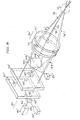
- a first embodiment of the optical subsystem (20) of the present invention comprises a high intensity light source (32) of coherent monofrequency radiation (e.g., a primary light beam (34) produced by a laser operated in single-line mode), a beam splitting device (36) for generating a first plurality of radiation beams, a modulating device (38) for generating from said first plurality of beams a second plurality of beams each having a distinguishing characteristic, a focussing device in the form of a transmit/receive window lens (40) for forming three separately identifiable three sets of non-orthogonal, but linearly independent, three-dimensional patterns of fringe planes, and a detector device (42).
- a high intensity light source of coherent monofrequency radiation
- a beam splitting device for generating a first plurality of radiation beams
- a modulating device (38) for generating from said first plurality of beams a second plurality of beams each having a distinguishing characteristic
- the secondary beams (44, 46, 48) are thus of substantially equal intensity and are arranged more or less parallel to one another and spaced at approximately equal angular intervals about, and at approximately equal radial distances from, a central axis (50).
- the secondary beams (44,46,48) impinge on a modulating array of acousto-optic cells (38) at so-called "Bragg angles" B determined in accordance with the equation where ⁇ is the wavelength of the entry beam and S is the wavelength of the acoustic waves within the cell.
- ⁇ is the wavelength of the entry beam
- S is the wavelength of the acoustic waves within the cell.
- the acoustic waves in the deflection medium inside each of the cells effectively set up a phase diffraction grating moving with the velocity of sound within the medium and having a grating spacing equal to the sound wavelength. Since the incoming beam enters the cell at the Bragg angle, a substantial percentage of the beam is diffracted from the exit side of the cell in a first order diffracted beam that is deflected from the incident light beam by an angle -2 B. This deflected beam is subjected to a slight frequency displacement ⁇ f as a result of a Doppler effect occasioned by the movement relative to the moving acoustic wave front; the deflected beam is also phase modulated in accordance with the frequency and amplitude of the sound wave.
- each pair having a substantially unshifted beam (58, 60, 62) (i.e., a zero order diffraction) and a modulated beam (52, 54, 56) (the above-mentioned deflected beams).
- the plane containing the two diverging beams (56, 62) of third beam pair (68) is oriented vertically (i.e., in the X-Z plane).
- the planes containing the first pair of beams (52, 58) and the second pair of beams (54, 60) subtend angles of -120° and +120°, respectively, with respect to the vertical (X-Y) plane..
- the window lens (40) as shown in the particular embodiment of Fig. 3 comprises a front lens element (70) and a rear lens element (72); the output beam (14) comprises a first converging beam pair (74), a second converging beam pair (76) and a third converging beam pair (78).
- the first converging beam pair (74) is in fact comprised of a first outer beam (80) corresponding to the undeflected input beam (58) and a first inner beam (82) corresponding to the deflected beam (52) of the first input beam pair (64).
- the inner beam (82) and the outer beam (84) in fact are both directed toward the central axis (50) of the window lens (40) so that all three converging beam pairs (74, 76, 78) will all converge within the same sample region (12).
- the second converging output beam pair (76) consists of a second outer beam (84) and a second inner beam (86) corresponding respectively to beams (60, 54) of the second diverging beam pair (66), while the third converging beam pair (78) consists of a third outer beam (88) and a third inner beam (90) corresponding to diverging beams (62, 56).
- Fig. 4 is an enlarged cross-sectional view of one set of moving fringe patterns formed by the intersection of two beams of a convergent pair (e.g., beams (80, 82) of the first converging pair (74)).
- Each bright or dark fringe may be said to occur in a respective bright or dark fringe plane perpendicular to the plane containing the two intersecting beams and generally parallel to the bisector of the angle of intersection of the beam pair, the orientation of the fringe planes within such a fringe pattern being defined by a so-called fringe plane normal vector (e.g., vector (92)) disposed perpendicular to the fringe planes.
- fringe plane normal vector e.g., vector (92)
- the attitude or position of the three bisectors and of the three planes respectively, containing the three beam pairs are selected such that the three corresponding fringe normal vectors (e.g., vector (92)) are disposed non-orthogonal with respect to each other and are linearly independent of one another (i.e., all three normal vectors do not lie on a common plane). Accordingly, when a small physical object (such as a particle of dust or similar aerosol) traverses the three sets of fringe patterns formed by the three beam pairs, a velocity component of the object may be measured in the direction of each of the three fringe normal vectors providing a set of three (non-orthogonal) velocity components in three dimensions.
- a small physical object such as a particle of dust or similar aerosol
- the velocity component produced by each beam pair may be measured perpendicular to the bisector of the angle subtended by, and in the plane containing, the beams of the pair (i.e., measured along the normal to the interference pattern fringe planes formed by that beam pair).
- the coherent radiation from the laser (32) is scattered by the entity with an amplitude that depends on the location of the entity relative to the nearest bright fringe.
- the scattered light is refocussed by the whole of the window lens (40) (except for the segments (106)) onto the photodetector (42).
- the detector (42) provides a processor with a composite output signal representing all three non-orthogonal components of the velocity of the entity through the fringes.
- the processor then separates the signal into the three linearly independent, non-orthogonal velocity components corresponding to the three normal vectors, and then transforms these individual non-orthogonal velocity components to measurements in a desired orthogonal frame of reference.
- the illustrated device will function even if the three sets of fringe patterns associated respectively with the three beam pairs (74, 76, 78) do not actually overlap but are merely located in the same general spatial volume so that the window lens (40) may still gather light from all three sets of fringe patterns onto a single detector (42).
- the window lens (40) may still gather light from all three sets of fringe patterns onto a single detector (42).
- all three sets of fringe patterns overlap one another, there is a greater probability of measuring all three linearly independent components of the velocity of a single aerosol particle, since any particle having an effective cross section larger than the wavelength of the incident radiation will scatter at least some light back to the detector (42) from each of the three sets of fringe patterns.
- FIG. 5 A typical variation in magnitude of scatter intensity as an aerosol particle moves relative to such layers of bright and dark fringe planes is shown in Fig. 5. Peaks (94, 96) correspond to maximum scatter at the central bright fringe regions (98, 100) (Fig. 4) and the troughs (102, 104) (Fig. 5) correspond to substantially no scatter at the corresponding dark fringe regions (106, 108) (Fig. 4).
- the optical system (20) of the three-dimensional fringe velocimeter subsystem components may also function as the optical subsystem of a fluorescent air data measurement subsystem arranged coaxially therewith.
- the propagation of energy from the fluorescent air data measurement subsystem to the sample region (12) is switched on and off (preferably by means of an internal Q-switch associated with the laser (32)) in accordance with the timing diagram of Fig. 6.
- the laser (32) is preferably a continuous wave type of laser that may be operated at a relatively high duty factor-as indicated in Fig. 6, a 20 millisecond "On” (110) followed by a 10 microsecond "Off" (112).
- the optical subsystem (20) may be generating the three sets of non-orthogonal linearly independent moving interference fringe planes in accordance with the requirements of the velocity measuring subsystem.
- the radiation source (32) is switched off and the photodetector (42) measures only the exponential decay of the fluorescent emissions originating from the sample region (12).
- the radiation source for inducing the fluorescence originates with the laser (32) which, as noted previously, has an output in the form of a beam (34) that is split into three secondary beams (44, 46, 48) which are modulated to form three beam pairs (54, 56, 58) resulting in a total of six individual beams which are all focussed by front lens (70) onto sample region (12).
- the laser having an optical spectrum that will induce selected air molecules (for example, Nitrogen (N 2 ) molecules) to fluoresce
- the output of the photodetector (42) which has its field of view concentrated on sample region (12) will be a function of the intensity of the fluorescence.
- the velocimeter function of the apparatus is dependent only upon the frequency with which the amplitude of the output from the photodetector (42) is modulated.
- the fact that a constant fluorescence phenomenon is occurring in the same region of space at which the aerosol particles are crossing from a dark interference fringe plane to a bright interference fringe plane or vice versa will only serve to provide a constant bias to the amplitude of the photodetector's output and will not affect the frequency spectrum from which the velocity measuring subsystem extracts the velocity data.
- the fluorescent re-emissions radiating from the sample region (12) towards the window lens (40) are focussed by the combination of the front lens (70) and the rear lens (72) onto the photodetector (42).
- the frequency of the light emitted by the laser (32) it is possible to cause only one particular molecular species within the atmosphere to fluoresce with sufficient intensity for such fluorescence to affect the output of the detector (42).
- the molecular species of interest is Nitrogen (N 2 ) (and in that regard, it should be remarked that the proportion of N 2 within the atmosphere is relatively constant, at least at the elevations at which aircraft are normally operated, and therefore the density of N 2 within a given sample of atmospheric air will be a reliable indication of the air pressure and barometric altitude in the vicinity of the sample))
- the N 2 molecules in the sample region, rather than other species not of interest may be caused to fluoresce by means of, for example, an N 2 laser.
- a window lens (40) is shown as being the means for projecting the six laser radiation beams and three sets of interference fringe plane patterns onto the detection volume (12) and for focussing the backscattered radiation and fluorescent re-emissions from the detection volume onto the detection device (42), it would be a simple matter well within the level of skill of the average artisan to substitute other functionally equivalent means for projecting and/or focussing, such as a concave reflective surface of optical quality formed on the front of a suitably shaped support.
- the window function of the window lens (40) could be satisfied by means of a suitable thickness of a transparent material, possibly provided with self- cleaning segments in which a stream of pressurized air from inside the aircraft is directed across the critical portions of the window's exterior.
- the above-described arrangement has an advantageous self-aligning characteristic even if the window lens (40) is mounted independently of the other components, thereby permitting the transmit/receive lens to be rigidly flush-mounted in the skin of the airplane (10), while permitting the other components contained inside the aircraft (e.g., the laser (32), and the beam splitters/ modulators (36,38)) to be isolated from vibrations and/or to be conveniently removed and replaced for maintenance without disturbing the window and its associated seal.
- the other components contained inside the aircraft e.g., the laser (32), and the beam splitters/ modulators (36,38)
- the window it is preferable (on account of strength, cost, weight, ease of replacement, and other similar considerations) for the window to have a maximum diameter (or other equivalent effective aperture dimension) that is relatively small.
- a maximum diameter or other equivalent effective aperture dimension
- the distance that separates the detection volume from the window and the rest of the aircraft's surface be significantly greater than the thickness of the boundary layer formed atthe surface of the aircraft.
- the distance separating the detection volume from the surface of the aircraft be at least 0.5 metres and preferably in excess of 1 metre.
- the maximum practical window size is less than 0.5 meters.
- the effective window aperture dimension should be less than the distance between the window and the sample.
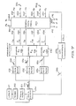
- FIG. 7 is a block diagram depicting schematically the flow of raw data through the various signal processing and conditioning subsystems.
- the photodetector (42) generates a raw data output signal (120) which corresponds to the variation in intensity of the backscattered light received from sample volume area (12) through the window lens (40) (Fig. 3).
- each of the three acousto-optic cells (38) had its particular associated acoustic frequency which resulted in each of the three different sets of fringe planes having its own distinguishing modulation frequency that will be imparted to the scattered light as the fringe planes move relative to a "stationary" aerosol particle.
- Sinc the three modulating frequencies are selected such that a "moving" particle will still result in the scattered light being modulated at a frequency that still is contained within three frequency bands centered about the three modulation frequencies and since the three modulating frequencies are sufficiently separated from one another that the three associated frequency bands associated with the three sets of fringe planes to not overlap-at least for the range of particle velocities anticipated-it is thus possible to separate the raw output signal (120) (depicted as a single burst of frequencies), by means of three separate conventional band pass filters (122, 124, 126); the raw output signal may thus oe divided into a low frequency component (128), a mid-frequency component (130) and a high frequency component (132), respectively corresponding to the fringe planes associated with first normal vector N a , second normal vector N bT and third normal vector N c .
- These three signal components are input into three respective channels (134, 136, 138) of a conventional frequency analyzer (140) which processes successive such frequency burst components to derive a corresponding fundamental frequency from the background noise and to output a digital indication thereof to the digital data processor (142).
- a conventional frequency analyzer 140
- This is indicated symbolically in the Figure by the provision of a first output (144) labelled fa from the first channel (134), a second output labelled f b (146) from the second channel (136), and a third output labelled f c (148) from the third channel (158).
- the frequency analyzer (140) is provided with an adaptive tracking capability whereby it concentrates its search for the desired fundamental frequency component about a known or predicted value thereof.
- This is indicated diagrammatically in the Figure by the provision of three digital signals from the data processor (142) to the frequency analyzer (140) labelled respectively f a (150), 1, (152) and f c (154).
- the data processor (142) has the benefit of accelerometer data and rate-gyro data from the aircraft's guidance system.
- first set of inputs 156) respectively labelled N x (158), Ny (160), and Nz (162) which represent digital indications of acceleration in the aircraft's X, Y and Z axes
- second set of similar inputs 164) respectively labelled R x (166), Ry (168) and R z (170) corresponding to digital representations of the aircraft's angular velocity about its X, Y and Z axes, respectively.
- such an estimation may make use of the mathematical technique known as the "Kalman Filter” whereby such frequency changes may be predicted with reasonable accuracy even when the frequency analyzer is unable to make an accurate measurement of the actual frequency because of a poor signal-to-noise ratio, sudden perturbations in the signal caused by fleeting gusts of wind and the like and by the failure of the photodetector (42) to output any meaningful signal for some interval of time as the result of the temporary absence of any suitable aerosol particles within the actual sample volume.
- Kalman Filter the mathematical technique known as the "Kalman Filter”
- the data processor (142) produces three velocity output signals (which may be either analog or digital, or both), identified in the drawings by the symbol V (172), a (174) and (176) respectively corresponding to true air speed, angle of attack and angle of side slip.
- V (172) the output of the data processor will effectively be a composite of data measured by the fringe velocimeter with data measured by conventional accelerometers and rate gyroscopes.
- a data switch (180) is located in a signal path between the photodetector (42) and the three band pass filters (122, 124, 126).
- a timer (182) provides a timing signal to switch the laser (32) On and Off (as described previously with reference to Fig. 6); at the same time it also controls the data switch (180).
- the sample output by the photodetector (42) is coupled through the switch (180) to the three band pass filters (122, 124, 126) as aforesaid.
- the switch (180) couples the output of the photodetector (42) to an analog to digital (A/D) converter circuit (184) which digitizes the exponentially decayed signal (186) then being output from the photodetector (42) as the result of the exponential decay of the intensity of the fluorescent re-emissions at discrete time intervals t" which is accordingly input to the data processor (142) in digital form.
- the data processor (142) is also provided with a digital temperature signal T t (188). From these two inputs and also from the air speed measurement V (172), the data processor (142) is thus able to derive a digital signal P (190) representing the pressure altitude of the aircraft in accordance with the physical equations discussed previously with reference to Fig. 1.
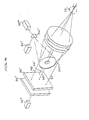
- Figs. 8 and 9 show alternative embodiments generally similar to that of Fig. 3 but employing more than one radiation source and/or more than one photodetector. Accordingly, components generally similar in construction and function to specific components of the Fig. 3 embodiment will bear the same reference numbers with the addition of a "prime” symbol ('). Where components that are somewhat analogous to components shown in the Fig. 3 embodiment have been replaced with several components, then double prime (") and triple prime (“'), etc. symbols will also be employed.
- a primary laser source (32') provides the radiation that forms the moving interference fringe planes utilized to make the velocity measurements associated with the velocimeter subsystem.
- the laser (32') should preferably be of a type that may be continuously operated and provides a well-collimated beam of coherent light of a sufficiently short wavelength relative to the diameter of a typical atmospheric aerosol particle that a substantial backscattering will occur as the aerosol particles that naturally occur in the atmosphere pass through the interference fringe planes created in the sample region (12) by the velocimeter subsystem.
- a second radiation source (32") that functions as the radiation source for the altimeter subsystem.
- the spectral content of the second laser (32") should preferably be such as to cause a measurable degree of fluorescence of particular air molecules within the sample region (12) at the altitudes and pressures for which the system will be utilized.
- a dichroic mirror (200) is utilized to combine the output beam (34') from the first laser (32') with the output beam (34") of the second laser (32") to form a combined output beam (34"') that is functionally analogous to the output beam (34) of the Fig. 3 embodiment, except that its spectral and coherency characteristics will be a combination of the respective characteristics of the two input beams (34', 34").
- Combined beam (34"') is divided into three beams (44', 46', 48') by the beam splitter (36'), these three beams being oriented at approximately 120° intervals about the central axis (50').
- These three beams are then modulated into three diverging beam pairs (64', 66', 68') by the acousto-optic modulator assembly (38') and are focussed by the front element (70') of the window lens (40') into three converging beam pairs (74', 76', 78') that each have their point of intersection centered within the sample region (12) to thereby form interference fringe planes as described previously with reference to the Fig. 3 embodiment. Since the three converging beams (74', 76', 78') also contain radiant energy originating from the second laser (32'), accordingly, the particular air molecules in the sample region (12) that are sensitive to the radiation (34") from the second laser (32”) will fluoresce.
- a second dichroic mirror (202) separates the received energy (204) into a first component (206) that has been backscattered from the aerosol molecules and a second component (208) that is associated with the fluorescent re-emissions from individual air molecules with the first component (206) being directed toward the first photodetector (42') and the second component being directed to the second photodetector (42").
- a single laser radiation source (32) results in two distinct types of received radiation differing substantially in their respective spectral content
- a suitable beam splitter such as dichroic mirror (202) of the Fig. 8 embodiment
- two individual photodetectors may be employed, each sensitive to only one type of radiation.
- FIG. 9 shows yet another possible embodiment of the optical components utilized to focus the radiation received from the sample volume (12) onto two photodetectors (42"', 42""). It should be noted that this particular embodiment does not employ three separate beam pairs such as were shown in the embodiments of Figs. 3 and 8 but rather three separate modulated output beams (52', 54', 56') and a single central unmodulated beam (58').
- Such an alternative form of construction is but one example of a number of different optical arrangements utilizing refracting and/or reflecting optical elements that may be utilized to transmit and focus laser radiation onto a sample volume and to gather and receive the resultant radiation from the sample volume and focus it onto the photodetector or other radiation measurement device.
- an auxiliary focussing element in the optical receiving subsystem namely, a convex reflector (202") that is tilted with respect to the central axis of the optics (50"), so as to permit the use of two off- axis detectors (42"', 42""), with the two radiation components (206', 208') that are focussed onto the two photodetectors (42"', 42"") being separated by a dichroic mirror (202''').
- the laser velocimeter subsystem and the fluorescent altimeter subsystem may each have utility apart from the other.
- the energy source within the velocimeter subsystem would not need to be switched on and off but could be operated continuously.
- other energy sources could be used in place of the laser within the altimeter subsystem, in particular, fluorescent emissions may be generated in response to radio-frequency electromagnetic radiation (or soft x-rays) directed away from the aircraft skin with the radiant energy preferably being oriented cylindrically about a propagation axis so that it does not significantly fall off in intensity in the vicinity of the sample volume.
- the optical axis of the detector subsystem could cross the radiant energy propagation axis at the sample volume, thereby effectively confining the sample volume to the intersection in three-dimensional space of the detector's effective field of view with the radiant energy beam.
- the apparatus constructed in accordance with the teachings of the present invention may be utilized in many different types of instrumentation systems, such as provided for use aboard an aircraft, in which case air flight data measurements of variables such as air density, altitude, air speed, angle of attack and side slip angle may be made with enhanced accuracy and reliability. Furthermore, it may find separate utility in aircraft instrumentation systems provided with a conventional altimeter.
Landscapes
- Engineering & Computer Science (AREA)
- Physics & Mathematics (AREA)
- General Physics & Mathematics (AREA)
- Health & Medical Sciences (AREA)
- Software Systems (AREA)
- Theoretical Computer Science (AREA)
- Nuclear Medicine, Radiotherapy & Molecular Imaging (AREA)
- Analytical Chemistry (AREA)
- Optics & Photonics (AREA)
- Multimedia (AREA)
- General Engineering & Computer Science (AREA)
- Life Sciences & Earth Sciences (AREA)
- Chemical & Material Sciences (AREA)
- Aviation & Aerospace Engineering (AREA)
- Biochemistry (AREA)
- General Health & Medical Sciences (AREA)
- Immunology (AREA)
- Pathology (AREA)
- Investigating, Analyzing Materials By Fluorescence Or Luminescence (AREA)
- Investigating Or Analysing Materials By Optical Means (AREA)
- Optical Radar Systems And Details Thereof (AREA)
Claims (18)
Applications Claiming Priority (6)
| Application Number | Priority Date | Filing Date | Title |
|---|---|---|---|
| US06/328,476 US4572667A (en) | 1981-12-08 | 1981-12-08 | Fluorescent air data measurement device |
| US06/328,721 US4506979A (en) | 1981-12-08 | 1981-12-08 | Compact radiation fringe velocimeter for measuring in three dimensions |
| US328721 | 1981-12-08 | ||
| US328476 | 1981-12-08 | ||
| US06/360,500 US4483614A (en) | 1981-12-08 | 1982-03-22 | Optical air data measurement system |
| US360500 | 1982-03-22 |
Related Child Applications (2)
| Application Number | Title | Priority Date | Filing Date |
|---|---|---|---|
| EP86115064A Division EP0227911A3 (de) | 1981-12-08 | 1982-12-06 | Optisches Luftdatenmesssystem |
| EP86115064.7 Division-Into | 1986-10-30 |
Publications (2)
| Publication Number | Publication Date |
|---|---|
| EP0083162A1 EP0083162A1 (de) | 1983-07-06 |
| EP0083162B1 true EP0083162B1 (de) | 1988-09-07 |
Family
ID=27406602
Family Applications (2)
| Application Number | Title | Priority Date | Filing Date |
|---|---|---|---|
| EP82306478A Expired EP0083162B1 (de) | 1981-12-08 | 1982-12-06 | Optisches Luftdaten Mess-System |
| EP86115064A Withdrawn EP0227911A3 (de) | 1981-12-08 | 1982-12-06 | Optisches Luftdatenmesssystem |
Family Applications After (1)
| Application Number | Title | Priority Date | Filing Date |
|---|---|---|---|
| EP86115064A Withdrawn EP0227911A3 (de) | 1981-12-08 | 1982-12-06 | Optisches Luftdatenmesssystem |
Country Status (4)
| Country | Link |
|---|---|
| EP (2) | EP0083162B1 (de) |
| JP (1) | JPH01301171A (de) |
| CA (1) | CA1209230A (de) |
| DE (1) | DE3279005D1 (de) |
Families Citing this family (5)
| Publication number | Priority date | Publication date | Assignee | Title |
|---|---|---|---|---|
| US4887213A (en) * | 1987-07-31 | 1989-12-12 | The Titan Corporation | System for, and methods of, providing for a determination of the movement of an airborne vehicle in the atmosphere |
| US5002389A (en) * | 1988-12-22 | 1991-03-26 | Honeywell Inc. | Pulsed fluorescence velocimeter |
| FR2659452B1 (fr) * | 1990-03-08 | 1992-07-03 | Sextant Avionique | Systeme a laser, de mesure de l'angle d'incidence d'un aeronef. |
| FR2713770B1 (fr) * | 1993-12-10 | 1996-02-09 | Sextant Avionique | Procédé et appareil de mesure optique de la pression d'un mélange gazeux. |
| GB0304344D0 (en) | 2003-02-26 | 2003-04-02 | Bae Systems Plc | Gas velocity sensor |
Family Cites Families (6)
| Publication number | Priority date | Publication date | Assignee | Title |
|---|---|---|---|---|
| US3334235A (en) * | 1963-12-19 | 1967-08-01 | Sperry Rand Corp | Photosensitive fluorescent lifetime measuring apparatus |
| US3612859A (en) * | 1968-01-31 | 1971-10-12 | Westinghouse Electric Corp | Method for measuring and controlling the density of a metallic vapor |
| FR2154376B1 (de) * | 1971-09-29 | 1975-07-18 | Sogreah | |
| US4148585A (en) * | 1977-02-11 | 1979-04-10 | The United States Of America As Represented By The Department Of Health, Education & Welfare | Three dimensional laser Doppler velocimeter |
| DE2841499C2 (de) * | 1978-09-23 | 1984-04-12 | Messerschmitt-Bölkow-Blohm GmbH, 8000 München | Laser-Luftwerte-Sensor |
| US4572667A (en) * | 1981-12-08 | 1986-02-25 | Lockheed Corporation | Fluorescent air data measurement device |
-
1982
- 1982-12-06 EP EP82306478A patent/EP0083162B1/de not_active Expired
- 1982-12-06 EP EP86115064A patent/EP0227911A3/de not_active Withdrawn
- 1982-12-06 DE DE8282306478T patent/DE3279005D1/de not_active Expired
- 1982-12-07 CA CA000417139A patent/CA1209230A/en not_active Expired
-
1989
- 1989-04-18 JP JP1098617A patent/JPH01301171A/ja active Pending
Also Published As
| Publication number | Publication date |
|---|---|
| JPH01301171A (ja) | 1989-12-05 |
| EP0083162A1 (de) | 1983-07-06 |
| EP0227911A3 (de) | 1988-08-24 |
| EP0227911A2 (de) | 1987-07-08 |
| CA1209230A (en) | 1986-08-05 |
| DE3279005D1 (en) | 1988-10-13 |
Similar Documents
| Publication | Publication Date | Title |
|---|---|---|
| US4483614A (en) | Optical air data measurement system | |
| US4506979A (en) | Compact radiation fringe velocimeter for measuring in three dimensions | |
| US5002389A (en) | Pulsed fluorescence velocimeter | |
| US7106447B2 (en) | Molecular optical air data systems (MOADS) | |
| US5153665A (en) | Vaporizing particle velocimeter | |
| US4148585A (en) | Three dimensional laser Doppler velocimeter | |
| EP1549974B1 (de) | Bistatische laser radareinrichtung | |
| US5504719A (en) | Laser hydrophone and virtual array of laser hydrophones | |
| JPH0345341B2 (de) | ||
| US4859055A (en) | Laser velocimeter | |
| US4026655A (en) | Pseudo-backscatter laser doppler velocimeter employing antiparallel-reflector in the forward direction | |
| US3547540A (en) | Laser fluid velocity detector | |
| US20080297762A1 (en) | System and method for determining crosswinds | |
| US8749794B2 (en) | Optical device for measuring anemometer parameters | |
| US6654102B1 (en) | Miniature optical sensor | |
| US3623361A (en) | Optical probing of supersonic flows with statistical correlation | |
| JPH0339655A (ja) | 周囲流体に対する航行体の相対速度を表わす信号を航行体上で得る装置 | |
| US4818101A (en) | Laser-doppler velocimetry | |
| EP0083162B1 (de) | Optisches Luftdaten Mess-System | |
| US3680961A (en) | Measurement of particle sizes | |
| US3737233A (en) | Vector velocimeter | |
| US6040899A (en) | Optical velocimetric probe | |
| EP0374607A1 (de) | Vorrichtung zur Bestimmung der Bewegung eines Flugzeuges in der Atmosphäre | |
| US4284350A (en) | Laser geophone | |
| US4989969A (en) | Time of flight velocimeter |
Legal Events
| Date | Code | Title | Description |
|---|---|---|---|
| PUAI | Public reference made under article 153(3) epc to a published international application that has entered the european phase |
Free format text: ORIGINAL CODE: 0009012 |
|
| AK | Designated contracting states |
Designated state(s): DE FR GB NL |
|
| 17P | Request for examination filed |
Effective date: 19830818 |
|
| GRAA | (expected) grant |
Free format text: ORIGINAL CODE: 0009210 |
|
| AK | Designated contracting states |
Kind code of ref document: B1 Designated state(s): DE FR GB NL |
|
| REF | Corresponds to: |
Ref document number: 3279005 Country of ref document: DE Date of ref document: 19881013 |
|
| ET | Fr: translation filed | ||
| PLBE | No opposition filed within time limit |
Free format text: ORIGINAL CODE: 0009261 |
|
| STAA | Information on the status of an ep patent application or granted ep patent |
Free format text: STATUS: NO OPPOSITION FILED WITHIN TIME LIMIT |
|
| 26N | No opposition filed | ||
| PGFP | Annual fee paid to national office [announced via postgrant information from national office to epo] |
Ref country code: GB Payment date: 19901119 Year of fee payment: 9 |
|
| PGFP | Annual fee paid to national office [announced via postgrant information from national office to epo] |
Ref country code: FR Payment date: 19901218 Year of fee payment: 9 |
|
| PGFP | Annual fee paid to national office [announced via postgrant information from national office to epo] |
Ref country code: DE Payment date: 19901221 Year of fee payment: 9 |
|
| PGFP | Annual fee paid to national office [announced via postgrant information from national office to epo] |
Ref country code: NL Payment date: 19901231 Year of fee payment: 9 |
|
| PG25 | Lapsed in a contracting state [announced via postgrant information from national office to epo] |
Ref country code: GB Effective date: 19911206 |
|
| PG25 | Lapsed in a contracting state [announced via postgrant information from national office to epo] |
Ref country code: NL Effective date: 19920701 |
|
| GBPC | Gb: european patent ceased through non-payment of renewal fee | ||
| NLV4 | Nl: lapsed or anulled due to non-payment of the annual fee | ||
| PG25 | Lapsed in a contracting state [announced via postgrant information from national office to epo] |
Ref country code: FR Effective date: 19920831 |
|
| PG25 | Lapsed in a contracting state [announced via postgrant information from national office to epo] |
Ref country code: DE Effective date: 19920901 |
|
| REG | Reference to a national code |
Ref country code: FR Ref legal event code: ST |