EP0083082A2 - Procedure and device for measuring the length of a straight or a curred path - Google Patents
Procedure and device for measuring the length of a straight or a curred path Download PDFInfo
- Publication number
- EP0083082A2 EP0083082A2 EP82111940A EP82111940A EP0083082A2 EP 0083082 A2 EP0083082 A2 EP 0083082A2 EP 82111940 A EP82111940 A EP 82111940A EP 82111940 A EP82111940 A EP 82111940A EP 0083082 A2 EP0083082 A2 EP 0083082A2
- Authority
- EP
- European Patent Office
- Prior art keywords
- sensor
- movement
- marking
- markings
- measuring
- Prior art date
- Legal status (The legal status is an assumption and is not a legal conclusion. Google has not performed a legal analysis and makes no representation as to the accuracy of the status listed.)
- Granted
Links
- 238000000034 method Methods 0.000 title claims description 30
- 230000010355 oscillation Effects 0.000 claims abstract description 47
- 238000005259 measurement Methods 0.000 claims abstract description 31
- 230000005484 gravity Effects 0.000 claims description 15
- 239000003550 marker Substances 0.000 claims description 15
- 230000003534 oscillatory effect Effects 0.000 claims description 8
- 239000000523 sample Substances 0.000 claims description 6
- 238000007789 sealing Methods 0.000 claims description 6
- 230000003287 optical effect Effects 0.000 claims description 5
- 239000003302 ferromagnetic material Substances 0.000 claims description 3
- 238000012544 monitoring process Methods 0.000 claims description 2
- 230000001154 acute effect Effects 0.000 claims 1
- 238000013461 design Methods 0.000 abstract description 5
- 230000007613 environmental effect Effects 0.000 abstract description 2
- 238000006073 displacement reaction Methods 0.000 description 5
- 239000000428 dust Substances 0.000 description 5
- 238000012545 processing Methods 0.000 description 4
- 239000000969 carrier Substances 0.000 description 2
- 238000010586 diagram Methods 0.000 description 2
- 238000000691 measurement method Methods 0.000 description 2
- 238000010408 sweeping Methods 0.000 description 2
- 230000001133 acceleration Effects 0.000 description 1
- 230000005540 biological transmission Effects 0.000 description 1
- 230000015572 biosynthetic process Effects 0.000 description 1
- 238000011156 evaluation Methods 0.000 description 1
- 230000005284 excitation Effects 0.000 description 1
- 230000002349 favourable effect Effects 0.000 description 1
- 239000012530 fluid Substances 0.000 description 1
- 239000011521 glass Substances 0.000 description 1
- 230000001788 irregular Effects 0.000 description 1
- 230000007774 longterm Effects 0.000 description 1
- 238000004519 manufacturing process Methods 0.000 description 1
- 230000035515 penetration Effects 0.000 description 1
- 238000005096 rolling process Methods 0.000 description 1
- 230000003068 static effect Effects 0.000 description 1
- 230000004304 visual acuity Effects 0.000 description 1
Images
Classifications
-
- G—PHYSICS
- G01—MEASURING; TESTING
- G01D—MEASURING NOT SPECIALLY ADAPTED FOR A SPECIFIC VARIABLE; ARRANGEMENTS FOR MEASURING TWO OR MORE VARIABLES NOT COVERED IN A SINGLE OTHER SUBCLASS; TARIFF METERING APPARATUS; MEASURING OR TESTING NOT OTHERWISE PROVIDED FOR
- G01D5/00—Mechanical means for transferring the output of a sensing member; Means for converting the output of a sensing member to another variable where the form or nature of the sensing member does not constrain the means for converting; Transducers not specially adapted for a specific variable
- G01D5/26—Mechanical means for transferring the output of a sensing member; Means for converting the output of a sensing member to another variable where the form or nature of the sensing member does not constrain the means for converting; Transducers not specially adapted for a specific variable characterised by optical transfer means, i.e. using infrared, visible, or ultraviolet light
- G01D5/32—Mechanical means for transferring the output of a sensing member; Means for converting the output of a sensing member to another variable where the form or nature of the sensing member does not constrain the means for converting; Transducers not specially adapted for a specific variable characterised by optical transfer means, i.e. using infrared, visible, or ultraviolet light with attenuation or whole or partial obturation of beams of light
- G01D5/34—Mechanical means for transferring the output of a sensing member; Means for converting the output of a sensing member to another variable where the form or nature of the sensing member does not constrain the means for converting; Transducers not specially adapted for a specific variable characterised by optical transfer means, i.e. using infrared, visible, or ultraviolet light with attenuation or whole or partial obturation of beams of light the beams of light being detected by photocells
- G01D5/347—Mechanical means for transferring the output of a sensing member; Means for converting the output of a sensing member to another variable where the form or nature of the sensing member does not constrain the means for converting; Transducers not specially adapted for a specific variable characterised by optical transfer means, i.e. using infrared, visible, or ultraviolet light with attenuation or whole or partial obturation of beams of light the beams of light being detected by photocells using displacement encoding scales
- G01D5/34746—Linear encoders
- G01D5/34753—Carriages; Driving or coupling means
-
- G—PHYSICS
- G01—MEASURING; TESTING
- G01D—MEASURING NOT SPECIALLY ADAPTED FOR A SPECIFIC VARIABLE; ARRANGEMENTS FOR MEASURING TWO OR MORE VARIABLES NOT COVERED IN A SINGLE OTHER SUBCLASS; TARIFF METERING APPARATUS; MEASURING OR TESTING NOT OTHERWISE PROVIDED FOR
- G01D5/00—Mechanical means for transferring the output of a sensing member; Means for converting the output of a sensing member to another variable where the form or nature of the sensing member does not constrain the means for converting; Transducers not specially adapted for a specific variable
- G01D5/26—Mechanical means for transferring the output of a sensing member; Means for converting the output of a sensing member to another variable where the form or nature of the sensing member does not constrain the means for converting; Transducers not specially adapted for a specific variable characterised by optical transfer means, i.e. using infrared, visible, or ultraviolet light
- G01D5/32—Mechanical means for transferring the output of a sensing member; Means for converting the output of a sensing member to another variable where the form or nature of the sensing member does not constrain the means for converting; Transducers not specially adapted for a specific variable characterised by optical transfer means, i.e. using infrared, visible, or ultraviolet light with attenuation or whole or partial obturation of beams of light
- G01D5/34—Mechanical means for transferring the output of a sensing member; Means for converting the output of a sensing member to another variable where the form or nature of the sensing member does not constrain the means for converting; Transducers not specially adapted for a specific variable characterised by optical transfer means, i.e. using infrared, visible, or ultraviolet light with attenuation or whole or partial obturation of beams of light the beams of light being detected by photocells
- G01D5/36—Forming the light into pulses
Definitions
- the invention relates to a method and a device for measuring a length according to the preambles of claims 1 and 9, respectively.
- Such methods or devices are e.g. used in industry wherever a machine part is reciprocable against the rest of the machine either on a linear path or rotatable about an axis and the current position of the movable machine part is to be characterized either continuously or at certain predetermined times in that the linear distance or the angular distance of a point arbitrarily defined on the movable machine part is measured from a fixedly predetermined zero point or a currently arbitrarily defined reference point.
- the one of the two bodies which can be moved relative to one another is a marking carrier, i.e. e.g. either a linear scale, which may be several meters long, or a generally circular dial, with the marking carrier being a plurality of in the direction of relative movement, i.e. has linearly or angularly spaced markings which are generally in the form of narrow strips or lines extending perpendicular to the direction of the relative movement.
- the other of the two bodies then carries a scanning device, the sensor of which is able to recognize the markings and to generate a signal whenever such a marking passes it.
- the point mentioned above of the body carrying the scanning device can then also be defined, its linear or angular distance from a reference or zero defined on the other body point to be measured. If one places a straight line perpendicular to the direction of the relative movement through this point of one body, which is to be defined with the aid of the scanning device, and which runs radially through the center of rotation in the case of a rotary movement, it is strictly speaking the distance from this straight line, referred to below as measuring standards, from the zero point the relative movement that is to be measured in the methods in question.
- DE-OS 30 18 496 and DE-OS 30 18 527 disclose methods of the type mentioned at the outset for measuring an angle or arc distance and for measuring a linear distance, in which between those to be scanned Marking carrier and the sensor of the scanning device takes place a rotational movement independent of the relative movement of the two bodies, the angular velocity of which is constantly measured.
- the length measuring method known from DE-OS 30 18 527 which works according to this principle, has some disadvantages in terms of the technical effort required, despite the fact that it leads to extremely exact measuring results. Since the linear scale to be scanned must necessarily be fixed here, the above-mentioned relative rotational movement is achieved in that the sensor of the scanning device moves permanently on a circular path in such a way that it periodically sweeps over the part of the linear scale of interest.
- the invention has for its object to provide a method and an apparatus of the type mentioned which, while maintaining the high measurement accuracy and the high resolving power, enable the use of a simpler, less technical and data processing-related effort and thus more cost-effective measuring arrangement.
- each of the markings of the marking carrier linear scale or circular disk
- this marker carrier has been manufactured with particular precision.
- the markings made on it can be comparatively wide lines, the mutual distances between which need not be identical.
- each of the markings is identified individually and its distance from the respective neighboring marking is determined by calibration measurements, which are carried out with the device according to the invention itself, with an accuracy corresponding to the accuracy of the time measurement method used, which then also determines the exact distance of each individual marking from the zero point the relative movement can be determined.
- connection to absolute sizes results from the measurement of angles or arc lengths from the fact that each marking of the marking carrier also has an angular distance of 360 ° of itself, while in the case of straight length measurements the total length of the linear scale used is determined by a single interferometric measurement can.
- the oscillating sensor In order to obtain the simplest possible conditions, it is advantageous to arrange the oscillating sensor so that its measuring line of gravity runs through the center of the oscillating system, as seen in the direction of the oscillatory movement, and, moreover, the measuring standards pass through the center of the oscillating movement, i.e. So to put through the point with respect to which the reversal points of the measurement line are symmetrical.
- the distance sought applies if v is the effective mean speed of the vibrating system in the period A t. With a correspondingly precise knowledge of v, the desired distance d thus results with the accuracy of the time measurement carried out.
- a vibration system according to the invention in particular when actuated with a sinusoidal excitation signal, runs through a period in each individual oscillation stroke between the acceleration and deceleration phases in which its speed can be regarded as constant with very good approximation. If you give a sufficiently large maximum amplitude for. the oscillation movement and an adapted maximum distance of the markings on the marking carrier, it can always be achieved that the time interval ⁇ t falling in equation (1) falls in the period in which the oscillation speed is constant. The effective mean value v from equation (1) can then be replaced by the constant speed v. 0
- a long-term constancy of the value of v is in no way necessary, since it is possible according to the invention to either measure the speed v o directly or another variable that characterizes this speed separately for each oscillation stroke and the corresponding value for calculating d according to equation ( 1) to be combined with the time interval A t measured at precisely this oscillation stroke.
- the oscillating sensor to also oscillate a second marking carrier, which is scanned by a second sensor, which is immovably attached to the body carrying the scanning device.
- this second marking carrier is not a large scale disk bearing a plurality of markings, but rather, for example, a small plate-shaped glass scale which, in addition to the at least one marking used to generate the reference signal, advantageously also has two further markings arranged in this way are that the time interval between the assigned signals emitted by the second sensor can be measured, forms an exact measure of the above-mentioned constant oscillation speed v.
- the measuring probe which scans the resonating marking carrier is expediently attached to the body carrying the scanning device in such a way that its measuring line of gravity coincides with the measuring standard extending through the center point of the oscillating movement.
- the resonating marking carrier Due to the above-mentioned formation of the resonating marking carrier as a small, light plate, it is possible to keep the mass of the entire oscillation system extremely low, so that a high oscillation frequency can be realized with a correspondingly large number of measurement values obtainable per unit of time, from which further The mean value can be increased to increase the measuring accuracy.
- the electromagnetic coils advantageously used to generate the oscillating movement and the entire bearing and guiding device for the oscillating system can be made very small, so that, overall, a very compact arrangement that can be easily shielded from dirt, dust and moisture is obtained.
- the two markings which serve to obtain a value which characterizes the speed v 0 are advantageously attached symmetrically to the center of the oscillation carrier and spaced apart from it so far that the Ge at a predetermined maximum amplitude of the oscillatory movement Speed of the vibration system can be regarded as constant in the period of time that elapses on an oscillation stroke between the passage of the front of the two markings in the direction of movement in question and the passage of the rear of the two markings on the second sensor.
- these two last-mentioned markings can be placed at different distances from the center of the oscillation system, so that the two pulses that one marking generates when passing through the reversal point assigned to it have a different time interval than the two double pulses that the other Marked when passing through their reversal point.
- These different time intervals then serve as a signal that characterizes the direction of movement of the subsequent oscillation stroke. This direction of movement is important because it decides whether the measured distance d must be added or subtracted from the known distance of the scanned marking of the first marking carrier from the zero point of the relative movement in order to obtain the distance of the measurement standards from the zero point of the relative movement.
- the first marking carrier is a linear scale, which, as already mentioned, can possibly have a considerable length
- the body carrying the scanning device is provided with an arm, at the tip of which the scanning device according to the invention is attached. This arm projects between the two sealing bodies into the interior of the hollow profile, so that the linear scale located there can be scanned. If the arm is provided with corresponding wedge surfaces, the two sealing bodies are also completely tight on its outer surfaces and it can be displaced in the longitudinal direction of the hollow profile without the tight closure of the interior of the hollow profile being interrupted.
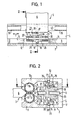
- 1 and 2 show two bodies 2 and 3 which can be displaced linearly relative to one another in the direction of the double arrow F, the first of which is of a long, essentially U-shaped hollow profile 4 which extends in the direction of the double arrow F and the other of which is perpendicular to the longitudinal direction of the hollow profile 4 extending and with its free end 5 protruding into the interior of the hollow profile arm 6 is formed, which carries at this free end 5 a scanning device 8, which serves to scan a marker carrier designed in the form of a linear scale 9, which is extends essentially over the entire length of the hollow profile 4 and is attached to the profile rear wall 12 connecting the two profile legs 10, 11 so that it protrudes from it towards the arm 6 carrying the scanning device 8.
- On the Linear scale 9 has a plurality of markings 14 spaced apart in the direction of the linear movement, with the aid of which the distance of a measuring standard 16 moving with the arm 6 from a zero point of the linear displacement (not shown in the figures) or the length of the body 3 at one Linear movement covered distance is to be measured.
- the hollow profile 4 can be connected to an elongated machine frame, while the arm 6 is rigidly connected to a machine slide that can be displaced along the machine frame.
- the markings 14 each have the shape of a narrow, elongated strip which is essentially perpendicular to the direction of the linear movement and which differs in terms of light transmission from the areas of the linear marking carrier 9 surrounding it.
- markings 14 can thus be scanned with the aid of a sensor 18 of the scanning device 8, in the present case designed as a differential photodiode, which, as can be seen in particular from FIG. 2, is mounted in one leg of a sensor carrier 19 encompassing the linear scale 9 in a fork-like manner. while a light source 20 is arranged in the opposite leg of the sensor carrier so that the connecting line between the light source 20 and the sensor 18 is approximately perpendicular to the surface of the linear marker carrier 9 bearing the markings 14.
- the sensor carrier 19 is fixedly connected to the central part of two straight rods 23, 24 arranged one above the other in FIG. 2, the free ends of which are via slide bearings of the two Legs 25, 26 of a bearing block 27, which is essentially U- shaped in the plan view of FIG. 1, are supported such that the two rods 23, 24 extend parallel to the direction of the linear movement.
- the two legs 25,26 of the probe carrier 19 which surround the fork-like end of the bearing block 27 rigidly mounted at the front end 5 of the arm 6 are spaced so far apart that the probe carrier 19 between them an oscillating movement due to the sliding mounting of the rods 23, 24 supporting it Can perform the direction of the linear displacement.
- This oscillation movement is generated in that an electromagnetic coil 29, 30 is arranged on the sides of the legs 25, 26 of the bearing block 27 facing away from the sensor carrier 19 such that the upper rod 23, consisting of a ferromagnetic material, has the free ends as the core in protrudes these two coils and can thus be moved back and forth in the direction of arrow F by controlling these two coils 29, 30 with a corresponding electrical signal.
- the electrical connections serving to control the coils 29, 30 are neither shown in the figures, nor are the wires leading to the light source 20 and the sensor 18.
- the light beam going from the light source 20 to the sensor 18 sweeps over, even when there is no relative movement between the two bodies 2, 3, light-impermeable markings 14 and translucent marking spaces, thereby changing it is modulated.
- the lower rod 24 only serves to guide the oscillating element 22 formed from the sensor carrier 19 and the upper rod 23.
- it could also consist of a ferromagnetic material and immerse at least with one of its free ends as a core in a further electromagnetic coil, which would then emit an electrical signal reflecting the actual oscillation movement of the oscillating element 22, the evaluation of which could be used, for example, to determine the effective mean oscillation speed v of a predetermined section of each oscillation stroke.
- the bearing block 27 In his between the front end 5 of the arm 6 and the M eß complicatlerthe 19 area lying, the bearing block 27 has a horizontal in Fig. 2, extending in the direction of the linear movement slot 32 in which a extending parallel to the first marker support 9, fixed is mounted on the sensor carrier 19 and co-oscillates with the second marker carrier 35.
- This second marking carrier 35 which is designed as a small plate, has, as will be explained in more detail below, some markings 45 to 49 which differ from the regions of the second marking carrier 35 which surround them, which markers are perpendicular to the direction of the oscillation movement and thus to the direction of the linear displacement extending narrow lines are formed.
- markings 45 to 49 are scanned by a second sensor 36, also formed by a differential photodiode, which is mounted in the bearing block 27 below the slot 32 such that the connecting line between it and a light source 37 arranged in the bearing block 27 above the slot 32 in is approximately perpendicular to the surface of the second marking carrier 35 bearing the markings 45 to 49.
- translucent markings 45 to 49 and opaque marking gaps run through the measuring light beam from the second measuring sensor 36 and its light in constant alternation Source 37 formed, firmly connected to the body 3 through the second scanner, whereby this light beam is also modulated.
- Light-emitting diodes which can either be LEDs or laser diodes, are preferably used as light sources 20 and 37.
- a hose 39 or 40 Attached to the end regions of the legs 10, 11 of the hollow profile 4 facing the arm 6 is a hose 39 or 40, which can be filled with a pressurized fluid and extends over the entire length of the hollow profile 4, on the inside facing the opposite leg at its ends, which are not shown in FIG. 1, but are located on the left or right in the top view there, on sealingly arranged end faces which cover the cross section of the hollow profile.
- the cross-sectional dimensions of the hoses 39, 40 are dimensioned such that, when filled, they touch along the surface 41 in the areas lying next to the arm 6 and thus seal the interior of the hollow profile 4 in an airtight and dustproof manner.
- the arm 6 is provided with wedge-shaped surfaces represented by dotted lines in FIG. 1, which form without sharp edges in the upper or lower one in FIG. 2 Pass over the surface of the arm 6, on which the left or right side edge of the arm 3 in FIG. 1 has its smallest thickness and rise towards the center of the arm 3 up to its maximum thickness.
- the hoses 39, 40 in the area in which the arm 6 passes between them are pressed apart and deformed in the manner shown in FIG. 2.
- the hoses are 39.40 so on the wedge surfaces of the arm 6 that the interior of the hollow section 4 remains completely sealed, although the arm 6 is freely movable in the direction of arrow F over the entire length of the hollow section 4.
- the upper hose 39 shown in section, is interrupted in the area of the arm 6, so that only the lower, not cut hose 40 is visible here.
- the two legs 25, 26 of the bearing block 27 are each connected to one another at their upper and lower ends by a connecting web 70 and 71 (see in particular FIG. 2) extending in the direction of the linear movement.
- a V-shaped groove 76, 79 extending in the direction of the linear movement is formed and arranged so that in FIG. 2 the connecting line of the two grooves coincides with the connecting line of the centers of the two rods 23, 24.
- the two grooves 76, 79 each serve to receive a plurality of balls, of which only one in FIG. 2, namely the upper ball 74 and the lower ball 75, and to hold them so that these balls move linearly the arm 6 in the direction of arrow F are taken from the bearing block 27.
- the apex angles of the grooves 77, 78 in the hollow profile 4 are substantially obtuse than the apex angles of the grooves 76, 79 in the bearing block 27. It is thereby achieved that the slippage of the balls 74, 75 which necessarily occurs in this arrangement occurs in the grooves 76, 79 of the bearing block 27, while a perfect rolling of the balls 74, 75 is ensured in the grooves 77, 78 of the hollow profile 4. As a result, an extremely exact and smooth guidance of the bearing block projecting freely from the body 2 with respect to the hollow profile 4 fastened to the other body 3 is advantageously achieved.
- an inventive device for measuring angular displacements has the main difference that instead of the linear scale 9, a circular dial is scanned, which is concentric on one of the two bodies is mounted to the axis of rotation of the relative movement.
- the other of the two bodies then carries the scanning device, which can be constructed in the same way as the scanning device 8 described above, and which is arranged such that the measuring standard 16 defined by the measurement line of gravity of the second sensor intersects the axis of rotation of the relative movement as a radial beam.
- the straight line distances measured between the markings of the scale disc and the measurement standards during a linear oscillating movement of the vibration system must advantageously be converted to arc distances, the above described scanning device are modified so that the first sensor moves back and forth on a partial circular path, the center of which lies in the axis of rotation of the relative movement. Since there are no linear displacements between the fixed marker carrier and its scanning device, the entire arrangement can be done without white teres are housed in a closed housing and shielded against environmental influences, the housing can have very small dimensions due to the use of only one dial and the small size of the oscillating scanning device.
- the body 3 is positioned with respect to the body 2 such that the measurement standard 16, which is defined by the separating web of the differential photodiode fastened to the body 3 as a second sensor 36, is at a distance d from the marking 14 n + 1 .
- the vibration system of which only the oscillating sensor 18 and the second marking carrier 35 connected to it are shown in a highly schematic manner in FIG. 3. For the sake of clarity, the bearing and drive devices for the vibration system are omitted here.
- the measuring heavy line 42 of the oscillating sensor 18 defines the center of the oscillating system consisting of this sensor 18 and the second marking carrier 35. -
- the vibration system is symmetrical with respect to its geometric extension to this center.
- the second marking carrier 35 there is a first marking 45 lying on the measuring line of gravity of the oscillating sensor 18, which is used whenever its optical center passes over the measuring line of gravity of the fixed sensor 36 due to the oscillating movement of the oscillating system, which is the case here Case to generate the reference signal characterizing the zero deflection of the oscillating system.
- two further markings 46 and 47 are arranged to the left and right of the first marking 45 used to generate the reference signal, each of which has the distance s o / 2 from the first marking 45, so that the total distance between the two markings 46, 47 is equal to s o .
- This distance is measured very precisely at least once by any known method, for example interferometrically, with the aid of a measuring microscope or advantageously using the device described in DE-OS 30 18 528.
- a whole circular dial which has a large number of markings, is first precisely measured and then divided into individual pieces, each of which bears the markings required for carrying out the method according to the invention, the spacing of which is thus very precisely known.
- This distance is chosen so that with a given maximum amplitude of the sinusoidal Oszillationsschwingung the Oszillationsgeschwindi g- speed in the period of time with very good approximation, can be considered constant, the front at each oscillation stroke between the sweeping over the Meßhisline of the fixed probe 36 through the, in this lifting movement of the two marks 46, 47 and the sweeping of this measurement line through the rear of the two marks 46, 47 passes.
- the marking carrier 35 has two markings 48, 49 arranged in the vicinity of the left and right edges, respectively, which are arranged such that they only pass over the center of gravity of the fixed sensor 36 shortly before and after the oscillation system has passed through its reversal point, when the vibration system has experienced the minimum-maximum deflection, which guarantees the constancy of the oscillation speed during the period defined above.
- the two markings 48, 49 can be arranged somewhat asymmetrically to the center of the marking carrier 35, so that the double signal which is generated by one marking 48 when passing through the reversal point assigned to it is at a different distance from that from the other marking 49 double signal generated when passing through the other reversal point. The direction of the subsequent oscillation movement can then be concluded from these time differences.
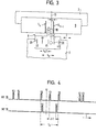
- Fig. 4 in a time diagram in the first line, the signals of the fixed sensor 36 and in the second line, the signals of the oscillating sensor 18 are plotted, which result in the situation shown in Fig. 3 when the vibration system from the in Fig. 3 position continues swinging to the right to the reversal point there.
- the dashed line 51 in FIG. 4 corresponds approximately to the point in time, as it were in FIG. 3, as it were by a snapshot.
- the two signals 53, 54 are shown, which were generated by the fixed measuring sensor 36 or its downstream transmitter when passing through the preceding reversal point of the oscillating system due to the passing of the marking 49.
- the oscillating sensor 18 passes over the marking 14n, which is represented in the second line by the corresponding pulse 55. After the signal 57, the oscillating sensor 18 sweeps over the marking 14 n + 1 of the fixed marking carrier 9, as a result of which the sensor signal 60 shown in the second line of FIG. 4 is generated.
- the time interval A t between the reference signal 57 and the sensor signal 60 and on the other hand the time interval t between the two pulse-shaped signals 56 and 58 are measured. From these measured values and the known geometric distance s of the markings 46, 47 assigned to the signals 56, 58, the desired distance d is then obtained in accordance with the equation (3) explained above.
- two further pulse-shaped signals 62, 63 are shown on the far right, which are emitted by the sensor 36 when the marking 48 passes shortly before and shortly after the vibration system has passed through the second reversal point.
- the time interval between the two pulse-shaped signals 62, 63 is smaller than the corresponding time interval between the two pulse-shaped signals 53 and 54, which is due to the fact that the associated markings 49 and 48 differ. have left distances from the marking 45 located in the middle of the vibration system.
- the time intervals between the signals 53, 54 on the one hand and the signals 62, 63 on the other hand must not be less than a certain minimum value in order to ensure that the oscillation system really oscillates with a maximum amplitude which ensures the constancy of v o in the period t 0 .
- this further embodiment corresponds in function and structure completely to the embodiment described with reference to the figures.
- the schematic representation of FIG. 3 clearly shows that the device according to the invention can also be used without difficulty for measuring arc lengths or angles.
- the point at which the axis of rotation perpendicular to the plane of the drawing, about which the two bodies 2 and 3 move relative to one another, could be either above or below.
- the first marking carrier 9 are designed as a full circular disk around which the scanning device 8 rotates on the outside.
- the first marking carrier 9 would be a disk-shaped circular ring, the inner edge of which is encompassed by the sensor carrier.
Abstract
Zur Längenmessung von bei der Relativbewegung zweier Köper durchlaufenen Strecken oder Bögen werden bisher vermittels einer relativbewegungsunabhängigen Rotationsbewegung zwischen einem an dem einen Körper befestigten Markierungsträger und einer am anderen Körper montierten Abtastvorrichtung identifizierte, einen bekannten Abstand vom Relativbewegungsnullpunkt aufweisende Markierungen abgetastet und die Rotationsgeschwindigkeit und der Zeitabstand eines in einer vorbestimmten Stellung der Rotationsbewegung erzeugten Referenzsignals von wenigstens einem Markierungssignal gemessen. Hieraus und aus bekannten Eichwerten wird der Abstand des die Abtasteinrichtung tragenden Körpers von wenigstens einer Markierung und damit vom Relativbewegungsnullpunkt berechnet. Zur Aufrechterhaltung und Überwachung der Konstanz der Rotationsgeschwindigkeit ist dabei ein vergleichsweise hoher Aufwand erforderlich. Demgegenüber wird erfindungsgemäß die Abtastvorrichtung in eine zur Relativbewegung parallele Oszillationsbewegung mit einer so großen Maximalamplitude versetzt, daß während eines ausreichenden Zeitraums um den Nulldurchgang die Oszillationsgeschwindigkeit jeweils hinreichend konstant ist. Zu ihrer Messung genügen zwei einfach identifizierbare Markierungen eines zweiten, kleinen Markierungsträgers. So läßt sich eine kompakte, gegen Umwelteinflüsse gut shützbare Bauform erzielen.To measure the length of lines or arches traversed by the relative movement of two bodies, a known movement from a marking carrier attached to one body and a scanning device mounted on the other body, and a known distance from the relative movement zero point, has been scanned by means of a rotation movement independent of relative movement and the rotational speed and the time interval one in a predetermined position of the rotational movement generated reference signal measured by at least one marking signal. From this and from known calibration values, the distance of the body carrying the scanning device from at least one marking and thus from the relative movement zero point is calculated. In order to maintain and monitor the constancy of the rotational speed, a comparatively high effort is required. In contrast, according to the invention, the scanning device is set into an oscillation movement parallel to the relative movement with such a large maximum amplitude that the oscillation speed is sufficiently constant for a sufficient period around the zero crossing. Two easily identifiable markings from a second, small marking carrier are sufficient for their measurement. This enables a compact design that can be protected against environmental influences.
Description
Die Erfindung betrifft ein Verfahren und eine Vorrichtung zur Messung einer Länge gemäß den Oberbegriffen der Ansprüche 1 bzw. 9.The invention relates to a method and a device for measuring a length according to the preambles of
Derartige Verfahren bzw. Vorrichtungen werden z.B. in der Industrie überall dort verwendet, wo ein Maschinenteil gegen den Rest der Maschine entweder auf einer linearen Bahn hin- und herbewegbar oder um eine Achse drehbar ist und entweder kontinuierlich oder zu bestimmten vorgegebenen Zeitpunkten die momentane Position des beweglichen Maschinenteils dadurch gekennzeichnet werden soll, daß der lineare Abstand oder der Winkelabstand eines an dem beweglichen Maschinenteil willkürlich definierten Punktes von einem fest vorbestimmten Nullpunkt oder einem momentan willkürlich festgelegten Bezugspunkt aus gemessen wird.Such methods or devices are e.g. used in industry wherever a machine part is reciprocable against the rest of the machine either on a linear path or rotatable about an axis and the current position of the movable machine part is to be characterized either continuously or at certain predetermined times in that the linear distance or the angular distance of a point arbitrarily defined on the movable machine part is measured from a fixedly predetermined zero point or a currently arbitrarily defined reference point.
In beiden Fällen ist mit dem einen der beiden relativ zueinander bewegbaren Körper ein Markierungsträger, d.h. z.B. entweder ein unter Umständen mehrere Meter langer Linearmaßstab oder eine im allgemeinen kreisförmige Skalenscheibe verbunden, wobei der Markierungsträger eine Vielzahl von in Richtung der Relativbewegung, d.h. linear oder winkelmäßig voneinander beabstandete Markierungen aufweist, die im allgemeinen die Form von sich senkrecht zur Richtung der Relativbewegung erstreckenden schmalen Streifen bzw. Strichen besitzen. Der andere der beiden Körper trägt dann eine Abtastvorrichtung, deren Meßfühler in der Lage ist, die Markierungen zu erkennen und immer dann ein Signal zu erzeugen, wenn eine solche Markierung an ihm vorbeiläuft.In both cases, the one of the two bodies which can be moved relative to one another is a marking carrier, i.e. e.g. either a linear scale, which may be several meters long, or a generally circular dial, with the marking carrier being a plurality of in the direction of relative movement, i.e. has linearly or angularly spaced markings which are generally in the form of narrow strips or lines extending perpendicular to the direction of the relative movement. The other of the two bodies then carries a scanning device, the sensor of which is able to recognize the markings and to generate a signal whenever such a marking passes it.
Mit Hilfe dieser Abtastvorrichtung kann dann auch der oben erwähnte Punkt des die Abtastvorrichtung tragenden Körpers definiert werden, dessen linearer oder winkelmäßiger Abstand von einem am anderen Körper definierten Bezugs- oder Nullpunkt gemessen werden soll. Legt man durch diesen mit Hilfe der Abtasteinrichtung zu definierenden Punkt des einen Körpers eine zur Richtung der Relativbewegung senkrechte Gerade, die im Fall einer Drehbewegung radial durch den Drehmittelpunkt verläuft, so ist es genau genommen der Abstand dieser im folgenden kurz als Meßnormale bezeichneten Geraden vom Nullpunkt der Relativbewegung, der bei den in Rede stehenden Verfahren ausgemessen werden soll.With the aid of this scanning device, the point mentioned above of the body carrying the scanning device can then also be defined, its linear or angular distance from a reference or zero defined on the other body point to be measured. If one places a straight line perpendicular to the direction of the relative movement through this point of one body, which is to be defined with the aid of the scanning device, and which runs radially through the center of rotation in the case of a rotary movement, it is strictly speaking the distance from this straight line, referred to below as measuring standards, from the zero point the relative movement that is to be measured in the methods in question.
Um bei derartigen Meßverfahren zu einer möglichst hohen Genauigkeit und einem möglichst großen Auflösungsvermögen zu kommen, war es früher erforderlich, den Linearmaßstab bzw. die kreisförmige Skalenscheibe mit einer möglichst großen Anzahl von Skalenstrichen zu versehen, die sowohl hinsichtlich ihrer möglichst klein zu haltenden Breite als auch der Gleichförmigkeit ihrer gegenseitigen Abstände und ihres zur Richtung der Relativbewegung möglichst senkrechten Verlaufes sehr hohen Anforderungen genügen mußten.In order to achieve the highest possible accuracy and the greatest possible resolution in such measurement methods, it was previously necessary to provide the linear scale or the circular dial with as large a number of scale lines as possible, both with regard to their width to be kept as small as possible the uniformity of their mutual distances and their course, which is as perpendicular as possible to the direction of the relative movement, had to meet very high requirements.
Zur Vermeidung der hierdurch bedingten hohen Herstellungskosten sind aus der DE-OS 30 18 496 bzw. der DE-OS 30 18 527 Verfahren der eingangs genannten Art zur Messung eines Winkels bzw. Bogenabstandes und zur Messung eines linearen Abstandes bekannt, bei denen zwischen dem abzutastenden Markierungsträger und dem Meßfühler der Abtasteinrichtung eine von der Relativbewegung der beiden Körper unabhängige Rotationsbewegung 'stattfindet, deren Winkelgeschwindigkeit ständig gemessen wird. Trotz der Verwendung von einfachen und damit billigen Markierungsträgern, bei denen vergleichsweise wenig Markierungen mit relativ großer Breite ohne besondere Anforderungen an die Gleichförmigkeit der gegenseitigen Abstände und die Exaktheit ihrer Ausrichtung vorgesehen sind, wird eine hohe Meßgenauigkeit und eine große Auflösung dadurch erzielt, daß die Markierungsstreifen individuell erkannt und ihre Abstände in einem Eichlauf durch Messung der Zeitabstände der elektrischen Signale exakt vermessen werden, die der Meßfühler der Abtasteinrichtung erzeugt. Durch Vergleich der so gewonnenen und gespeicherten Eichwerte mit den während des Betriebs neu gemessenen, entsprechenden Zeitabstandswerten und Berücksichtigung der momentanen Rotationsgeschwindigkeit ergibt sich der gesuchte Abstand mit der Genauigkeit der Zeitmessung.To avoid the resulting high manufacturing costs, DE-OS 30 18 496 and DE-OS 30 18 527 disclose methods of the type mentioned at the outset for measuring an angle or arc distance and for measuring a linear distance, in which between those to be scanned Marking carrier and the sensor of the scanning device takes place a rotational movement independent of the relative movement of the two bodies, the angular velocity of which is constantly measured. In spite of the use of simple and therefore inexpensive marking carriers, in which comparatively few markings with a relatively large width are provided without special requirements for the uniformity of the mutual distances and the exactness of their alignment, a high measuring accuracy and a high resolution are achieved in that the marking strips individually recognized and their intervals in a calibration run can be measured exactly by measuring the time intervals of the electrical signals which the sensor of the scanning device generates. By comparing the calibration values obtained and stored in this way with the corresponding time interval values newly measured during operation and taking into account the instantaneous rotational speed, the distance sought is obtained with the accuracy of the time measurement.
Insbesondere das aus der DE-OS 30 18 527 bekannte, nach diesem Prinzip arbeitende Längenmeßverfahren weist jedoch trotz der Tatsache, daß es zu außerordentlich exakten Meßergebnissen führt, hinsichtlich des erforderlichen technischen Aufwandes einige Nachteile auf. Da hier der abzutastende Linearmaßstab notwendigerweise feststehen muß, wird die oben erwähnte relative Rotationsbewegung dadurch erzielt, daß der Meßfühler der Abtasteinrichtung sich permanent auf einer Kreisbahn so bewegt, daß er den interessierenden Teil des Linearmaßstabes periodisch überstreicht. Da die gewünschte hohe Meßgenauigkeit nur dann erzielt werden kann, wenn die Rotationsgeschwindigkeit des Meßfühlers während des Meßvorganges genau bekannt und sehr konstant ist, muß einerseits zum Antrieb der Rotationsbewegung ein kostspieliger Motor mit gutem Gleichlauf und andererseits eine mit dem Meßfühler mitrotierende Skalenscheibe verwendet werden, die eine Vielzahl von Markierungen aufweist, die durch einen mit dem die Abtasteinrichtung tragenden Körper fest verbundenen zweiten Meßfühler abgetastet werden, um nach einem aus der DE-OS 30 18 528 bekannten Verfahren die Winkelgeschwindigkeit ständig zu messen und auf Konstanz zu überwachen. Da zur Durchführung dieses Verfahrens die Markierungen der rotierenden Skalenscheibe ebenfalls einzeln identifiziert, ihre gegenseitigen Winkelabstände in ständig zu wiederholenden Eichläufen ausgemessen und die so erhaltenen Eichwerte für den späteren Vergleich mit den momentan gemessenen Zeitabstandswerten gespeichert werden müssen, ist hier ein vergleichsweise großer Datenverarbeitungsaufwand erforderlich. Darüber hinaus ist es zweckmäßig, den Radius der vom rotierenden Meßfühler durchlaufenen Kreisbahn möglichst groß zu wählen, um den durch das Ersetzen eines geraden Abstandes durch einen Bogenabstand entstehenden Meßfehler möglichst klein zu halten bzw. nicht durch zusätzliche Rechenoperationen korrigieren zu müssen. Hierdurch bekommt die Abtasteinrichtung eine relativ große Bauform, die es schwierig macht, die gesamte Anordnung, die auch noch den unter Umständen mehrere Meter langen Linearmaßstab umfaßt, so gegen Staub und Feuchtigkeit abzuschließen, daß ein Einsatz auch unter erschwerten Industriebedingungen möglich: wird. Darüber hinaus ist es schwierig, die elektrischen Verbindungen eines rotierenden elektronischen Bauteils mit der übrigen, sich nicht mitbewegenden Schaltung so auszubilden, daß auch über lange Betriebszeiten hinweg eine hohe Zuverlässigkeit erzielt wird. Im vorliegenden Fall wird dieses allgemein vorhandene Problem noch dadurch verschärft, daß der Gleichlauf des rotierenden Meßfühlers möglichst wenig gestört werden darf.In particular, the length measuring method known from DE-OS 30 18 527, which works according to this principle, has some disadvantages in terms of the technical effort required, despite the fact that it leads to extremely exact measuring results. Since the linear scale to be scanned must necessarily be fixed here, the above-mentioned relative rotational movement is achieved in that the sensor of the scanning device moves permanently on a circular path in such a way that it periodically sweeps over the part of the linear scale of interest. Since the desired high measuring accuracy can only be achieved if the speed of rotation of the sensor during the measuring process is precisely known and very constant, an expensive motor with good synchronism must be used to drive the rotary movement and a scale disc that rotates with the sensor must be used has a large number of markings which are scanned by a second sensor which is firmly connected to the body carrying the scanning device, in order to continuously measure the angular velocity and to monitor its constancy by a method known from DE-OS 30 18 528. Since the markings of the rotating dial are also identified individually for carrying out this method, their mutual angular distances are measured in constantly repeated calibration runs and the calibration values obtained in this way for later ver A comparatively large amount of data processing effort is required here immediately with the currently measured time interval values. In addition, it is expedient to choose the radius of the circular path traversed by the rotating measuring probe as large as possible in order to keep the measuring error resulting from the replacement of a straight distance by an arc distance as small as possible or not to have to be corrected by additional arithmetic operations. This gives the scanning device a relatively large design, which makes it difficult to seal the entire arrangement, which may also include the linear meter, which may be several meters long, against dust and moisture, so that use even under difficult industrial conditions is possible. In addition, it is difficult to design the electrical connections of a rotating electronic component with the rest of the non-moving circuit in such a way that high reliability is achieved even over long operating times. In the present case, this general problem is exacerbated by the fact that the synchronism of the rotating sensor may be disturbed as little as possible.
Zwar tritt das zuletzt genannte Problem bei dem aus der DE-OS 30 18 496 bekannten Winkel-Meßverfahren nicht auf, weil dort die Skalenscheibe mit hoher Geschwindigkeit rotiert, doch muß auch hier für einen möglichst guten Gleichlauf der Rotationsbewegung gesorgt werden. Darüber hinaus ist es auch bei diesem Verfahren zweckmäßig, mit den beiden Abtasteinrichtungen zwei verschiedene Markierungsgruppen abzutasten, was ebenfalls zu einem hohen Datenverarbeitungsaufwand und einer großen Bauform führt, da jede der beiden Markierungsgruppen günstigerweise auf einer eigenen Skalenscheibe anzuordnen ist.Although the last-mentioned problem does not occur in the angle measuring method known from DE-OS 30 18 496, because the dial rotates there at high speed, it must also be ensured that the rotational movement is as good as possible. In addition, it is also expedient in this method to scan two different marking groups with the two scanning devices, which likewise leads to a high data processing outlay and a large design, since each of the two marking groups is advantageously to be arranged on its own dial.
Demgegenüber liegt der Erfindung die Aufgabe zugrunde, ein Verfahren und eine Vorrichtung der eingangs genannten Art zu schaffen, die unter Beibehaltung der hohen Meßgenauigkeit und des hohen Auflösungsvermögens die Verwendung einer einfacheren, einen geringeren technischen und datenverarbeitungsmäßigen Aufwand erfordernden und damit kostengünstigeren Meßanordnung ermöglichen.In contrast, the invention has for its object to provide a method and an apparatus of the type mentioned which, while maintaining the high measurement accuracy and the high resolving power, enable the use of a simpler, less technical and data processing-related effort and thus more cost-effective measuring arrangement.
Zur Lösung dieser Aufgabe sieht die Erfindung die in den Ansprüchen 1 (Verfahren) bzw. 9 (Vorrichtung) niedergelegten Merkmale vor.To achieve this object, the invention provides the features set out in claims 1 (method) and 9 (device).
Bei dem erfindungsgemäßen Verfahren wird davon ausgegangen, daß zunächst der Abstand jeder der Markierungen des mit dem einen der beiden Körper fest verbundenen Markierungsträgers (Linearmaßstab oder Kreisscheibe) von einem vorbestimmten Nullpunkt genau bekannt ist. Dabei ist es nicht erforderlich, daß dieser Markierungsträger mit besonderer Präzision hergestellt worden ist. Vielmehr können die auf ihm angebrachten Markierungen vergleichsweise breite Linien sein, deren gegenseitige Abstände keineswegs identisch sein müssen. Vielmehr wird jede der Markierungen einzeln identifiziert und es wird ihr Abstand zur jeweiligen Nachbarmarkierung durch Eichmessungen, die mit der erfindungsgemäßen Vorrichtung selbst ausgeführt werden, mit einer der Genauigkeit des verwendeten Zeitmeßverfahrens entsprechenden Genauigkeit bestimmt, woraus sich dann auch der genaue Abstand jeder einzelnen Markierung vom Nullpunkt der Relativbewegung ermitteln läßt. Der Anschluß an absolute Größen ergibt sich bei der Messung von Winkeln bzw. Bogenlängen aus der Tatsache, daß jede Markierung des Markierungsträgers von sich selbst auch den Winkelabstand 360° besitzt, während bei geradlinigen Längenmessungen die Gesamtlänge des verwendeten Linearmaßstabes durch eine einmalige interferometrische Vermessung bestimmt werden kann.In the method according to the invention, it is assumed that the distance of each of the markings of the marking carrier (linear scale or circular disk) which is firmly connected to one of the two bodies is precisely known from a predetermined zero point. It is not necessary that this marker carrier has been manufactured with particular precision. Rather, the markings made on it can be comparatively wide lines, the mutual distances between which need not be identical. Rather, each of the markings is identified individually and its distance from the respective neighboring marking is determined by calibration measurements, which are carried out with the device according to the invention itself, with an accuracy corresponding to the accuracy of the time measurement method used, which then also determines the exact distance of each individual marking from the zero point the relative movement can be determined. The connection to absolute sizes results from the measurement of angles or arc lengths from the fact that each marking of the marking carrier also has an angular distance of 360 ° of itself, while in the case of straight length measurements the total length of the linear scale used is determined by a single interferometric measurement can.
Die Lösung der mit der Identifizierung der Markierungen, mit der Gewinnung der Eichwerte, mit der Erzeugung zeitlich "punktförmiger", idealer Marken aus den in Richtung der Relativbewegung eine endliche Breite und - angesichts der angestrebten Meßgenauigkeit - unregelmäßige Außenkonturen besitzenden realen Markierungen sowie mit der Durch-. führung einer äußerst genauen Messung der Zeitabstände zwischen dem Referenzsignal und den Markierungssignalen verbundenen Probleme ist in den obengenannten Offenlegungsschriften ausführlich beschrieben und kann beim erfindungsgemäßen Verfahren in gleicher Weise erfolgen.The solution of the marks with the identification of the marks, with the acquisition of the calibration values, with the generation of temporally "punctiform", ideal marks from the finite width in the direction of the relative movement and - given the desired measuring accuracy - irregular outer contours as well as with the through -. Carrying out an extremely precise measurement of the time intervals between the reference signal and the marking signals is described in detail in the abovementioned published documents and can be carried out in the same manner in the method according to the invention.
Ein wesentlicher Unterschied besteht darin, daß die Rotationsbewegung der bekannten Verfahren durch eine Oszillationsbewegung ersetzt wird, die der Meßfühler der Abtastvorrichtung parallel zur Richtung der Relativbewegung bezüglich des auch bei einer Winkelmessung mit dem anderen der beiden Körper starr verbundenen Markierungsträgers ausführt. Diese Oszillationsbewegung verläuft anders als die bekannte Rotationsbewegung von vornherein mit ungleichförmiger Geschwindigkeit zwischen zwei Umkehrpunkten, in denen das den Meßfühler tragende Schwingelement der Abtasteinrichtung jeweils zur Ruhe kommt, um in Richtung des anderen Umkehrpunktes zuerst beschleunigt und dann wieder so stark abgebremst zu werden, daß seine Geschwindigkeit im anderen Umkehrpunkt kurzzeitig gleich Null wird.An essential difference is that the rotational movement of the known methods is replaced by an oscillating movement which the sensor of the scanning device executes parallel to the direction of the relative movement with respect to the marking carrier which is rigidly connected to the other of the two bodies, even when measuring angles. Unlike the known rotational movement, this oscillating movement runs from the outset at a non-uniform speed between two reversal points, in which the oscillating element of the scanning device carrying the sensor comes to rest, in order first to be accelerated in the direction of the other reversal point and then to be braked again so strongly that its Speed at the other reversal point briefly becomes zero.
Um möglichst einfache Verhältnisse zu erhalten, ist es vorteilhaft, den oszillierenden Meßfühler so anzuordnen, daß seine Meßschwerlinie in Richtung der Oszillationsbewegung gesehen durch die Mitte des Schwingsystems verläuft, und überdies die Meßnormale durch den Mittenpunkt der Oszillationsbewegung, d.h. also durch den Punkt zu legen, bezüglich dessen die Umkehrpunkte der Meßschwerlinie symmetrisch liegen.In order to obtain the simplest possible conditions, it is advantageous to arrange the oscillating sensor so that its measuring line of gravity runs through the center of the oscillating system, as seen in the direction of the oscillatory movement, and, moreover, the measuring standards pass through the center of the oscillating movement, i.e. So to put through the point with respect to which the reversal points of the measurement line are symmetrical.
Nimmt man nun an, daß der Meßfühler zum Zeitpunkt t1 ein Signal abgibt, weil seine Meßschwerlinie eine Markierung überstreicht, von der die Meßnormale den auszumessenden Abstand d hat, und daß das Referenzsignal genau dann erzeugt wird, wenn die Meßschwerlinie des Meßfühlers mit der Meßnormalen zusammenfällt (d.h. bei Auslenkung Null des Schwingsystems zum Zeitpunkt t2), so gilt für den gesuchten Abstand
Nun hat sich gezeigt, daß ein erfindungsgemäßes Schwingsystem insbesondere bei Ansteuerung mit einem sinusförmigen Erregungssignal bei jedem einzelnen Oszillationshub zwischen der Beschleunigungs- und der Abbremsphase einen Zeitraum durchläuft, in dem seine Geschwindigkeit mit sehr guter Näherung als konstant angesehen werden kann. Gibt man eine genügend große Maximalamplitude für. die Oszillationsbewegung und einen hieran angepaßten Maximalabstand der auf dem Markierungsträger befindlichen Markierungen vor, so läßt sich immer erreichen, daß der in Gleichung (1) eingehende Zeitabstand Δt in den Zeitraum fällt, in dem die Oszillationsgeschwindigkeit konstant ist. Damit kann dann der effektive Mittelwert v aus Gleichung (1) durch die konstante Geschwindigkeit v ersetzt werden. 0It has now been shown that a vibration system according to the invention, in particular when actuated with a sinusoidal excitation signal, runs through a period in each individual oscillation stroke between the acceleration and deceleration phases in which its speed can be regarded as constant with very good approximation. If you give a sufficiently large maximum amplitude for. the oscillation movement and an adapted maximum distance of the markings on the marking carrier, it can always be achieved that the time interval Δt falling in equation (1) falls in the period in which the oscillation speed is constant. The effective mean value v from equation (1) can then be replaced by the constant speed v. 0
Dabei ist eine Langzeitkonstanz des Wertes von v in keiner Weise erforderlich, da es erfindungsgemäß möglich ist, entweder die Geschwindigkeit vo direkt oder eine andere, diese Geschwindigkeit kennzeichnende Größe für jeden Oszillationshub gesondert zu messen und den entsprechenden Wert zur Berechnung von d nach Gleichung (1) mit dem bei eben diesem Oszillationshub gemessenen Zeitabstand A t zu kombinieren.A long-term constancy of the value of v is in no way necessary, since it is possible according to the invention to either measure the speed v o directly or another variable that characterizes this speed separately for each oscillation stroke and the corresponding value for calculating d according to equation ( 1) to be combined with the time interval A t measured at precisely this oscillation stroke.
Zur Erzeugung des Referenzsignales ist es vorteilhaft, mit dem oszillierenden Meßfühler einen zweiten Markierungsträger mitoszillieren zu lassen, der durch einen zweiten Meßfühler abgetastet wird, der unbeweglich an dem die Abtastvorrichtung tragenden Körper befestigt ist. Dieser zweite Markierungsträger ist jedoch im Gegensatz zu den bekannten Verfahren keine große, eine Vielzahl von Markierungen tragende Skalenscheibe, sondern beispielsweise ein kleiner plättchenförmiger Glasmaßstab, der neben der wenigstens einen zur Erzeugung des Referenzsignals dienenden Markierung vorteilhafterweise auch noch zwei weitere Markierungen aufweist, die so angeordnet sind, daß der Zeitabstand der zwischen den ihnen zugeordneten, vom zweiten Meßfühler abgegebenen Signalen gemessen werden kann, ein exaktes Maß für die oben erwähnte, konstante Oszillationsgeschwindigkeit v bildet.To generate the reference signal, it is advantageous to allow the oscillating sensor to also oscillate a second marking carrier, which is scanned by a second sensor, which is immovably attached to the body carrying the scanning device. In contrast to the known methods, however, this second marking carrier is not a large scale disk bearing a plurality of markings, but rather, for example, a small plate-shaped glass scale which, in addition to the at least one marking used to generate the reference signal, advantageously also has two further markings arranged in this way are that the time interval between the assigned signals emitted by the second sensor can be measured, forms an exact measure of the above-mentioned constant oscillation speed v.
Es ist vorteilhaft die zur Erzeugung des Referenzsignals dienende Markierung in der Mitte des mitschwingenden Markierungsträgers anzubringen und diesen am Schwingsystem so zu befestigen, daß die Meßschwerlinie des oszillierenden Meßfühlers mit dieser Markierung möglichst genau zusammenfällt. Der den mitschwingenden Markierungsträger abtastende Meßfühler wird günstigerweise so an dem die Abtastvorrichtung tragenden Körper befestigt, daß seine Meßschwerlinie mit der durch den Mittenpunkt der Oszillationsbewegung verlaufenden Meßnormalen zusammenfällt.It is advantageous to place the marking used to generate the reference signal in the middle of the accompanying marking carrier and to attach it to the oscillating system in such a way that the measurement line of the oscillating sensor coincides with this marking as precisely as possible. The measuring probe which scans the resonating marking carrier is expediently attached to the body carrying the scanning device in such a way that its measuring line of gravity coincides with the measuring standard extending through the center point of the oscillating movement.
Durch die oben erwähnte Ausbildung des mitschwingenden Markierungsträgers als kleines, leichtes Plättchen ist es möglich, die Masse des gesamten Schwingsystems außerordentlich niedrig zu halten, so daß sich eine hohe Schwingfrequenz mit einer entsprechend großen Anzahl von pro Zeiteinheit gewinnbaren Meßwerten realisieren läßt, aus denen zur weiteren Steigerung der Meßgenauigkeit der Mittelwert gebildet werden kann.Due to the above-mentioned formation of the resonating marking carrier as a small, light plate, it is possible to keep the mass of the entire oscillation system extremely low, so that a high oscillation frequency can be realized with a correspondingly large number of measurement values obtainable per unit of time, from which further The mean value can be increased to increase the measuring accuracy.
Auch die zur Erzeugung der Schwingbewegung vorteilhafterweise verwendeten elektromagnetischen Spulen und die gesamte Lager- und Führungsvorrichtung für das Schwingsystem lassen sich sehr klein gestalten, so daß man insgesamt eine sehr kompakte, auf einfache Weise gegen Schmutz-, Staubund Feuchtigkeitseinwirkung abzuschirmende Anordnung erhält. Darüber hinaus ergeben sich keinerlei Schwierigkeiten, den hin- und herschwingenden Meßfühler und die zugehörige Lichtquelle mit der ruhenden elektronischen Schaltung zu verbinden. Da der mitschwingende Markierungsträger nur eine sehr kleine Anzahl von Markierungen aufweist, deren Identifizierung auf sehr einfache Weise möglich ist und von denen im wesentlichen nur der Abstand der beiden Markierungen genau bekannt und gespeichert sein muß, die zur Ermittlung des die Geschwindigkeit v kennzeichnenden Zeitabstandes dienen, ist auch der bei einer nach dem erfindungsgemäßen Verfahren arbeitenden Vorrichtung erforderliche Datenverarbeitungsaufwand wesentlich kleiner als beim Stand der Technik.The electromagnetic coils advantageously used to generate the oscillating movement and the entire bearing and guiding device for the oscillating system can be made very small, so that, overall, a very compact arrangement that can be easily shielded from dirt, dust and moisture is obtained. In addition, there are no difficulties in connecting the oscillating sensor and the associated light source to the static electronic circuit. Since the accompanying marking carrier has only a very small number of markings, the identification of which is possible in a very simple manner and from which essentially only the distance between the two markings must be known and stored, which are used to determine the time interval characterizing the speed v, the data processing effort required for a device operating according to the method according to the invention is also significantly less than in the prior art.
Wie bereits angedeutet, werden die beiden zur Gewinnung eines die Geschwindigkeit v0 kennzeichnenden Wertes dienenden Markierungen auf dem mitschwingenden Markierungsträger vorteilhafterweise symmetrisch zur Mitte des Schwingungsträgers und von dieser so weit beabstandet angebracht, daß bei vorgegebener Maximalamplitude der Oszillationsbewegung die Geschwindigkeit des Schwingungssystems in dem Zeitraum als konstant betrachtet werden kann, der bei einem Oszillationshub zwischen dem Vorbeilaufen der in der betreffenden Bewegungsrichtung vorderen der beiden Markierungen und dem Vorbeilaufen der hinteren der beiden Markierungen am zweiten Meßfühler verstreicht. Wird dann für die beiden während dieses Oszillationshubs erzeugten Signale, die den in Rede stehenden Markierungen zugeordnet sind, ein Zeitabstand t0 gemessen, so gilt für die interessierende Geschwindigkeit v0 

Daraus ergibt sich unmittelbar, daß der interessierende Abstand d mit der Genauigkeit gewonnen wird, mit der der Markierungsabstand so und die Zeitabstände Δt und to gemessen worden sind.It follows directly that the distance of interest d is obtained with the accuracy with which the marking distance s o and the time intervals Δt and t o have been measured.
Da, wie erwähnt, die Konstanz von vo zwischen den beiden zugehörigen Markierungen nur dann gewährleistet ist, wenn die maximale Amplitude der Oszillationsbewegung einen vorbestimmten Minimalwert nicht unterschreitet, ist es vorteilhaft, die Einhaltung dieser Bedingung ständig zu überwachen. Dies geschieht erfindungsgemäß mit Hilfe von zwei weiteren auf dem mitschwingenden Markierungsträger angebrachten Markierungen, die von der Mitte des Markierungsträgers so weit beabstandet sind, daß sie sich am zweiten Meßfühler nur dann kurz vor und kurz nach Durchlaufen des zugehörigen Umkehrpunktes vorbeibewegen, wenn die maximale Auslenkung des Schwingsystems aus seiner Mittellage die vorbestimmte Mindestgröße erreicht.Since, as mentioned, the constancy of v o between the two associated markings is only guaranteed if the maximum amplitude of the oscillation movement does not fall below a predetermined minimum value, it is advantageous to constantly monitor compliance with this condition. This is done according to the invention with the aid of two further markings which are made on the resonating marking carrier and are spaced so far from the center of the marking carrier that they are only briefly in front of the second measuring sensor and move past shortly after passing through the associated reversal point when the maximum deflection of the vibration system from its central position reaches the predetermined minimum size.
Vorteilhafterweise können diese beiden zuletzt genannten Markierungen unterschiedlich weit von der Mitte des Schwingsystems beabstandet angebracht werden, so daß die beiden Impulse, die die eine Markierung beim Durchlaufen des ihr zugeordneten Umkehrpunktes erzeugt, einen anderen zeitlichen Abstand besitzen, als die beiden Doppelimpulse, die die andere Markierung beim Durchlaufen ihres Umkehrpunktes verursacht. Diese unterschiedlichen Zeitabstände dienen dann als Signal, das die Bewegungsrichtung des jeweils nachfolgenden Oszillationshubes kennzeichnet. Diese Bewegungsrichtung ist deswegen von Bedeutung, weil sie darüber entscheidet, ob der ausgemessene Abstand d zu dem bekannten Abstand der abgetasteten Markierung des ersten Markierungsträgers vom Nullpunkt der Relativbewegung addiert oder subtrahiert werden muß, um den Abstand der Meßnormalen vom Nullpunkt der Relativbewegung zu erhalten.Advantageously, these two last-mentioned markings can be placed at different distances from the center of the oscillation system, so that the two pulses that one marking generates when passing through the reversal point assigned to it have a different time interval than the two double pulses that the other Marked when passing through their reversal point. These different time intervals then serve as a signal that characterizes the direction of movement of the subsequent oscillation stroke. This direction of movement is important because it decides whether the measured distance d must be added or subtracted from the known distance of the scanned marking of the first marking carrier from the zero point of the relative movement in order to obtain the distance of the measurement standards from the zero point of the relative movement.
Besonders genaue Meßergebnisse erhält man dann, wenn die Markierungen auf dem ersten Markierungsträger so dicht nebeneinander angeordnet sind, daß der oszillierende Meßfühler in dem Zeitraum, in welchem die Geschwindigkeit v0 des Schwingsystems konstant ist, immer zwei dieser Markierungen überstreicht, wobei dann die beiden entsprechenden Zeitabstände vom Referenzsignal gemessen werden. Für die Meßnormale ergeben sich dann zwei Abstände d1 und d2, deren Summe gleich dem Abstand der beiden überstrichenen Markierungen sein muß, wenn sich die beiden Körper während der Durchführung der Messung nicht gegeneinander bewegen. Dieses Kriterium kann entweder zur Überprüfung der gewonnenen Meßwerte oder zur Ermittlung der Geschwindigkeit einer gerade stattfindenden Relativbewegung zwischen den beiden Körpern verwendet werden.Particularly accurate measurement results are obtained when the markings on the first marking carrier are arranged so close to one another that the oscillating sensor always passes two of these markings during the period in which the speed v 0 of the vibration system is constant, the two corresponding ones then Time intervals from the reference signal can be measured. For the measuring standards there are then two distances d1 and d2, the sum of which must be equal to the distance between the two marked marks if the two bodies do not move against one another while the measurement is being carried out. This criterion can either be used to check the Measured values obtained or used to determine the speed of a relative movement currently taking place between the two bodies.
Bei den obigen Überlegungen zur Erzeugung des Referenzsignals, zur Messung der momentanen Oszillationsgeschwindigkeit und zur Überwachung der Maximalamplitude der Oszillationsbewegung war immer davon die Rede, daß ein zweiter kleiner Markierungsträger mit dem ersten Meßfühler mitoszilliert und der diesen zweiten Markierungsträger abtastende zweite Meßfühler an dem die Abtasteinrichtung tragenden Körper fest angeordnet ist. Dies kann ohne Änderung des erfindungsgemäßen Prinzips auch in der Weise umgekehrt werden, daß am Schwingsystem zwei Meßfühler, vorteilhafterweise mit zusammenfallenden Meßschwerlinien befestigt sind, von denen der zweite einen am Körper befestigten zweiten Markierungsträger abtastet.In the above considerations for generating the reference signal, for measuring the instantaneous oscillation speed and for monitoring the maximum amplitude of the oscillation movement, there was always talk of a second small marker carrier also oscillating with the first sensor and the second sensor scanning this second marker carrier on the one carrying the scanner Body is firmly arranged. This can also be reversed without changing the principle according to the invention in such a way that two sensors, advantageously with coincident measurement lines of gravity, are attached to the vibration system, the second of which scans a second marking carrier attached to the body.
Für den Fall, daß der erste Markierungsträger ein Linearmaßstab ist, der, wie bereits erwähnt, unter Umständen eine erhebliche Länge besitzen kann, ist es zur Erzielung einer staubund feuchtigkeitsdichten Anordnung vorteilhaft, den Linearmaßstab im Inneren eines im wesentlichen U-förmigen Hohlprofils anzuordnen, das an seinen beiden Enden beispielsweise durch Stirnplatten dicht abgeschlossen ist, während seine offene Seite durch zwei mit einem unter Druck stehenden Medium füllbare Dichtkörper verschließbar ist, die im gefüllten Zustand mit einem solchen Druck aneinander anliegen, daß ein Eindringen von Staub oder Feuchtigkeit in das Innere des Hohlprofils ausgeschlossen ist. In diesem Fall ist der die Abtastvorrichtung tragende Körper mit einem Arm versehen, an dessen Spitze die erfindungsgemäße Abtastvorrichtung befestigt ist. Dieser Arm ragt zwischen den beiden Dichtkörpern hindurch in das Innere des Hohlprofils hinein, so daß der dort befindliche Linearmaßstab abgetastet werden kann. Versieht man den Arm mit entsprechenden Keilflächen, so liegen die beiden Dichtkörper auch an seinen Außenflächen völlig dicht an und er ist in Längsrichtung des Hohlprofils verschiebbar, ohne daß der dichte Abschluß des Innenraums des Hohlprofils unterbrochen wird.In the event that the first marking carrier is a linear scale, which, as already mentioned, can possibly have a considerable length, it is advantageous to achieve a dust and moisture-tight arrangement to arrange the linear scale inside a substantially U-shaped hollow profile, the is sealed at both ends, for example, by end plates, while its open side can be closed by two sealing bodies which can be filled with a pressurized medium and which, when filled, abut one another with such pressure that penetration of dust or moisture into the interior of the Hollow profile is excluded. In this case, the body carrying the scanning device is provided with an arm, at the tip of which the scanning device according to the invention is attached. This arm projects between the two sealing bodies into the interior of the hollow profile, so that the linear scale located there can be scanned. If the arm is provided with corresponding wedge surfaces, the two sealing bodies are also completely tight on its outer surfaces and it can be displaced in the longitudinal direction of the hollow profile without the tight closure of the interior of the hollow profile being interrupted.
Die Erfindung wird im folgenden anhand eines Ausführungsbeispiels unter Bezugnahme auf die Zeichnung beschrieben; in dieser zeigt:
- Fig. 1 eine teilweise geschnittene Draufsicht auf eine erfindungsgemäße Vorrichtung zum Abtasten eines Linearmaßstabes,
- Fig. 2 in vergrößertem Maßstab einen Schnitt durch die Vorrichtung aus Fig. 1 längs der Linie II-II,
- Fig. 3 eine vergrößerte schematische Darstellung eines Teiles des Linearmaßstabes und der Abtastvorrichtung und
- Fig. 4 ein über der Zeit aufgetragenes Impulsdiagramm zur Erläuterung der Vorrichtung gemäß Fig. 3.
- 1 is a partially sectioned plan view of an inventive device for scanning a linear scale,
- 2 on an enlarged scale a section through the device of FIG. 1 along the line II-II,
- Fig. 3 is an enlarged schematic representation of a part of the linear scale and the scanning device and
- FIG. 4 shows a pulse diagram plotted over time to explain the device according to FIG. 3.
Die Fig. 1 und 2 zeigen zwei linear gegeneinander in Richtung des Doppelpfeils F verschiebbare Körper 2 und 3, von denen der erste von einem langen sich in Richtung des Doppelpfeils F erstreckenden, im wesentlichen U-förmigen Hohlprofil 4 und der andere von einem sich senkrecht zur Längsrichtung des Hohlprofils 4 erstreckenden und mit seinem freien Ende 5 in den Innenraum des Hohlprofils hineinragenden Arm 6 gebildet wird, der an diesem freien Ende 5 eine Abtastvorrichtung 8 trägt, die dazu dient, einen in Form eines Linearmaßstabes 9 ausgebildeten Markierungsträger abzutasten, der sich im wesentlichen über die gesamte Länge des Hohlprofils 4 erstreckt und so an der die beiden Profilschenkel 10,11 miteinander verbindenden Profilrückwand 12 befestigt ist, daß er von ihr zu dem die Abtastvorrichtung 8 tragenden Arm 6 hin vorsteht. Auf dem Linearmaßstab 9 ist eine Vielzahl von in Richtung der Linearbewegung voneinander beabstandeten Markierungen 14 angebracht, mit deren Hilfe der Abstand einer mit dem Arm 6 sich mitbewegenden Meßnormalen 16 von einem in den Figuren nicht dargestellten Nullpunkt der Linearverschiebung bzw. die Länge der vom Körper 3 bei einer Linearbewegung zurückgelegten Strecke gemessen werden soll.1 and 2 show two
In einem konkreten Anwendungsfall kann beispielsweise das Hohlprofil 4 mit einem langgestreckten Maschinenrahmen verbunden sein, während der Arm 6 starr mit einem längs des Maschinenrahmens verschiebbaren Maschinenschlitten verbunden ist.In a specific application, for example, the
Die Markierungen 14 besitzen jeweils die Form eines schmalen, langgestreckten, im wesentlichen auf der Richtung der Linearbewegung senkrecht stehenden Streifens, der sich hinsichtlich der Lichtdurchlässigkeit von den ihn umgebenden Bereichen des linearen Markierungsträgers 9 unterscheidet.The
Somit können diese Markierungen 14 mit Hilfe eines im vorliegenden Fall als Differential-Photodiode ausgebildeten Meßfühlers 18 der Abtastvorrichtung 8 abgetastet werden, der, wie man insbesondere der Fig. 2 entnimmt, in dem einen Schenkel eines den Linearmaßstab 9 gabelartig umgreifenden Meßfühlerträgers 19 montiert ist, während in dem gegenüberliegenden Schenkel des Meßfühlerträgers eine Lichtquelle 20 so angeordnet ist, daß die Verbindungslinie zwischen der Lichtquelle 20 und dem Meßfühler 18 in etwa senkrecht auf der die Markierungen 14 tragenden Oberfläche des linearen Markierungsträgers 9 steht.These
Der Meßfühlerträger 19 ist fest mit dem Mittelteil von zwei in Fig. 2 übereinander angeordneten, geraden Stangen 23, 24 verbunden, deren freie Ende über Gleitlager von den beiden Schenkeln 25,26 eines in der Draufsicht der Fig. 1 im wesentlichen U-förmigen Lagerbocks 27 so getragen sind, daß sich die beiden Stangen 23,24 parallel zur Richtung der Linearbewegung erstrecken. Dabei sind die beiden den Meßfühlerträger 19 gabelartig umgreifenden Schenkel 25,26 des am vorderen Ende 5 des Armes 6 starr montierten Lagerbocks 27 so weit voneinander beabstandet, daß der Meßfühlerträger 19 zwischen ihnen aufgrund der gleitenden Lagerung der ihn tragenden Stangen 23,24 eine Oszillationsbewegung in Richtung der Linearverschiebung ausführen kann.The
Diese Oszillationsbewegung wird dadurch erzeugt, daß auf den vom Meßfühlerträger 19 abgewandten Seiten der Schenkel 25,26 des Lagerbocks 27 jeweils eine elektromagnetische Spule 29,30 so angeordnet ist, daß die aus einem ferromagnetischen Material bestehende obere Stange 23 mit ihren freien Enden als Kern in diese beiden Spulen hineinragt und somit durch die Ansteuerung dieser beiden Spulen 29,30 mit einem entsprechenden elektrischen Signal in Richtung des Pfeiles F hin- und herbewegt werden kann. Die zur Ansteuerung der Spulen 29,30 dienenden elektrischen Anschlüsse sind in den Figuren der besseren Deutlichkeit halber ebensowenig dargestellt, wie die zur Lichtquelle 20 und zum Meßfühler 18 führenden Drähte.This oscillation movement is generated in that an
Aufgrund der in Richtung des Pfeiles F erfolgenden ständigen Oszillationsbewegung des Meßfühlerträgers 19 überstreicht das von der Lichtquelle 20 zum Meßfühler 18 gehende Lichtbündel auch dann, wenn zwischen den beiden Körpern 2,3 keine Relativbewegung stattfindet, in ständigem Wechsel lichtundurchlässige Markierungen 14 und lichtdurchlässige Markierungszwischenräume, wodurch es moduliert wird.Due to the constant oscillation movement of the
Im vorliegenden Fall dient die untere Stange 24 lediglich zur Führung des aus dem Meßfühlerträger 19 und der oberen Stange 23 gebildeten Schwingelements 22. Sie könnte aber ebenfalls aus einem ferromagnetischen Material bestehen und zumindest mit einem ihrer freien Enden als Kern in eine weitere elektromagnetische Spule eintauchen, die dann ein die tatsächliche Oszillationsbewegung des Schwingelementes 22 widerspiegelndes elektrisches Signal abgeben würde, durch dessen Auswertung beispielsweise die effektive mittlere Oszillationsgeschwindigkeit v eines vorgegebenen Abschnittes eines jeden Oszillationshubs ermittelt werden könnte.In the present case, the lower rod 24 only serves to guide the oscillating element 22 formed from the
In seinem zwischen dem vorderen Ende 5 des Armes 6 und dem Meßfühlerträger 19 liegenden Bereich weist der Lagerbock 27 einen in Fig. 2 horizontalen, sich in Richtung der Linearbewegung erstreckenden Schlitz 32 auf, in dem ein sich parallel zum ersten Markierungsträger 9 erstreckender, fest am Meßfühlerträger 19 montierter und mit diesem mitschwingender zweiter Markierungsträger 35 angeordnet ist. Dieser als kleines Plättchen ausgebildete zweite Markierungsträger 35 weist, wie weiter unten ausführlich erläutert wird, einige sich hinsichtlich der Lichtdurchlässigkeit von den sie umgebenden Bereichen des zweiten Markierungsträgers 35 unterscheidende Markierungen 45 bis 49 auf, die als sich senkrecht zur Richtung der Oszillationsbewegung und damit zur Richtung der Linearverschiebung erstreckende schmale Striche ausgebildet sind.In his between the
Diese Markierungen 45 bis 49 werden von einem ebenfalls von einer Differential-Photodiode gebildeten zweiten Meßfühler 36 abgetastet, der im Lagerbock 27 unterhalb des Schlitzes 32 so montiert ist, daß die Verbindungslinie zwischen ihm und einer im Lagerbock 27 über dem Schlitz 32 angeordneten Lichtquelle 37 in etwa senkrecht auf der die Markierungen 45 bis 49 tragenden Oberfläche des zweiten Markierungsträgers 35 steht.These
Durch die in Richtung des Pfeiles F erfolgende Oszillationsbewegung des zweiten Markierungsträgers 35 laufen in ständigem Wechsel lichtdurchlässige Markierungen 45 bis 49 und lichtundurchlässige Markierungszwischenräume durch das Meßlichtbündel der vom zweiten Meßfühler 36 und seiner Lichtquelle 37 gebildeten, fest mit dem Körper 3 verbundenen zweiten Abtasteinrichtung hindurch, wodurch dieses Lichtbündel ebenfalls moduliert wird.Due to the oscillating movement of the
Als Lichtquellen 20 und 37 finden bevorzugt Licht emittierende Dioden Verwendung, bei denen es sich entweder um LED's oder um Laser-Dioden handeln kann.Light-emitting diodes, which can either be LEDs or laser diodes, are preferably used as
An den zum Arm 6 hingewandten Endbereichen der Schenkel 10,11 des Hohlprofils 4 ist jeweils auf der zum gegenüberliegenden Schenkel weisenden Innenseite ein mit einem unter Druck stehenden Fluid füllbarer Schlauch 39 bzw. 40 befestigt, der sich über die gesamte Länge des Hohlprofils 4 erstreckt und an dessen in Fig. 1 nicht wiedergegebenen, in der dortigen Draufsicht aber links bzw. rechts befindlichen Enden an dort angeordneten, den Querschnitt des Hohlprofils überdeckenden Stirnflächen dichtend anliegt. Die Querschnittsabmessungen der Schläuche 39,40 sind so bemessen, daß sie sich im gefüllten Zustand in den neben dem Arm 6 liegenden Bereichen längs einer Fläche 41 berühren und somit den Innenraum des Hohlprofils 4 luft- und staubdicht abschließen. In dem Bereich, in dem er zwischen den beiden Schläuchen 39,40 hindurchtreten muß, ist der Arm 6 mit in Fig. 1 durch punktierte Linien wiedergegebenen keilförmigen Flächen versehen, die ohne scharfe Kanten zu bilden in die in Fig.2 obere bzw. untere Fläche des Armes 6 übergehen, an der in Fig. 1 linken bzw. rechten Seitenkante des Armes 3 ihre geringste Dicke besitzen und zur Mitte des Armes 3 hin bis auf dessen Maximalstärke ansteigen.Attached to the end regions of the
Durch diese Keilflächen werden die Schläuche 39,40 in dem Bereich, in denen der Arm 6 zwischen ihnen hindurchtritt, zwar auseinandergedrückt und in der in Fig. 2 dargestellten Weise verformt. Dabei liegen die Schläuche 39,40 aber so an den Keilflächen des Armes 6 an, daß der Innenraum des Hohlprofils 4 völlig abgedichtet bleibt, obwohl der Arm 6 in Richtung des Pfeiles F über die gesamte Länge des Hohlprofils 4 frei verschieblich ist. Diese Anordnung bietet den großen Vorteil, daß eine nach dem erfindungsgemäßen Verfahren arbeitende Vorrichtung zum Abtasten eines langgestreckten Linearmaßstabes auch in einer Umgebung mit starker Staubeinwirkung eingesetzt werden kann, ohne daß es zu einem Verschmutzen der Markierungsträger bzw. der Abtasteinheiten kommt.By means of these wedge surfaces, the
In Fig. 1 ist der besseren Deutlichkeit halber der obere, geschnitten dargestellte Schlauch 39 im Bereich des Armes 6 unterbrochen, so daß hier nur der untere, nicht geschnittene Schlauch 40 sichtbar ist.In FIG. 1, for the sake of clarity, the
Die beiden Schenkel 25, 26 des Lagerbocks 27 sind an ihrem oberen bzw. unteren Ende jeweils durch einen sich in Richtung der Linearbewegung erstreckenden Verbindungssteg 70 bzw. 71 (siehe insbesondere Fig. 2) miteinander verbunden. In jedem dieser Stege ist eine sich in Richtung der Linearbewegung erstreckende V-förmige Nut 76, 79 ausgebildet und so angeordnet, daß in Fig. 2 die Verbindungslinie der beiden Nuten mit der Verbindungslinie der Mitten der beiden Stangen 23, 24 zusammenfällt. Die beiden Nuten 76, 79 dienen dazu, jeweils eine Vielzahl von Kugeln, von denen in Fig. 2 jeweils nur eine, nämlich die obere Kugel 74 und die untere Kugel 75 dargestellt sind, aufzunehmen und so zu haltern, daß diese Kugeln bei der Linearbewegung des Armes 6 in Richtung des Pfeils F vom Lagerbock 27 mitgenommen werden.The two
In den den Außenflächen der Verbindungsstege 70, 71 unmittelbar und mit einem sehr geringen Abstand gegenüberliegenden Innenflächen der Schenkel 10, 11 des U-förmigen Hohlprofils 4 sind zwei weitere V-förmige Nuten 77, 78 ausgebildet, in denen die Kugeln der so erzeugten linearen Kugellager 72, 73 geführt werden.In the outer surfaces of the connecting
Die Scheitelwinkel der Nuten 77, 78 im Hohlprofil 4 sind wesentlich stumpfer als die Scheitelwinkel der Nuten 76, 79 im Lagerbock 27 ausgebildet. Dadurch wird erreicht, daß der bei dieser Anordnung notwendigerweise auftretende Schlupf der Kugeln 74,75 in den Nuten 76, 79 des Lagerbocks 27 auftritt, während in den Nuten 77, 78 des Hohlprofils 4 ein einwandfreies Abrollen der Kugeln 74, 75 gewährleistet ist. Hierdurch wird in vorteilhafter Weise eine außerordentlich exakte und leichtgängige Führung des frei vom Körper 2 vorkragenden Lagerbocks bezüglich des am anderen Körper 3 befestigten Hohlprofils 4 erreicht.The apex angles of the
Gegenüber dem eben beschriebenen, eine Vorrichtung zum Ausmessen geradliniger Relativbewegungen zwischen zwei Körpern 2 und 3 dienenden Ausführungsbeispiel weist eine erfindungsgemäße Vorrichtung zum Ausmessen von Winkelverschiebungen den Hauptunterschied auf, daß anstelle des Linearmaßstabes 9 eine kreisförmige Skalenscheibe abgetastet wird, die an dem einen der beiden Körper konzentrisch zur Drehachse der Relativbewegung montiert ist. Der andere der beiden Körper trägt dann die Abtastvorrichtung, die ebenso aufgebaut sein kann, wie die oben beschriebene Abtasteinrichtung 8, und die so angeordnet wird, daß die durch die Meßschwerlinie des zweiten Meßfühlers definierte Meßnormale 16 als Radialstrahl die Drehachse der Relativbewegung schneidet. Um zu vermeiden, daß bei einem kleinen Radius der Skalenscheibe, wie er für die Erzielung einer kleinen Bauform günstig ist, die bei einer geradlinigen Oszillationsbewegung des Schwingsystems gemessenen geradlinigen Abstände zwischen Markierungen der Skalenscheibe und der Meßnormalen auf Bogenabstände umgerechnet werden müssen, kann vorteilhafterweise die oben beschrieben Abtastvorrichtung so modifiziert werden, daß sich der erste Meßfühler auf einer Teilkreisbahn hin- und herbewegt, deren Mittelpunkt in der Drehachse der Relativbewegung liegt. Da hier zwischen dem feststehenden Markierungsträger und seiner Abtastvorrichtung keine geradlinigen Verschiebungen auftreten, kann die gesamte Anordnung ohne weiteres in einem geschlossenen Gehäuse untergebracht und gegen Umwelteinflüsse abgeschirmt werden, wobei das Gehäuse wegen der Verwendung nur einer Skalenscheibe und der geringen Größe der oszillierenden Abtastvorrichtung sehr kleine Abmessungen aufweisen kann.Compared to the embodiment just described, a device for measuring linear relative movements between two
Fig. 3 zeigt nochmals in schematisierter Form und mit größerem Maßstab die beiden gegeneinander bewegbaren Körper 2 und 3 sowie den am einen Körper befestigten Markierungsträger 9 und die am anderen Körper angebrachte Abtastvorrichtung 8. Von den Markierungen 14 des Markierungsträgers 9 sind nur zwei, nämlich die Markie- rung 14n und 14n+1 wiedergegeben.3 shows again in a schematic form and on a larger scale the two
Der Körper 3 ist bezüglich des Körpers 2 so positioniert, daß die Meßnormale 16, die durch den Trennsteg der am Körper 3 als zweiter Meßfühler 36 befestigten Differential-Photodiode definiert ist, von der Markierung 14n+1 den Abstand d besitzt.The body 3 is positioned with respect to the
Über dem Meßfühler 36 befindet sich das Schwingsystem, von dem in Fig. 3 in stark schematisierter Weise nur der oszillierende Meßfühler 18 und der mit ihm verbundene zweite Markierungsträger 35 wiedergegeben sind. Der besseren Deutlichkeit halber sind hier die Lager- und Antriebsvorrichtungen für das Schwingsystem weggelassen.Above the
Die Meßschwerlinie 42 des oszillierenden Meßfühlers 18 definiert die Mitte des aus diesem Meßfühler 18 und dem zweiten Markierungsträger 35 bestehenden Schwingsystems. - Das Schwingsystem ist hinsichtlich seiner geometrischen Ausdehnung zu dieser Mitte symmetrisch ausgebildet.The measuring
Auf dem zweiten Markierungsträger 35 befindet sich im vorliegenden Fall eine auf der Meßschwerlinie des oszillierenden Meßfühlers 18 liegende erste Markierung 45, die dazu dient, immer dann, wenn ihre optische Mitte die Meßschwerlinie des feststehenden Meßfühlers 36 aufgrund der Oszillationsbewegung des Schwingsystems überstreicht, das im vorliegenden Fall die Nullauslenkung des Schwingsystems kennzeichnende Referenzsignal zu erzeugen.In the present case, on the
In Richtung des die Oszillationsrichtung angebenden Doppelpfeils F gesehen sind links und rechts von der ersten, zur Erzeugung des Referenzsignals dienenden Markierung 45 zwei weitere Markierungen 46 und 47 angeordnet, von denen jede von der ersten Markierung 45 den Abstand so/2 besitzt, so daß der Gesamtabstand der beiden Markierungen 46, 47 gleich so ist. Dieser Abstand wird wenigstens einmal nach irgendeinem bekannten Verfahren, beispielsweise interferometrisch, mit Hilfe eines Meßmikroskops oder vorteilhafterweise unter Verwendung der in der DE-OS 30 18 528 beschriebenen Vorrichtung sehr genau ausgemessen. Im letzteren Fall wird zunächst eine ganze kreisförmige Skalenscheibe, die eine Vielzahl von Markierungen aufweist, genau vermessen und dann in einzelne Stücke geteilt, von denen jedes die für die Durchführung des erfindungsgemäßen Verfahrens erforderlichen Markierungen trägt, deren Abstand damit sehr genau bekannt ist. Dieser Abstand ist so gewählt, daß bei vorgegebener Maximalamplitude der sinusförmigen Oszillationsschwingung die Oszillationsgeschwindig- keit in dem Zeitraum mit sehr guter Näherung als konstant betrachtet werden kann, der bei jedem Oszillationshub zwischen dem Überstreichen der Meßschwerlinie des feststehenden Meßfühlers 36 durch die bei dieser Hubbewegung vordere der beiden Markierungen 46, 47 und dem Überstreichen dieser Meßschwerlinie durch die hintere der beiden Markierungen 46, 47 vergeht.Viewed in the direction of the double arrow F indicating the direction of oscillation, two
Schließlich weist der Markierungsträger 35 zwei in der Nähe des linken bzw. rechten Randes angeordnete Markierungen 48, 49 auf, die so angeordnet sind, daß sie kurz vor und nach dem Durchgang des Schwingsystems durch seinen Umkehrpunkt die Meßschwerlinie des feststehenden Meßfühlers 36 nur dann überstreichen, wenn das Schwingsystem die Mindest-Maximalauslenkung erfahren hat, die die Konstanz der Oszillationsgeschwindigkeit während des oben definierten Zeitraumes gewährleistet.Finally, the marking
Darüber hinaus können die beiden Markierungen 48, 49 etwas asymmetrisch zur Mitte des Markierungsträgers 35 angeordnet sein, so daß das Doppelsignal, das von der einen Markierung 48 beim Durchlaufen des ihr zugeordneten Umkehrpunktes erzeugt wird, einen anderen Abstand aufweist, als das von der anderen Markierung 49 beim Durchlaufen des anderen Umkehrpunktes erzeugte Doppelsignal. Aus diesen Zeitunterschieden kann dann auf die Richtung der nachfolgenden Oszillationsbewegung geschlossen werden.In addition, the two
In Fig. 4 sind in einem Zeitdiagramm in der ersten Zeile die Signale des feststehenden Meßfühlers 36 und in der zweiten Zeile die Signale des oszillierenden Meßfühlers 18 aufgetragen, die sich bei der in Fig. 3 dargestellten Situation ergeben, wenn das Schwingsystem aus der in der Fig. 3 gezeigten Position weiter nach rechts zum dort liegenden Umkehrpunkt hin schwingt. Dabei entspricht die gestrichelte Linie 51 in Fig. 4 ungefähr dem in Fig. 3 quasi durch eine Momentaufnahme festgehaltenen Zeitpunkt.In Fig. 4 in a time diagram in the first line, the signals of the fixed
In der ersten Zeile der Fig. 4 sind links von der gestrichelten Linie 51 die beiden Signale 53, 54 dargestellt, die vom feststehenden Meßfühler 36 bzw. seinem nachgeschalteten Geber beim Durchlaufen des vorausgehenden Umkehrpunktes des Schwingsystems aufgrund des Vorbeilaufens der Markierung 49 erzeugt wurden.In the first line of FIG. 4, to the left of the dashed
Bei der aus der Stellung der Fig. 3 heraus nach rechts erfolgenden Bewegung des Schwingsystems überstreicht zunächst die bei diesem Oszillationshub vordere der beiden Markierungen 46, 47, d.h. die Markierung 47 die Meßschwerlinie des feststehenden Meßfühlers 36. Dies ist in der oberen Zeile der Fig. 4 durch das links von der Linie 51 wie-, dergegebene impulsförmige Signal 56 dargestellt. Das nächste Signal 57 wird erzeugt, wenn die Mittelmarkierung 45 den Meßfühler 36 überstreicht. Somit ist dieses Signal 57 das oben ausführlich erläuterte Referenzsignal. Auf das Referenzsignal 57 folgt ein weiteres impulsförmiges Signal 58, das von der bei diesem Oszillationshub hinteren der beiden Markierungen 46, 47, d.h. von der Markierung 46 erzeugt worden ist. Zwischen den Signalen 56 und 57 überstreicht der oszillierende Meßfühler 18 die Markierung 14n, was in der zweiten Zeile durch den entsprechenden Impuls 55 wiedergegeben ist. Nach dem Signal 57 überstreicht der oszillierende Meßfühler 18 die Markierung 14n+1 des feststehenden Markierungsträgers 9, wodurch das in der zweiten Zeile der Fig. 4 wiedergegebene Meßfühlersignal 60 erzeugt wird.When the oscillation system moves to the right from the position in FIG. 3, the front of the two
Wie oben ausführlich erläutert und in Fig. 4 nochmals angedeutet, werden einerseits der Zeitabstand A t zwischen dem Referenzsignal 57 und dem Meßfühlersignal 60 und andererseits der Zeitabstand t zwischen den beiden impulsförmigen Signalen 56 und 58 ausgemessen. Aus diesen Meßwerten und dem bekannten geometrischen Abstand s der den Signalen 56, 58 zugeordneten Markierungen 46, 47 ergibt sich dann der gesuchte Abstand d gemäß der oben erläuterten Gleichung (3).As explained in detail above and again indicated in FIG. 4, on the one hand the time interval A t between the
Durch Subtraktion des Wertes d von dem als bekannt vorausgesetzten Abstand der Markierung 14n+1 vom Nullpunkt der Relativbewegung zwischen den beiden Körpern 2 und 3 ergibt sich der Abstand der Meßnormalen 16 von diesem Nullpunkt, wenn man annimmt, daß dieser (nicht dargestellte) Nullpunkt in Fig. 3 auf der linken Seite liegt.By subtracting the value d from the known distance of the marking 14 n + 1 from the zero point of the relative movement between the two
In der oberen Zeile der Fig. 4 sind ganz rechts zwei weitere impulsförmige Signale 62, 63 dargestellt, die vom Meßfühler 36 beim Vorbeilaufen der Markierung 48 kurz vor und kurz nach dem Durchgang des Schwingsystems durch den zweiten Umkehrpunkt abgegeben werden. Wie man der Fig. 4 deutlich entnimmt, ist der Zeitabstand zwischen den beiden impulsförmigen Signalen 62, 63 kleiner als der entsprechende Zeitabstand zwischen den beiden impulsförmigen Signalen 53 und 54, was darauf beruht, daß die zugehörigen Markierungen 49 und 48 unterschied-. li.che Abstände von der in der Mitte des Schwingsystems befindlichen Markierung 45 besitzen. Durch Auswertung dieser verschiedenen Zeitabstände läßt sich ein Signal gewinnen, das die Richtung des jeweils nachfolgenden Oszillationshubes anzeigt.In the upper line of FIG. 4, two further pulse-shaped
Außerdem dürfen die Zeitabstände zwischen den Signalen 53, 54 einerseits und den Signalen 62, 63 andererseits einen bestimmten Mindestwert nicht unterschreiten, damit sichergestellt ist, daß das Schwingsystem wirklich mit einer Maximalamplitude schwingt, die die Konstanz von vo im Zeitraum t0 gewährleistet.In addition, the time intervals between the
Gemäß einer nicht dargestellten Ausführungsform kann vorgesehen sein, daß am Meßfühlerträger 19 nicht ein zweiter Markierungsträger sondern ein zweiter Meßfühler so montiert ist, daß seine Meßschwerlinie mit der des ersten Meßfühlers 18 zusammenfällt. In diesem Fall ist dann der zweite Markierungsträger fest mit dem Lagerbock 27 oder einem anderen Teil des Arms 6 so verbunden, daß er bei der Oszillationsbewegung des Schwingsystems 22 vom zweiten Meßfühler abgetastet wird. Vorzugsweise wird die auf diesem zweiten Markierungsträger befindliche Markierung zur Erzeugung des Referenzsignals wieder so angeordnet, daß das Referenzsignal genau dann erzeugt wird, wenn das Schwingsystem seine Null- bzw. Mittellage durchläuft. In diesem Fall definiert dann diese Markierung gleichzeitig auch die Meßnormale. Im übrigen entspricht diese weitere Ausführungsform in Funktion und Aufbau vollständig der unter Bezugnahme auf die Figuren geschilderten Ausführungsform.According to an embodiment which is not shown, it can be provided that not a second marking carrier but a second sensor is mounted on the
Insbesondere der schematischen Darstellung der Fig. 3 läßt sich deutlich entnehmen, daß die erfindungsgemäße Vorrichtung ohne weiteres auch zur Messung von Bogenlängen bzw. Winkeln verwendet werden kann. Dabei könnte in der Fig. 3 der Punkt, in dem die auf der Zeichnungsebene senkrecht stehende Drehachse, um die sich die beiden Körper 2 und 3 relativ zueinander bewegen, entweder oben oder unten liegen. Im ersten Fall könnte dann z.B. der erste Markierungsträger 9 als volle Kreisscheibe ausgebildet werden, um die die Abtastvorrichtung 8 außen umläuft. Im anderen Fall wäre der erste Markierungsträger 9 ein scheibenförmiger Kreisring, dessen Innenkante vom Meßfühlerträger umgriffen ist.In particular, the schematic representation of FIG. 3 clearly shows that the device according to the invention can also be used without difficulty for measuring arc lengths or angles. 3, the point at which the axis of rotation perpendicular to the plane of the drawing, about which the two
Claims (19)
daß die Stange (23) aus ferromagnetischem Material besteht und als Anker wenigstens eines zur Erzeugung der Oszillationsbewegung ansteuerbaren Elektromagneten ausgebildet ist.10.The device according to claim 9, characterized in that the oscillating element (22) comprises at least one rod (23) extending in the direction of the oscillatory movement and a sensor carrier (19) attached to the central region of the rod (23), that the free ends of the rod (23) are each supported via a slide bearing in a bearing block (27) fastened to the body (3) carrying the scanning device (8) and guided for the oscillatory movement, and
that the rod (23) consists of ferromagnetic material and is designed as an armature of at least one electromagnet which can be controlled to generate the oscillating movement.
daß die beiden Enden der Stange (23)-jeweils als Kern in eine eigene elektromagnetische Spule (29,30) hineinragen und daß das Schwingelement (22) eine zweite, mit dem Meßfühlerträger (19) verbundene, zur Führung dienende Stange (24) umfaßt, die parallel zur ersten Stange (23) angeordnet ist und deren beide Enden ebenfalls im Lagerbock (27) gleitend gelagert und geführt sind.11. The device according to claim 10, characterized in that at least one of the ends of the rod (23) protrudes as a core in an electromagnetic coil (29 or 30),
that the two ends of the rod (23) each protrude as a core into a separate electromagnetic coil (29,30) and that the oscillating element (22) comprises a second rod (24) connected to the sensor carrier (19) and used for guiding , which is arranged parallel to the first rod (23) and the two ends of which are also slidably mounted and guided in the bearing block (27).
daß zur Erzeugung eines die Richtung der Oszillationsbewegung kennzeichnenden Signals die beiden jeweils kurz vor und nach dem Durchlaufen eines Umkehrpunktes abgetasteten Markierungen (48,49) so angeordnet sind, daß die ihnen jeweils zugeordneten Doppelsignale unterschiedliche Zeitabstände aufweisen.15. The apparatus according to claim 14, characterized in that the second marker carrier (35) has two further, for monitoring the reaching of the required minimum value for the maximum amplitude markings (48,49), which are arranged so that one of them short before and shortly after passing through one of the reversal points of the oscillation movement of the measurement line of gravity of the second sensor, and
that in order to generate a signal characterizing the direction of the oscillation movement, the two markings (48, 49) scanned shortly before and after passing through a reversal point are arranged in such a way that the double signals respectively assigned to them have different time intervals.
lineare Kugellager (72,73) eine die Kugeln (74,75) halternde und mitnehmende, sich in Richtung der Linearbewegung erstreckende, in etwa V-förmige Nut (76,79) in einer Fläche des Lagerbocks (27) und eine die Kugeln (74,75) führende, sich in Richtung der Linearbewegung und über deren gesamte Länge erstreckende, in etwa V-förmige Nut (77,78) in einer der Fläche des Lagerbocks (27) unmittelbar gegenüberliegenden Innenfläche des Hohlprofils (4) umfaßt.17. The apparatus according to claim 16, characterized in that the bearing block (27) by means of at least one linear ball bearing (72,73) on the hollow profile (4) is guided, that the
linear ball bearings (72, 73) an approximately V-shaped groove (76, 79) holding and entraining the balls (74, 75) and extending in the direction of the linear movement in a surface of the bearing block (27) and one the balls ( 74, 75) leading, in the direction of the linear movement and extending over its entire length, approximately V-shaped groove (77, 78) in an inner surface of the bearing block (27) directly opposite the inner surface of the hollow profile (4).
Priority Applications (1)
| Application Number | Priority Date | Filing Date | Title |
|---|---|---|---|
| AT82111940T ATE33187T1 (en) | 1981-12-29 | 1982-12-23 | METHOD AND DEVICE FOR MEASURING THE LENGTH OF A LINE OR AN ARC. |
Applications Claiming Priority (2)
| Application Number | Priority Date | Filing Date | Title |
|---|---|---|---|
| DE3151798A DE3151798C2 (en) | 1981-12-29 | 1981-12-29 | Method and device for measuring the length of a line or an arc |
| DE3151798 | 1981-12-29 |
Publications (3)
| Publication Number | Publication Date |
|---|---|
| EP0083082A2 true EP0083082A2 (en) | 1983-07-06 |
| EP0083082A3 EP0083082A3 (en) | 1986-01-22 |
| EP0083082B1 EP0083082B1 (en) | 1988-03-23 |
Family
ID=6149953
Family Applications (1)
| Application Number | Title | Priority Date | Filing Date |
|---|---|---|---|
| EP82111940A Expired EP0083082B1 (en) | 1981-12-29 | 1982-12-23 | Procedure and device for measuring the length of a straight or a curred path |
Country Status (5)
| Country | Link |
|---|---|
| US (1) | US4550504A (en) |
| EP (1) | EP0083082B1 (en) |
| JP (1) | JPS58118905A (en) |
| AT (1) | ATE33187T1 (en) |
| DE (1) | DE3151798C2 (en) |
Cited By (1)
| Publication number | Priority date | Publication date | Assignee | Title |
|---|---|---|---|---|
| CN112284308A (en) * | 2019-07-24 | 2021-01-29 | 中国石油天然气股份有限公司 | Electromagnetic ultrasonic transverse wave thickness measuring probe |
Families Citing this family (7)
| Publication number | Priority date | Publication date | Assignee | Title |
|---|---|---|---|---|
| DE3410944C1 (en) * | 1984-03-24 | 1985-05-09 | Dr. Johannes Heidenhain Gmbh, 8225 Traunreut | Encapsulated measuring device |
| DE3608884A1 (en) * | 1986-03-17 | 1987-09-24 | Mitec Moderne Ind Gmbh | MEASURING ARRANGEMENT |
| US5317650A (en) * | 1991-07-29 | 1994-05-31 | Xerox Corporation | Determination of the arc length of a curve |
| DE19718831A1 (en) * | 1997-05-05 | 1998-11-12 | Claas Usines France | Device and method for regulating the bale length in a large baler |
| US20050159917A1 (en) * | 2004-01-20 | 2005-07-21 | Borgwarner Inc. | Part length measurement technique using two or three proximity sensors |
| EP2357451B1 (en) * | 2010-02-09 | 2011-11-16 | SICK STEGMANN GmbH | Measuring device for determining the absolute value of lengths or angles comprising an active measuring scale being composed of several adjacent parts |
| JP5629742B2 (en) * | 2012-09-28 | 2014-11-26 | 京セラドキュメントソリューションズ株式会社 | Electronic apparatus and image forming apparatus |
Citations (3)
| Publication number | Priority date | Publication date | Assignee | Title |
|---|---|---|---|---|
| EP0039900A2 (en) * | 1980-05-14 | 1981-11-18 | MTC Messtechnik und Optoelektronik AG | Method and apparatus for angular rate measurement of a rotating body |
| DE3018527A1 (en) * | 1980-05-14 | 1981-11-19 | Walter Dipl.-Ing. Dr.-Ing. 8012 Ottobrunn Mehnert | Measurement of relative displacement between two mining bodies - using rotating sensor on one detecting markers on another |
| EP0040359A2 (en) * | 1980-05-14 | 1981-11-25 | MTC Messtechnik und Optoelektronik AG | Method and device for measuring an angle |
Family Cites Families (6)
| Publication number | Priority date | Publication date | Assignee | Title |
|---|---|---|---|---|
| DE1238225B (en) * | 1958-11-19 | 1967-04-06 | Hensoldt & Soehne Optik | Device for the automatic display of scale settings on machines |
| FR1480310A (en) * | 1966-03-29 | 1967-05-12 | Sfena | Awareness and amortization system |
| US3582769A (en) * | 1970-02-24 | 1971-06-01 | Philips Corp | Device for the noncontact gauging the displacement of objects moved in a straight line |
| DE2730715C2 (en) * | 1974-07-26 | 1991-08-29 | Heinz 5121 Ostermiething Rieder | Device for length measurement |
| SE409243B (en) * | 1978-01-30 | 1979-08-06 | Westerberg Gerhard | CLAW FOR SATURATION OF THREE STEM DIAMETERS |
| DE3037810C2 (en) * | 1980-10-07 | 1982-11-04 | Dr. Johannes Heidenhain Gmbh, 8225 Traunreut | Incremental length or angle measuring device |
-
1981
- 1981-12-29 DE DE3151798A patent/DE3151798C2/en not_active Expired
-
1982
- 1982-12-22 US US06/452,376 patent/US4550504A/en not_active Expired - Fee Related
- 1982-12-23 EP EP82111940A patent/EP0083082B1/en not_active Expired
- 1982-12-23 AT AT82111940T patent/ATE33187T1/en not_active IP Right Cessation
- 1982-12-29 JP JP57234938A patent/JPS58118905A/en active Pending
Patent Citations (3)
| Publication number | Priority date | Publication date | Assignee | Title |
|---|---|---|---|---|
| EP0039900A2 (en) * | 1980-05-14 | 1981-11-18 | MTC Messtechnik und Optoelektronik AG | Method and apparatus for angular rate measurement of a rotating body |
| DE3018527A1 (en) * | 1980-05-14 | 1981-11-19 | Walter Dipl.-Ing. Dr.-Ing. 8012 Ottobrunn Mehnert | Measurement of relative displacement between two mining bodies - using rotating sensor on one detecting markers on another |
| EP0040359A2 (en) * | 1980-05-14 | 1981-11-25 | MTC Messtechnik und Optoelektronik AG | Method and device for measuring an angle |
Cited By (2)
| Publication number | Priority date | Publication date | Assignee | Title |
|---|---|---|---|---|
| CN112284308A (en) * | 2019-07-24 | 2021-01-29 | 中国石油天然气股份有限公司 | Electromagnetic ultrasonic transverse wave thickness measuring probe |
| CN112284308B (en) * | 2019-07-24 | 2023-04-07 | 中国石油天然气股份有限公司 | Electromagnetic ultrasonic transverse wave thickness measuring probe |
Also Published As
| Publication number | Publication date |
|---|---|
| JPS58118905A (en) | 1983-07-15 |
| US4550504A (en) | 1985-11-05 |
| DE3151798C2 (en) | 1985-12-12 |
| ATE33187T1 (en) | 1988-04-15 |
| EP0083082B1 (en) | 1988-03-23 |
| EP0083082A3 (en) | 1986-01-22 |
| DE3151798A1 (en) | 1983-07-07 |
Similar Documents
| Publication | Publication Date | Title |
|---|---|---|
| DE102004015785B4 (en) | Method for determining the dimension of a cross-section of a flat cable or a sector conductor | |
| DE2248194B2 (en) | MULTI-COORDINATE MACHINE, IN PARTICULAR LENGTH MEASUREMENT MACHINE | |
| DE2730715C2 (en) | Device for length measurement | |
| DE2521618B1 (en) | Device for measuring or setting two-dimensional position coordinates | |
| EP0242407A2 (en) | Device for measuring small lengths | |
| DE2229887B2 (en) | Distance measuring device with a laser working as a transmitter and its application for speed measurement | |
| DE1930111C3 (en) | Optical device for measuring the movement of parts moving in relation to one another | |
| DE3542514C2 (en) | ||
| EP1995566A2 (en) | Measuring rod for a positioning system and positioning system | |
| EP0083082B1 (en) | Procedure and device for measuring the length of a straight or a curred path | |
| DE1548292B2 (en) | Measuring device for non-contact width measurement of a continuous strip | |
| DE2315471A1 (en) | SETTING UP FOR ELECTRIC FOLLOW-UP DEVICES IN REGISTRATION SYSTEMS | |
| EP1436633A1 (en) | Encased measuring apparatus | |
| DE4111873C2 (en) | Measuring device on a machine tool for determining the respective location of a movable component | |
| EP0437597B1 (en) | Device for measuring lengths, angles and the like | |
| DE3608884C2 (en) | ||
| DE3710068A1 (en) | Device for measuring the accuracy of movement and positioning of a machine part | |
| DE3608384C2 (en) | ||
| DE102006025045B4 (en) | Method for operating an optoelectronic device | |
| DE2148942A1 (en) | OPTICAL DEVICE FOR GENERATING AN ELECTRICAL SIGNAL DEPENDING ON THE RELATIVE POSITION OF A ROAD-BASED HOVER VEHICLE IN RELATION TO A TRAIL ELEMENT | |
| DE3503116A1 (en) | MEASURING INSTRUMENT | |
| DE4138298B4 (en) | Method and device for the contactless measurement of a movement quantity | |
| DE1548292C (en) | Measuring device for non-contact width measurement of a continuous strip | |
| DE3637858A1 (en) | Method and arrangement for measuring the thickness of a thread-shaped object | |
| DE2031469C3 (en) | Arrangement for monitoring the sequence of movements of a body to be positioned |
Legal Events
| Date | Code | Title | Description |
|---|---|---|---|
| PUAI | Public reference made under article 153(3) epc to a published international application that has entered the european phase |
Free format text: ORIGINAL CODE: 0009012 |
|
| AK | Designated contracting states |
Designated state(s): AT CH FR GB LI NL SE |
|
| 17P | Request for examination filed |
Effective date: 19831229 |
|
| RAP1 | Party data changed (applicant data changed or rights of an application transferred) |
Owner name: MTC MESSTECHNIK UND OPTOELEKTRONIK AG |
|
| PUAL | Search report despatched |
Free format text: ORIGINAL CODE: 0009013 |
|
| AK | Designated contracting states |
Designated state(s): AT CH FR GB LI NL SE |
|
| 17Q | First examination report despatched |
Effective date: 19870522 |
|
| GRAA | (expected) grant |
Free format text: ORIGINAL CODE: 0009210 |
|
| RIN1 | Information on inventor provided before grant (corrected) |
Inventor name: MEHNERT, WALTER, DR. |
|
| RIN1 | Information on inventor provided before grant (corrected) |
Inventor name: MEHNERT, WALTER, DR. |
|
| AK | Designated contracting states |
Kind code of ref document: B1 Designated state(s): AT CH FR GB LI NL SE |
|
| REF | Corresponds to: |
Ref document number: 33187 Country of ref document: AT Date of ref document: 19880415 Kind code of ref document: T |
|
| REG | Reference to a national code |
Ref country code: CH Ref legal event code: PLI Owner name: MITEC MODERNE INDUSTRIETECHNIK GMBH |
|
| ET | Fr: translation filed | ||
| GBV | Gb: ep patent (uk) treated as always having been void in accordance with gb section 77(7)/1977 [no translation filed] | ||
| REG | Reference to a national code |
Ref country code: CH Ref legal event code: PLIA Free format text: MITEC MODERNE INDUSTRIETECHNIK GMBH |
|
| PG25 | Lapsed in a contracting state [announced via postgrant information from national office to epo] |
Ref country code: GB Free format text: LAPSE BECAUSE OF NON-PAYMENT OF DUE FEES Effective date: 19881122 |
|
| PGFP | Annual fee paid to national office [announced via postgrant information from national office to epo] |
Ref country code: FR Payment date: 19881209 Year of fee payment: 7 |
|
| PLBE | No opposition filed within time limit |
Free format text: ORIGINAL CODE: 0009261 |
|
| STAA | Information on the status of an ep patent application or granted ep patent |
Free format text: STATUS: NO OPPOSITION FILED WITHIN TIME LIMIT |
|
| 26N | No opposition filed | ||
| REG | Reference to a national code |
Ref country code: CH Ref legal event code: PFA Free format text: MITEC MIKROELEKTRONIK MIKROTECHNIK INFORMATIK GMBH |
|
| REG | Reference to a national code |
Ref country code: FR Ref legal event code: TP |
|
| NLS | Nl: assignments of ep-patents |
Owner name: MITEC MIKROELEKTRONIK MIKROTECHNIK INFORMATIK GMBH |
|
| PG25 | Lapsed in a contracting state [announced via postgrant information from national office to epo] |
Ref country code: AT Effective date: 19891223 |
|
| PG25 | Lapsed in a contracting state [announced via postgrant information from national office to epo] |
Ref country code: SE Effective date: 19891224 |
|
| PG25 | Lapsed in a contracting state [announced via postgrant information from national office to epo] |
Ref country code: LI Effective date: 19891231 Ref country code: CH Effective date: 19891231 |
|
| NLS | Nl: assignments of ep-patents |
Owner name: MITEC MIKROELEKTRONIK MIKROTECHNIK INFORMATIK GMBH |
|
| PG25 | Lapsed in a contracting state [announced via postgrant information from national office to epo] |
Ref country code: NL Effective date: 19900701 |
|
| NLV4 | Nl: lapsed or anulled due to non-payment of the annual fee | ||
| PG25 | Lapsed in a contracting state [announced via postgrant information from national office to epo] |
Ref country code: FR Effective date: 19900831 |
|
| REG | Reference to a national code |
Ref country code: CH Ref legal event code: PL |
|
| REG | Reference to a national code |
Ref country code: FR Ref legal event code: ST |
|
| EUG | Se: european patent has lapsed |
Ref document number: 82111940.1 Effective date: 19900829 |