EP0082552A1 - Sealing assembly for a rolling bearing - Google Patents
Sealing assembly for a rolling bearing Download PDFInfo
- Publication number
- EP0082552A1 EP0082552A1 EP82201563A EP82201563A EP0082552A1 EP 0082552 A1 EP0082552 A1 EP 0082552A1 EP 82201563 A EP82201563 A EP 82201563A EP 82201563 A EP82201563 A EP 82201563A EP 0082552 A1 EP0082552 A1 EP 0082552A1
- Authority
- EP
- European Patent Office
- Prior art keywords
- extending
- extremity
- axially
- recess
- sealing ring
- Prior art date
- Legal status (The legal status is an assumption and is not a legal conclusion. Google has not performed a legal analysis and makes no representation as to the accuracy of the status listed.)
- Granted
Links
Images
Classifications
-
- F—MECHANICAL ENGINEERING; LIGHTING; HEATING; WEAPONS; BLASTING
- F16—ENGINEERING ELEMENTS AND UNITS; GENERAL MEASURES FOR PRODUCING AND MAINTAINING EFFECTIVE FUNCTIONING OF MACHINES OR INSTALLATIONS; THERMAL INSULATION IN GENERAL
- F16C—SHAFTS; FLEXIBLE SHAFTS; ELEMENTS OR CRANKSHAFT MECHANISMS; ROTARY BODIES OTHER THAN GEARING ELEMENTS; BEARINGS
- F16C33/00—Parts of bearings; Special methods for making bearings or parts thereof
- F16C33/72—Sealings
- F16C33/76—Sealings of ball or roller bearings
- F16C33/78—Sealings of ball or roller bearings with a diaphragm, disc, or ring, with or without resilient members
- F16C33/7803—Sealings of ball or roller bearings with a diaphragm, disc, or ring, with or without resilient members suited for particular types of rolling bearings
- F16C33/7813—Sealings of ball or roller bearings with a diaphragm, disc, or ring, with or without resilient members suited for particular types of rolling bearings for tapered roller bearings
-
- F—MECHANICAL ENGINEERING; LIGHTING; HEATING; WEAPONS; BLASTING
- F16—ENGINEERING ELEMENTS AND UNITS; GENERAL MEASURES FOR PRODUCING AND MAINTAINING EFFECTIVE FUNCTIONING OF MACHINES OR INSTALLATIONS; THERMAL INSULATION IN GENERAL
- F16C—SHAFTS; FLEXIBLE SHAFTS; ELEMENTS OR CRANKSHAFT MECHANISMS; ROTARY BODIES OTHER THAN GEARING ELEMENTS; BEARINGS
- F16C33/00—Parts of bearings; Special methods for making bearings or parts thereof
- F16C33/72—Sealings
- F16C33/76—Sealings of ball or roller bearings
- F16C33/80—Labyrinth sealings
-
- F—MECHANICAL ENGINEERING; LIGHTING; HEATING; WEAPONS; BLASTING
- F16—ENGINEERING ELEMENTS AND UNITS; GENERAL MEASURES FOR PRODUCING AND MAINTAINING EFFECTIVE FUNCTIONING OF MACHINES OR INSTALLATIONS; THERMAL INSULATION IN GENERAL
- F16C—SHAFTS; FLEXIBLE SHAFTS; ELEMENTS OR CRANKSHAFT MECHANISMS; ROTARY BODIES OTHER THAN GEARING ELEMENTS; BEARINGS
- F16C19/00—Bearings with rolling contact, for exclusively rotary movement
- F16C19/22—Bearings with rolling contact, for exclusively rotary movement with bearing rollers essentially of the same size in one or more circular rows, e.g. needle bearings
- F16C19/34—Bearings with rolling contact, for exclusively rotary movement with bearing rollers essentially of the same size in one or more circular rows, e.g. needle bearings for both radial and axial load
- F16C19/38—Bearings with rolling contact, for exclusively rotary movement with bearing rollers essentially of the same size in one or more circular rows, e.g. needle bearings for both radial and axial load with two or more rows of rollers
- F16C19/383—Bearings with rolling contact, for exclusively rotary movement with bearing rollers essentially of the same size in one or more circular rows, e.g. needle bearings for both radial and axial load with two or more rows of rollers with tapered rollers, i.e. rollers having essentially the shape of a truncated cone
- F16C19/385—Bearings with rolling contact, for exclusively rotary movement with bearing rollers essentially of the same size in one or more circular rows, e.g. needle bearings for both radial and axial load with two or more rows of rollers with tapered rollers, i.e. rollers having essentially the shape of a truncated cone with two rows, i.e. double-row tapered roller bearings
- F16C19/386—Bearings with rolling contact, for exclusively rotary movement with bearing rollers essentially of the same size in one or more circular rows, e.g. needle bearings for both radial and axial load with two or more rows of rollers with tapered rollers, i.e. rollers having essentially the shape of a truncated cone with two rows, i.e. double-row tapered roller bearings in O-arrangement
-
- F—MECHANICAL ENGINEERING; LIGHTING; HEATING; WEAPONS; BLASTING
- F16—ENGINEERING ELEMENTS AND UNITS; GENERAL MEASURES FOR PRODUCING AND MAINTAINING EFFECTIVE FUNCTIONING OF MACHINES OR INSTALLATIONS; THERMAL INSULATION IN GENERAL
- F16C—SHAFTS; FLEXIBLE SHAFTS; ELEMENTS OR CRANKSHAFT MECHANISMS; ROTARY BODIES OTHER THAN GEARING ELEMENTS; BEARINGS
- F16C2326/00—Articles relating to transporting
- F16C2326/10—Railway vehicles
Definitions
- the invention relates to a sealing assembly for a rolling bearing, in particular a high-speed rolling bearing.
- Such a sealing assembly serves to hold a quantity of lubricant inside the bearing, usually in the form of grease, and to prevent entry of dirt into the bearing from the outside.
- such sealing assemblies have comprised a felt ring arranged in a recess extending radially in a part connected to the outer race of the bearing, or integral therewith, for example an outer race or bearing housing, which ring is in contact with a part connected to the inner race, or integral therewith, whether or not in combination with a labyrinth seal extending radially.
- the object of the invention is to provide a sealing assembly for a rolling bearing, in particular for high speeds, in which no felt ring is present, yet a very good sealing effect is achieved at axle speeds of more than 1000 rpm.
- the sealing assembly according to the invention consists principally of an annularly contoured sealing member, one extremity of which, situated along the outer periphery, may be connected to the outer race of a roller bearing, and a closure member cooperating therewith, capable of being connected to the inner race, while, in assembled condition, the other free extremity, extending along the inner periphery of the sealing ring, is axially directed and projects with clearances on all sides into a revolving recess extending axially inward in the closure member, and the said axially extending extremity is connected to the said one extremity by way of a connecting portion generally extending radially and intermediate portions, which portions, together with an outward-directed cylindrical surface of the closure member, extending coaxially with the outer peripheral wall of the revolving recess, enclose an annular chamber, the innermost peripheral wall of which is formed by the said cylindrical surface, which chamber is in communication with the surroundings only by way of the clearances between the axially extending extrem
- the connecting portion of the sealing ring generally extending radially may pass over into an axially extending intermediate portion, and the innermost peripheral wall, reckoning in radial direction, of the recess, may pass over into a wall portion extending parallel to said connecting portion at a distance, which wall portion in turn passes over into a wall portion extending axially at a distance parallel to the said axially extending intermediate portion of the sealing ring.
- annular groove In the innermost peripheral wall of the recess, an annular groove generally directed radially may be arranged.
- This groove forms a lubricant reservoir that can be drawn upon to replace lubricant unavoidably leaking to the outside through the slits, so that effective lubricant will be longer retained inside the chamber.
- a steady, extremely slight outward flow of lubricant through the slits is desirable because it positively prevents entry of dirt into the bearing.
- the connecting portion of the sealing ring generally extending radially extends from the axially extending extremity thereof obliquely outward, facilitating assembly of the sealing ring and closure member.
- a piece of self-lubricating or similar material may be arranged, still further improving the seal.
- the sealing assembly comprises a sealing ring 1 and a closure member 2 cooperating therewith.
- the extremity 3 extending along the outer periphery of the sealing ring 1 is fixed in the outer race 4a of the bearing 4, while the closure member 2 is connected to the inner race 5 of the bearing.
- annular recess 6 is formed, into which the axially directed extremity 7 extending along the inner periphery of the sealing ring 1 projects with clearance on all sides.
- the axially directed extremity 7 passes over into a connecting portion 8 generally directed radially, which in turn passes over into an axially directed intermediate portion 9, connected by intermediate portion 10 with extremity 3.
- the innermost peripheral wall of the recess 6 passes over into a wall portion 11 extending parallel to the connecting portion 8 at a distance, and the said wall portion in turn passes over into a wall portion 12 extending parallel to the axial intermediate portion 9 at a distance.
- the sealing ring 1 and closure member 2 enclose a chamber 13, in which lubricant is trapped during service.
- the innermost wall of the chamber 13 is formed by the cylindrical surface 14 of the closure member 2, so that upon rotation of the inner race 5 and hence of the closure member 2, a centrifugal force is exerted on the lubricant inside the chamber 13, whereby said lubricant in chamber 13 is spun off outward away from the communication of chamber 13 with the surroundings, which communication is established by the contoured slit consisting of the clearance all around between the axially extending portion 7 and the recess 6, the clearance between the connecting portion 8 and the wall portion 11, and the clearance between the axially extending intermediate portion 9 and the wall portion 12.
- This contoured slit consisting of portions predominantly extending axially, effectively prevents dirt from entering the chamber 13 from the outside'and thence entering the bearing.
- a groove 15 is arranged, serving as a lubricant reservoir to make up lubricant escaping unavoidably but in extremely small amounts through the slit to the outside, so that effective lubricant in chamber 13 remains wholly inside said chamber for a longer period of time.
- rollers 16 with cage 17 and the shaft 18 on which the inner race 5 is fixed.
- a ring or packing 19 of self-lubricating material may readily be arranged, thereby optimizing the seal, because the frictional resistance is very low.
Landscapes
- Engineering & Computer Science (AREA)
- General Engineering & Computer Science (AREA)
- Mechanical Engineering (AREA)
- Rolling Contact Bearings (AREA)
- Sealing Of Bearings (AREA)
- Sealing Using Fluids, Sealing Without Contact, And Removal Of Oil (AREA)
Abstract
Description
- The invention relates to a sealing assembly for a rolling bearing, in particular a high-speed rolling bearing.
- Such a sealing assembly serves to hold a quantity of lubricant inside the bearing, usually in the form of grease, and to prevent entry of dirt into the bearing from the outside.
- Hitherto, such sealing assemblies have comprised a felt ring arranged in a recess extending radially in a part connected to the outer race of the bearing, or integral therewith, for example an outer race or bearing housing, which ring is in contact with a part connected to the inner race, or integral therewith, whether or not in combination with a labyrinth seal extending radially.
- In application to a rolling bearing for high rotational speeds, for example in a bearing for mounting the axles of high-speed trains, which may run at over 1000 rpm, the sliding contact of the stationary felt ring with the rotating part of the inner race generates a great deal of heat, which is a very serious disadvantage, meaning that the service life of such a bearing is much shortened.
- The object of the invention is to provide a sealing assembly for a rolling bearing, in particular for high speeds, in which no felt ring is present, yet a very good sealing effect is achieved at axle speeds of more than 1000 rpm.
- This object is accomplished in that the sealing assembly according to the invention consists principally of an annularly contoured sealing member, one extremity of which, situated along the outer periphery, may be connected to the outer race of a roller bearing, and a closure member cooperating therewith, capable of being connected to the inner race, while, in assembled condition, the other free extremity, extending along the inner periphery of the sealing ring, is axially directed and projects with clearances on all sides into a revolving recess extending axially inward in the closure member, and the said axially extending extremity is connected to the said one extremity by way of a connecting portion generally extending radially and intermediate portions, which portions, together with an outward-directed cylindrical surface of the closure member, extending coaxially with the outer peripheral wall of the revolving recess, enclose an annular chamber, the innermost peripheral wall of which is formed by the said cylindrical surface, which chamber is in communication with the surroundings only by way of the clearances between the axially extending extremity of the sealing ring and the walls of the recess.
- Owing to the presence of the lowermost cylindrical boundary surface, formed in the closure member, of the chamber, in which a quantity of lubricant is trapped, a centrifugal force directed radially outward is exerted on the lubricant in the chamber as the inner race of the bearing rotates, whereby the lubricant is spun off outward away from the clearances communicating with the surroundings, so that the lubricant is effectively retained in the said chamber, while the slits extending predominantly in axial direction effectively prevent entry of dirt into the space from the outside.
- Advantageously the connecting portion of the sealing ring generally extending radially may pass over into an axially extending intermediate portion, and the innermost peripheral wall, reckoning in radial direction, of the recess, may pass over into a wall portion extending parallel to said connecting portion at a distance, which wall portion in turn passes over into a wall portion extending axially at a distance parallel to the said axially extending intermediate portion of the sealing ring.
- In this way, essentially the axially extending slits are lengthened, whereby the dirt is kept back still better, while the chamber is enlarged so that it can hold more lubricant.
- In the innermost peripheral wall of the recess, an annular groove generally directed radially may be arranged. This groove forms a lubricant reservoir that can be drawn upon to replace lubricant unavoidably leaking to the outside through the slits, so that effective lubricant will be longer retained inside the chamber. A steady, extremely slight outward flow of lubricant through the slits is desirable because it positively prevents entry of dirt into the bearing.
- Preferably the connecting portion of the sealing ring generally extending radially extends from the axially extending extremity thereof obliquely outward, facilitating assembly of the sealing ring and closure member.
- Advantageously, between the top of the axially extending extremity of the sealing member and the bottom of the annular recess in the closure member, a piece of self-lubricating or similar material may be arranged, still further improving the seal.
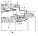
- The invention will be described in more detail with reference to the drawing, in which a portion of a sealing assembly according to the invention is shown arranged on a roller bearing in axial section.
- As shown in the drawing, the sealing assembly comprises a sealing ring 1 and a
closure member 2 cooperating therewith. - The extremity 3 extending along the outer periphery of the sealing ring 1 is fixed in the
outer race 4a of thebearing 4, while theclosure member 2 is connected to theinner race 5 of the bearing. - In the
closure member 2, anannular recess 6 is formed, into which the axially directedextremity 7 extending along the inner periphery of the sealing ring 1 projects with clearance on all sides. The axially directedextremity 7 passes over into a connecting portion 8 generally directed radially, which in turn passes over into an axially directed intermediate portion 9, connected byintermediate portion 10 with extremity 3. The innermost peripheral wall of therecess 6 passes over into a wall portion 11 extending parallel to the connecting portion 8 at a distance, and the said wall portion in turn passes over into awall portion 12 extending parallel to the axial intermediate portion 9 at a distance. - The sealing ring 1 and
closure member 2 enclose achamber 13, in which lubricant is trapped during service. The innermost wall of thechamber 13 is formed by the cylindrical surface 14 of theclosure member 2, so that upon rotation of theinner race 5 and hence of theclosure member 2, a centrifugal force is exerted on the lubricant inside thechamber 13, whereby said lubricant inchamber 13 is spun off outward away from the communication ofchamber 13 with the surroundings, which communication is established by the contoured slit consisting of the clearance all around between the axially extendingportion 7 and therecess 6, the clearance between the connecting portion 8 and the wall portion 11, and the clearance between the axially extending intermediate portion 9 and thewall portion 12. This contoured slit, consisting of portions predominantly extending axially, effectively prevents dirt from entering thechamber 13 from the outside'and thence entering the bearing. - In the innermost peripheral wall of the
recess 6, agroove 15 is arranged, serving as a lubricant reservoir to make up lubricant escaping unavoidably but in extremely small amounts through the slit to the outside, so that effective lubricant inchamber 13 remains wholly inside said chamber for a longer period of time. - Likewise shown are
rollers 16 withcage 17 and the shaft 18 on which theinner race 5 is fixed. - Between the end of the axially projecting
extremity 7 of the sealing ring 1 and the bottom of theannular recess 6, a ring or packing 19 of self-lubricating material may readily be arranged, thereby optimizing the seal, because the frictional resistance is very low.
Claims (5)
Applications Claiming Priority (2)
| Application Number | Priority Date | Filing Date | Title |
|---|---|---|---|
| NL8105701A NL8105701A (en) | 1981-12-17 | 1981-12-17 | SEALING ASSEMBLY FOR A ROLL BEARING. |
| NL8105701 | 1981-12-17 |
Publications (2)
| Publication Number | Publication Date |
|---|---|
| EP0082552A1 true EP0082552A1 (en) | 1983-06-29 |
| EP0082552B1 EP0082552B1 (en) | 1986-11-05 |
Family
ID=19838572
Family Applications (1)
| Application Number | Title | Priority Date | Filing Date |
|---|---|---|---|
| EP82201563A Expired EP0082552B1 (en) | 1981-12-17 | 1982-12-09 | Sealing assembly for a rolling bearing |
Country Status (6)
| Country | Link |
|---|---|
| US (1) | US4438990A (en) |
| EP (1) | EP0082552B1 (en) |
| JP (1) | JPS58109720A (en) |
| CA (1) | CA1215417A (en) |
| DE (1) | DE3274141D1 (en) |
| NL (1) | NL8105701A (en) |
Cited By (3)
| Publication number | Priority date | Publication date | Assignee | Title |
|---|---|---|---|---|
| EP0754873A2 (en) * | 1995-07-21 | 1997-01-22 | SKF INDUSTRIE S.p.A. | A rolling contact bearing sealing device |
| EP0905394A2 (en) * | 1997-09-26 | 1999-03-31 | The Timken Company | Package bearing with retainer |
| FR2790802A1 (en) | 1999-03-10 | 2000-09-15 | Roulements Soc Nouvelle | PREASSEMBLY ASSEMBLY FORMING A MAGNETIC SEAL AND BEARING OR BEARING INCORPORATING SUCH AN ASSEMBLY |
Families Citing this family (8)
| Publication number | Priority date | Publication date | Assignee | Title |
|---|---|---|---|---|
| IT206286Z2 (en) * | 1985-12-10 | 1987-07-20 | Riv Officine Di Villar Perosa | PERFECTLY SEALED COMPLEX PARTICULARLY FOR RAILWAY AXLE BEARINGS |
| JPS62115522U (en) * | 1986-01-16 | 1987-07-22 | ||
| US5975533A (en) * | 1996-09-13 | 1999-11-02 | Brenco, Incorporated | Labyrinth-type seal for railway car journal bearing |
| US7607836B2 (en) * | 2007-03-16 | 2009-10-27 | Amsted Rail Company, Inc | Seal for railway car journal bearing |
| CN102859217B (en) * | 2010-04-08 | 2015-06-03 | Ntn株式会社 | Bearing device for axle of railway vehicle |
| JP5583486B2 (en) * | 2010-06-10 | 2014-09-03 | Ntn株式会社 | Axle bearing device for railway vehicle |
| US8360651B1 (en) * | 2011-09-22 | 2013-01-29 | Amsted Rail Company, Inc. | Roller bearing seal |
| FR2992381B1 (en) * | 2012-06-26 | 2015-02-27 | Skf Ab | ROLLING BODY BEARING AND FLANGE |
Citations (8)
| Publication number | Priority date | Publication date | Assignee | Title |
|---|---|---|---|---|
| US1890839A (en) * | 1929-10-12 | 1932-12-13 | Gen Motors Corp | Seal or guard |
| US1895288A (en) * | 1927-08-24 | 1933-01-24 | Master Electric Co | Bearing mounting |
| GB698729A (en) * | 1952-05-01 | 1953-10-21 | Assar Liljeqvist | Improvements in or relating to shaft bearing lubricant seals |
| FR1148112A (en) * | 1955-03-25 | 1957-12-04 | Napier & Son Ltd | Bearing for rotating shaft |
| FR1383004A (en) * | 1962-10-16 | 1964-12-24 | Bearing seal with one or more sealing discs | |
| DE2037387A1 (en) * | 1969-11-21 | 1971-07-08 | Timken Co | Bearing arrangement with flexible labyrinth seals |
| US3774982A (en) * | 1971-12-02 | 1973-11-27 | Hitachi Ltd | Bearing device for rotary machines |
| GB1524477A (en) * | 1975-10-28 | 1978-09-13 | New River Mfg Co Inc | Labyrinth lubricant seal for belt conveyor roll |
Family Cites Families (5)
| Publication number | Priority date | Publication date | Assignee | Title |
|---|---|---|---|---|
| US1978739A (en) * | 1930-03-08 | 1934-10-30 | Gen Motors Corp | Seal or guard |
| US2210543A (en) * | 1938-03-26 | 1940-08-06 | Timken Roller Bearing Co | End closure for axle housing |
| US3101954A (en) * | 1960-06-15 | 1963-08-27 | Int Harvester Co | Self adjusting seal |
| DE1425177A1 (en) * | 1962-10-16 | 1969-01-02 | Ziller Dr Ing E H Hans | Roller bearing seal with a grinding ring made of rubber or the like. |
| US3527512A (en) * | 1968-09-27 | 1970-09-08 | Eastman Kodak Co | High temperature bearing seal construction |
-
1981
- 1981-12-17 NL NL8105701A patent/NL8105701A/en not_active Application Discontinuation
-
1982
- 1982-12-01 JP JP57211172A patent/JPS58109720A/en active Pending
- 1982-12-02 US US06/446,397 patent/US4438990A/en not_active Expired - Fee Related
- 1982-12-07 CA CA000417169A patent/CA1215417A/en not_active Expired
- 1982-12-09 DE DE8282201563T patent/DE3274141D1/en not_active Expired
- 1982-12-09 EP EP82201563A patent/EP0082552B1/en not_active Expired
Patent Citations (8)
| Publication number | Priority date | Publication date | Assignee | Title |
|---|---|---|---|---|
| US1895288A (en) * | 1927-08-24 | 1933-01-24 | Master Electric Co | Bearing mounting |
| US1890839A (en) * | 1929-10-12 | 1932-12-13 | Gen Motors Corp | Seal or guard |
| GB698729A (en) * | 1952-05-01 | 1953-10-21 | Assar Liljeqvist | Improvements in or relating to shaft bearing lubricant seals |
| FR1148112A (en) * | 1955-03-25 | 1957-12-04 | Napier & Son Ltd | Bearing for rotating shaft |
| FR1383004A (en) * | 1962-10-16 | 1964-12-24 | Bearing seal with one or more sealing discs | |
| DE2037387A1 (en) * | 1969-11-21 | 1971-07-08 | Timken Co | Bearing arrangement with flexible labyrinth seals |
| US3774982A (en) * | 1971-12-02 | 1973-11-27 | Hitachi Ltd | Bearing device for rotary machines |
| GB1524477A (en) * | 1975-10-28 | 1978-09-13 | New River Mfg Co Inc | Labyrinth lubricant seal for belt conveyor roll |
Cited By (6)
| Publication number | Priority date | Publication date | Assignee | Title |
|---|---|---|---|---|
| EP0754873A2 (en) * | 1995-07-21 | 1997-01-22 | SKF INDUSTRIE S.p.A. | A rolling contact bearing sealing device |
| EP0754873A3 (en) * | 1995-07-21 | 1997-09-17 | Skf Ind Spa | A rolling contact bearing sealing device |
| US5890812A (en) * | 1995-07-21 | 1999-04-06 | Skf Industrie S.P.A. | Rolling contact bearing sealing device |
| EP0905394A2 (en) * | 1997-09-26 | 1999-03-31 | The Timken Company | Package bearing with retainer |
| EP0905394A3 (en) * | 1997-09-26 | 2000-05-24 | The Timken Company | Package bearing with retainer |
| FR2790802A1 (en) | 1999-03-10 | 2000-09-15 | Roulements Soc Nouvelle | PREASSEMBLY ASSEMBLY FORMING A MAGNETIC SEAL AND BEARING OR BEARING INCORPORATING SUCH AN ASSEMBLY |
Also Published As
| Publication number | Publication date |
|---|---|
| EP0082552B1 (en) | 1986-11-05 |
| NL8105701A (en) | 1983-07-18 |
| US4438990A (en) | 1984-03-27 |
| JPS58109720A (en) | 1983-06-30 |
| CA1215417A (en) | 1986-12-16 |
| DE3274141D1 (en) | 1986-12-11 |
Similar Documents
| Publication | Publication Date | Title |
|---|---|---|
| US5022659A (en) | Seal assembly for antifriction bearings | |
| EP0202702B1 (en) | Seal for an axle bearing | |
| US5174583A (en) | Unitary bearing seal | |
| US4402515A (en) | Labyrinth seal with contamination trap | |
| US9644681B2 (en) | Low-friction dynamic seal | |
| EP0082552A1 (en) | Sealing assembly for a rolling bearing | |
| JPS6327579B2 (en) | ||
| EP0154424A2 (en) | Unitized wheel bearing seal assembly | |
| US4502739A (en) | Roller bearing seal | |
| US10907689B2 (en) | Heavy duty wheel seal with dry running resistance | |
| US4323289A (en) | Roller bearing having a forcible lubrication function | |
| US4209178A (en) | Lubricant seal | |
| US2445432A (en) | Bearing assembly | |
| US4183127A (en) | Top rollers and method for manufacture thereof | |
| JPH0921396A (en) | Bearing seal device for water pump | |
| US6612583B2 (en) | Bearing seal | |
| JPH0921397A (en) | Bearing seal device for water pump | |
| CA1099307A (en) | Lubricant seal | |
| JP3360355B2 (en) | Bearing device for rotating electric machine | |
| US4676671A (en) | Seals for bearing with circulating outer ring | |
| CN214788627U (en) | Labyrinth seal structure | |
| JPH066693Y2 (en) | Outer rotor type motor shaft seal device | |
| JPH04117213U (en) | Bearing seal structure | |
| WO1999034125A1 (en) | Bearing with grease dosing | |
| EP0392740A2 (en) | Motor bearing assemblies |
Legal Events
| Date | Code | Title | Description |
|---|---|---|---|
| PUAI | Public reference made under article 153(3) epc to a published international application that has entered the european phase |
Free format text: ORIGINAL CODE: 0009012 |
|
| AK | Designated contracting states |
Designated state(s): DE FR GB IT NL |
|
| 17P | Request for examination filed |
Effective date: 19831223 |
|
| GRAA | (expected) grant |
Free format text: ORIGINAL CODE: 0009210 |
|
| AK | Designated contracting states |
Kind code of ref document: B1 Designated state(s): DE FR GB IT NL |
|
| REF | Corresponds to: |
Ref document number: 3274141 Country of ref document: DE Date of ref document: 19861211 |
|
| ET | Fr: translation filed | ||
| ITF | It: translation for a ep patent filed |
Owner name: STUDIO TORTA SOCIETA' SEMPLICE |
|
| PLBE | No opposition filed within time limit |
Free format text: ORIGINAL CODE: 0009261 |
|
| STAA | Information on the status of an ep patent application or granted ep patent |
Free format text: STATUS: NO OPPOSITION FILED WITHIN TIME LIMIT |
|
| 26N | No opposition filed | ||
| ITTA | It: last paid annual fee | ||
| PGFP | Annual fee paid to national office [announced via postgrant information from national office to epo] |
Ref country code: GB Payment date: 19921127 Year of fee payment: 11 |
|
| PGFP | Annual fee paid to national office [announced via postgrant information from national office to epo] |
Ref country code: FR Payment date: 19921209 Year of fee payment: 11 |
|
| PGFP | Annual fee paid to national office [announced via postgrant information from national office to epo] |
Ref country code: DE Payment date: 19921222 Year of fee payment: 11 |
|
| PGFP | Annual fee paid to national office [announced via postgrant information from national office to epo] |
Ref country code: NL Payment date: 19921231 Year of fee payment: 11 |
|
| PG25 | Lapsed in a contracting state [announced via postgrant information from national office to epo] |
Ref country code: GB Effective date: 19931209 |
|
| PG25 | Lapsed in a contracting state [announced via postgrant information from national office to epo] |
Ref country code: NL Effective date: 19940701 |
|
| GBPC | Gb: european patent ceased through non-payment of renewal fee |
Effective date: 19931209 |
|
| NLV4 | Nl: lapsed or anulled due to non-payment of the annual fee | ||
| PG25 | Lapsed in a contracting state [announced via postgrant information from national office to epo] |
Ref country code: FR Effective date: 19940831 |
|
| PG25 | Lapsed in a contracting state [announced via postgrant information from national office to epo] |
Ref country code: DE Effective date: 19940901 |
|
| REG | Reference to a national code |
Ref country code: FR Ref legal event code: ST |