EP0082030A1 - Dispositif automatique de distribution de liquide appliqué notamment à l'irrigation - Google Patents
Dispositif automatique de distribution de liquide appliqué notamment à l'irrigation Download PDFInfo
- Publication number
- EP0082030A1 EP0082030A1 EP82402031A EP82402031A EP0082030A1 EP 0082030 A1 EP0082030 A1 EP 0082030A1 EP 82402031 A EP82402031 A EP 82402031A EP 82402031 A EP82402031 A EP 82402031A EP 0082030 A1 EP0082030 A1 EP 0082030A1
- Authority
- EP
- European Patent Office
- Prior art keywords
- liquid
- container
- irrigation
- automatic device
- filling
- Prior art date
- Legal status (The legal status is an assumption and is not a legal conclusion. Google has not performed a legal analysis and makes no representation as to the accuracy of the status listed.)
- Withdrawn
Links
Images
Classifications
-
- A—HUMAN NECESSITIES
- A01—AGRICULTURE; FORESTRY; ANIMAL HUSBANDRY; HUNTING; TRAPPING; FISHING
- A01G—HORTICULTURE; CULTIVATION OF VEGETABLES, FLOWERS, RICE, FRUIT, VINES, HOPS OR SEAWEED; FORESTRY; WATERING
- A01G25/00—Watering gardens, fields, sports grounds or the like
- A01G25/16—Control of watering
- A01G25/162—Sequential operation
Definitions
- the liquid distillation is carried out by means of namps bridging gutters inside which is provided, pat dilldients mechanical means, a small exchange, manne to obtain a flow very low flow.
- One of the main disadvantages of the life process is the high sensitivity of the drippers to obstruction due to the small size of the orifices and flow conduits.
- the present invention has the object of eliminating this drawback by providing, in addition, a certain number of advantages.
- the invention relates to a device for dispensing liquids in which the ramps are associated in pairs to operate alternately.
- Each pair of namps is ordered by a piston distributor with two positions. One of them coviespond to the filling of a pole while the autie vampe empties and vice-veisa.
- Each necipient comprises of the dispositise and is supplied in such a way that the emptying can only take place after the filling of all the necipients with the same bulb.
- the liquid is discharged by means of blind tubes fixed by simple fitting on the outlet orifices of the containers. These tubes have a certain number of holes each provided with a pouring spout which avoids the runoff of the liquid along the tube in the case where the latter is not perfectly horizontal.
- each flow orifice representing a dripper we see that. each container corresponds to several drippers, which limits the number of containers and therefore the cost of installation.
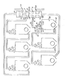
- the invention is better understood If we are looking at the league in which the control distnibuteun 1 composes, an envelope 2 inside which slides a tinoin 3 consisting of four pistons 4, 5, 6 and 7 and which comprises , in outie, a hundred number of oniblces, to know:
- the onibice 8 which is that pan which the liquid annivates under pneesion.
- Olibices 9 and 10 are those which feed each of the two namps respectively.
- Olibices 11 and 12 are lebie air changes.
- the onibices 13 and 14, housed in the end-end glasques show a sliding sheath of the tnioin 3 to the inside of 2.
- the first ramp consists of a pipe 15 which opens at 16 into the lower part of a compartment 17 inside which is placed a ball 18 of density greater than that of the liquid used.
- the upper part 19 forming the ceiling of the compartment 17 comprises, at its axis, an orifice 20 extended towards the outside by a conduit 21 ensuring the flow of the liquid towards its use.
- the orifice 20 forms a sealing seat for the ball 18.
- the upper part of the compartment 11 has another orifice 22 extending outside by a conduit 23 opening to the lower part 24 of the 25 and this lower part 24 is always placed at a higher level with respect to 19 and 20.
- the necipient is provided with a classioue dispositis assuring the evacuation of the groin like, pan example, a ball of tiyak Low density which comes bauchei the tiou formed in the paitie superévieuie 26 Loisqu the iemplillage is dyed.
- This upper part 26 consists of an ovibice 27 which collapses under a 'conduit 28 which feeds the next necipient of the. mania that comes from etoe devotes and so on.
- the liquid thus flows into 23 for supplying the container with the container then, in the same manner, the second then the third, etc.
- a valve placed at the head of the boom allows the filling rate to be adjusted in order to regulate the frequency of dispensing.
- the distvibuteuis being bianché in diversion sui the main pipeline, one can, natwiellement, in disposen a giand nombie. with the coviesponding necipients of maniene to cover the whole of the pan to iviguen.
- each point of annotation develops a quantity six to the intervals of time that it is possible to negate precisely, so that this inten-valle of time does not undergo modifications due to the uaviations of pnession which can follow in the general feeding from the head, one can place xegulateuis of pnession in omont of each distvibuteui.
- the liquid circulates constantly inside a ramp being filled and that the dispenser is constructed to slide under a very slight thrust, the. pressure is always very low. during the filling phase of a ramp. It is practically zero during the emptying phase.
- each of them will be provided, at its lower part, points intended to be stuck in the ground.
- the invention described relates mainly to irrigation by providing a number of new advantages over the traditional system. tional drip.
- Toutgois it can find other applications, in particular for the precise and automatic filling of cans, drums etc ... of different liquids.
- the containers described above will constitute calibrated dispensers emptying into the cans to be filled.
- the standard metering units can be of variable and adjustable capacity. It is possible, for this, to use various known devices such as for example making the standard metering device in two telescopic parts with a system of graduated rule and capacity indicator for each position.
Landscapes
- Engineering & Computer Science (AREA)
- Water Supply & Treatment (AREA)
- Life Sciences & Earth Sciences (AREA)
- Environmental Sciences (AREA)
- Basic Packing Technique (AREA)
- Supply Of Fluid Materials To The Packaging Location (AREA)
Applications Claiming Priority (2)
| Application Number | Priority Date | Filing Date | Title |
|---|---|---|---|
| FR8120720 | 1981-11-05 | ||
| FR8120720A FR2515478A1 (fr) | 1981-11-05 | 1981-11-05 | Dispositif automatique de distribution de liquide applique notamment a l'irrigation |
Publications (1)
| Publication Number | Publication Date |
|---|---|
| EP0082030A1 true EP0082030A1 (fr) | 1983-06-22 |
Family
ID=9263711
Family Applications (1)
| Application Number | Title | Priority Date | Filing Date |
|---|---|---|---|
| EP82402031A Withdrawn EP0082030A1 (fr) | 1981-11-05 | 1982-11-04 | Dispositif automatique de distribution de liquide appliqué notamment à l'irrigation |
Country Status (3)
| Country | Link |
|---|---|
| EP (1) | EP0082030A1 (OSRAM) |
| FR (1) | FR2515478A1 (OSRAM) |
| WO (1) | WO1983001558A1 (OSRAM) |
Families Citing this family (1)
| Publication number | Priority date | Publication date | Assignee | Title |
|---|---|---|---|---|
| US4676023A (en) * | 1985-02-06 | 1987-06-30 | Kei Mori | Cultivation device by use of water-and-air mixture |
Citations (2)
| Publication number | Priority date | Publication date | Assignee | Title |
|---|---|---|---|---|
| US2714388A (en) * | 1950-01-04 | 1955-08-02 | John C F Malthaner | Automatic water distributors |
| US4178954A (en) * | 1977-06-14 | 1979-12-18 | Hal Klieves | Diaphragm valve and valve system |
-
1981
- 1981-11-05 FR FR8120720A patent/FR2515478A1/fr active Granted
-
1982
- 1982-11-04 EP EP82402031A patent/EP0082030A1/fr not_active Withdrawn
- 1982-11-04 WO PCT/FR1982/000179 patent/WO1983001558A1/fr not_active Ceased
Patent Citations (2)
| Publication number | Priority date | Publication date | Assignee | Title |
|---|---|---|---|---|
| US2714388A (en) * | 1950-01-04 | 1955-08-02 | John C F Malthaner | Automatic water distributors |
| US4178954A (en) * | 1977-06-14 | 1979-12-18 | Hal Klieves | Diaphragm valve and valve system |
Also Published As
| Publication number | Publication date |
|---|---|
| WO1983001558A1 (fr) | 1983-05-11 |
| FR2515478A1 (fr) | 1983-05-06 |
| FR2515478B1 (OSRAM) | 1984-05-04 |
Similar Documents
| Publication | Publication Date | Title |
|---|---|---|
| EP1960305B1 (fr) | Remplisseuse comprenant des becs de remplissage equipes de conduits de mise en boucle du corps de bec | |
| EP0082030A1 (fr) | Dispositif automatique de distribution de liquide appliqué notamment à l'irrigation | |
| FR2812859A1 (fr) | Dispositif doseur destine a etre monte ou insere dans le goulot d'un recipient contenant un liquide a derverser en doses | |
| FR2561269A1 (fr) | Dispositif de mouillage de fil et broche de retordage a double torsion equipee de ce dispositif | |
| FR2522041A1 (fr) | Distributeur passif muni d'un dispositif de mise a l'air libre double | |
| WO2021122433A1 (fr) | Bec de remplissage avec canalisation de retour | |
| FR2957533A1 (fr) | Dispositif de dosage et de melange controles de plusieurs substances liquides actives | |
| FR2682554A1 (fr) | Unite integree de systeme de fertilisation et d'irrigation. | |
| US20050183334A1 (en) | Stackable planting containers with capillary watering | |
| FR2543794A1 (fr) | Dispositif autonome d'irrigation | |
| EP1000326B1 (en) | Assembly comprising a flexible container having a dosing device and dosing device of such assembly | |
| FR2599711A1 (fr) | Dispositif de dosage et de distribution pour le conditionnement de produits liquides | |
| FR2579193A1 (fr) | Robinet telescopique pour reservoir de machine automatique de remplissage de liquide | |
| GB2058532A (en) | Introducing liquid into soil or other growth medium | |
| FR2548360A1 (fr) | Dispositif pour le prelevement et la mesure du debit d'un liquide en circulation constante ou pulsee | |
| EP0341149B1 (fr) | Dispositif de compensation par déversement d'un liquide en quantité dosée et son application au réapprovisionnement d'un circuit hydraulique | |
| FR2497059A1 (fr) | Dispositif d'arrosage automatique des plantes en pots ou autres | |
| BE892286A (fr) | Dispositif de commande d'une installation d'irrigation ou d'arrosage | |
| SU1262328A1 (ru) | Установка дл автоматического вз ти раздельных осредненных проб жидкости | |
| EP0756037B1 (fr) | Appareil à tracer des lignes au sol | |
| FR2935369A1 (fr) | Siphon inverse reliant des reservoirs | |
| EP0332539B1 (fr) | Procédé et dispositif pour la distribution gravitaire d'un volume mesuré de produit liquide | |
| FR2541081A1 (fr) | Reservoir d'eau et systemes de regulation de debits pour l'irrigation des plantes cultivees en conteneurs et eventuellement en plein champ | |
| FR2682432A2 (en) | Hydraulic system for forcing liquid at a height by use of hydrostatic thrust (upthrust), and water raising machine | |
| RU1777717C (ru) | Автоматическое поливное устройство |
Legal Events
| Date | Code | Title | Description |
|---|---|---|---|
| PUAI | Public reference made under article 153(3) epc to a published international application that has entered the european phase |
Free format text: ORIGINAL CODE: 0009012 |
|
| AK | Designated contracting states |
Designated state(s): AT BE CH DE FR GB IT LI LU NL SE |
|
| 17P | Request for examination filed |
Effective date: 19831223 |
|
| STAA | Information on the status of an ep patent application or granted ep patent |
Free format text: STATUS: THE APPLICATION IS DEEMED TO BE WITHDRAWN |
|
| 18D | Application deemed to be withdrawn |
Effective date: 19840223 |