EP0082004A2 - Method of producing mailer with self-contained reply envelope - Google Patents
Method of producing mailer with self-contained reply envelope Download PDFInfo
- Publication number
- EP0082004A2 EP0082004A2 EP82306636A EP82306636A EP0082004A2 EP 0082004 A2 EP0082004 A2 EP 0082004A2 EP 82306636 A EP82306636 A EP 82306636A EP 82306636 A EP82306636 A EP 82306636A EP 0082004 A2 EP0082004 A2 EP 0082004A2
- Authority
- EP
- European Patent Office
- Prior art keywords
- envelope
- sheet
- enclosure
- outer envelope
- reply
- Prior art date
- Legal status (The legal status is an assumption and is not a legal conclusion. Google has not performed a legal analysis and makes no representation as to the accuracy of the status listed.)
- Granted
Links
Images


Classifications
-
- B—PERFORMING OPERATIONS; TRANSPORTING
- B42—BOOKBINDING; ALBUMS; FILES; SPECIAL PRINTED MATTER
- B42D—BOOKS; BOOK COVERS; LOOSE LEAVES; PRINTED MATTER CHARACTERISED BY IDENTIFICATION OR SECURITY FEATURES; PRINTED MATTER OF SPECIAL FORMAT OR STYLE NOT OTHERWISE PROVIDED FOR; DEVICES FOR USE THEREWITH AND NOT OTHERWISE PROVIDED FOR; MOVABLE-STRIP WRITING OR READING APPARATUS
- B42D5/00—Sheets united without binding to form pads or blocks
- B42D5/02—Form sets
- B42D5/023—Continuous form sets
- B42D5/025—Mailer assemblies
- B42D5/026—Mailer assemblies with return letter or return card
-
- B—PERFORMING OPERATIONS; TRANSPORTING
- B31—MAKING ARTICLES OF PAPER, CARDBOARD OR MATERIAL WORKED IN A MANNER ANALOGOUS TO PAPER; WORKING PAPER, CARDBOARD OR MATERIAL WORKED IN A MANNER ANALOGOUS TO PAPER
- B31B—MAKING CONTAINERS OF PAPER, CARDBOARD OR MATERIAL WORKED IN A MANNER ANALOGOUS TO PAPER
- B31B2150/00—Flexible containers made from sheets or blanks, e.g. from flattened tubes
-
- B—PERFORMING OPERATIONS; TRANSPORTING
- B31—MAKING ARTICLES OF PAPER, CARDBOARD OR MATERIAL WORKED IN A MANNER ANALOGOUS TO PAPER; WORKING PAPER, CARDBOARD OR MATERIAL WORKED IN A MANNER ANALOGOUS TO PAPER
- B31B—MAKING CONTAINERS OF PAPER, CARDBOARD OR MATERIAL WORKED IN A MANNER ANALOGOUS TO PAPER
- B31B2160/00—Shape of flexible containers
- B31B2160/10—Shape of flexible containers rectangular and flat, i.e. without structural provision for thickness of contents
-
- B—PERFORMING OPERATIONS; TRANSPORTING
- B31—MAKING ARTICLES OF PAPER, CARDBOARD OR MATERIAL WORKED IN A MANNER ANALOGOUS TO PAPER; WORKING PAPER, CARDBOARD OR MATERIAL WORKED IN A MANNER ANALOGOUS TO PAPER
- B31B—MAKING CONTAINERS OF PAPER, CARDBOARD OR MATERIAL WORKED IN A MANNER ANALOGOUS TO PAPER
- B31B2170/00—Construction of flexible containers
- B31B2170/20—Construction of flexible containers having multi-layered walls, e.g. laminated or lined
-
- Y—GENERAL TAGGING OF NEW TECHNOLOGICAL DEVELOPMENTS; GENERAL TAGGING OF CROSS-SECTIONAL TECHNOLOGIES SPANNING OVER SEVERAL SECTIONS OF THE IPC; TECHNICAL SUBJECTS COVERED BY FORMER USPC CROSS-REFERENCE ART COLLECTIONS [XRACs] AND DIGESTS
- Y10—TECHNICAL SUBJECTS COVERED BY FORMER USPC
- Y10S—TECHNICAL SUBJECTS COVERED BY FORMER USPC CROSS-REFERENCE ART COLLECTIONS [XRACs] AND DIGESTS
- Y10S493/00—Manufacturing container or tube from paper; or other manufacturing from a sheet or web
- Y10S493/916—Pliable container
- Y10S493/917—Envelope
- Y10S493/921—Envelope having integrally formed insert
Definitions
- This invention relates to the manufacture of articles suitable for mailing comprising an outer envelope containing at least one pre-printed enclosure and a pre-formed return envelope, one or more of which can be personalized.
- the method described herein is particularly suited for commercial production of articles such as advertisements, solicitations, billings and the like, in which the printed contents is for the most part the same, and tens of thousands, or even millions of articles must be mailed. Such mailings often include a return envelope to encourage a favorable and prompt reply.
- a mailed article is personalized when information more or less unique to the intended recipient is printed on the article and/or on its enclosures.
- the information that can be personalized includes the recipient's name, address, sex, age, account or billing number, and other data.
- the information can be represented by either alpha-numeric characters or indicia particularly adapted to be read by electronic character recognition devices, such as bar codes and the like.
- the present invention relates to a method for producing an article suitable for mailing, comprising an outer envelope containing at least one enclosure and a separate reply envelope formed during manufacture of the article, rather than being inserted subsequently.
- the method produces a preformed and completely made-up reply envelope simultaneously with the preparation of the outer envelope and enclosures.
- the flap of the reply envelope can be provided with remoistenable gum and, in a preferred embodiment, a response device is detachably connected to the flap along a line of perforations.
- Personalization can be provided on the outer envelope, the enclosure or letter sheets, and on the reply envelope and response device.
- the invention allows a variety of enclosures to be formed in the manufacture of the article.
- the present invention comprises a number of steps.
- the first step is to mate in a superposed, aligned configuration a first composite sheet with a second composite sheet.
- the first composite sheet consists of an outer envelope sheet defining a flap, a front panel and a rear panel, and integral therewith a first enclosure sheet joined along a transverse line to the rear panel.
- the second composite sheet consists of a second enclosure sheet, and integral therewith a reply envelope sheet defining a flap, a front panel and a rear panel, the reply envelope sheet being joined along a transverse line to the second enclosure sheet.
- a response device is positioned between the second enclosure sheet and the reply envelope sheet, one transverse line of perforations joining the response device to the second enclosure sheet, and another transverse line of perforations joining the reply envelope sheet to the response device.
- the composite sheets are folded so as to superpose the reply envelope rear panel in alignment with the reply envelope front panel.
- the longitudinal edges of the front and rear reply envelope panels then are bonded to form a reply envelope pocket.
- the composite sheets are further folded to position the reply envelope, first enclosure sheet, second enclosure sheet, and optionally, the response device, between the front and rear panels of the outer envelope sheet.
- the longitudinal edges of the outer envelope front and rear panels are next bonded to form an outer envelope pocket containing the reply envelope, the first and second enclosure sheets, and, optionally, the response device.
- a separating step simultaneously separates the first enclosure sheet from the outer envelope rear panel, and the second enclosure sheet from the reply envelope, or, if used, from the response device.
- the resulting article comprises an outer envelope containing a separate first and second enclosure sheet, a separate reply envelope, and optionally, a response device detachably joined to the reply envelope.
- the method can be adapted to provide additional separate enclosure sheets with the outer envelope. It is also possible to eliminate enclosure sheets entirely, the only enclosure then being a response device along with the reply envelope.
- the method described is particularly advantageous for preparing large numbers of enclosures and reply envelopes, each of which is imprinted with one or more personalized messages.
- the method described herein substantially eliminates the mismatching of the personalized enclosures and reply envelope.
- a personalized reply envelope is particularly advantageous for use in periodic billing. It is not uncommon for organizations that perform periodic billing to request customers to write their billing or account number on the reply envelope. It is also not uncommon for such customers to fail to do so. Consequently, having the customer or account number already entered on the reply envelope greatly improves record keeping. Efficiency results, since the customer or account number will be printed in a uniform, clear manner which can be machine readable. It also eliminates the problem which arises when a customer encloses a check but neglects to return the statement, paper or card containing information identifying him. Because the reply envelope can contain personalized information, identification is assured.
- FIG. 1B there is shown web 10B which is likewise divided by perforated transverse cutting and folding lines 11' into repeating composite sheets 22.
- Webs 10A and 10B are continuous web-forms having line holes 14 that are engaged by a computer directed printer. This permits high speed feeding and proper indexing of the forms for insertion of the personalized messages, and facilitates the bursting operation described below. Webs 10A and 10B are also optionally provided with perforated folding lines 13 and 13', respectively, to facilitate fan folding.
- the composite sheet 12 contains an outer envelope sheet 15 defining a flap 16, to which a remoistenable gum adhesive 17 can be applied.
- Composite sheet 13 also contains an outer envelope front panel 18, an outer envelope rear panel 19 and a first enclosure sheet 20.
- Outer envelope sheet 15 and enclosure sheet 20 are integral, being joined along transverse perforated folding line 13.
- composite sheet 22 contains a second enclosure sheet 23, a response device 35 joined along transverse line 13' to second enclosure sheet 23, and a reply envelope sheet 40 joined along a transverse line of perforations 38 to response device 35.
- the reply envelope sheet 40 defines a reply envelope flap 39, a reply envelope front panel 36 and a reply envelope rear panel 37. Remoistenable gum adhesive 34 can be applied to flap 39.
- the distance between the longitudinal edges of reply envelope sheet 40 is equal to that of sheets 15 and 20.
- Envelope sheet 15 and second enclosure sheet 23 on respective webs 10A and 10B are the same length.
- first enclosure sheet 20 is the same length as-the aggregate length of reply envelope sheet 40 and response device 35.
- blank web 10A is fed into a form printer, such as a flexigraphic, lithographic, gravure or letter press. Each of these presses can print, for example, a form letter appropriately positioned to correspond to the field of first enclosure sheet 20 on web 10A.
- a form printer which can print the fields of second enclosure sheet 23 and response device 35.
- This form printer also prints the reply mailing address on reply envelope front panel 36 and optionally a return postage mailing permit and any form message which the sender desires to have within the fields of reply envelope front panel 36 or rear panel 37. Both sides of sheets 20, 23 and response device 35 can be printed, if desired.
- portion 46 can be die-cut and removed by the form printer.
- the transverse width of portion 46 determines the transverse width of response device 35.
- each portion 45 having substantially the configuration shown in Figure lA, can also be die-cut and removed by the form printer. Their removal lessens the chance of a subsequent trimming operation, described below, leaving unsightly notches in envelope rear panel 19.
- Triangular portions 44 can also be removed by the form printer to provide the desired tapering configuration to the envelope flap 16.
- the shoulder 47, between response device 35 and flap 39, can also be die-cut on the printer to facilitate subsequent bursting steps described below.
- the continuous webs exiting from the form printers are next indexed and fed into computer directed printers for personalization.
- panel 18 of envelope sheet 15 will be printed with the name and address of the recipient.
- first enclosure sheet 20 is in a letter format
- the name and address can be entered and a personal salutation printed, along with any other desired personal data references in the body of the letter.
- Second enclosure sheet 23 may similarly be personalized, with further personal data references in the body of the letter.
- Response device 35 can also advantageously be personalized, as by printing the recipient's name and address to indicate acceptance of a solicitation contained on enclosure sheets 20 and 23.
- the recipient's reply address can be entered either on reply envelope front panel 36 or flap 39. It is also possible to include a unique customer or account number, or other personalized information.
- beads or spots 25 of liquid adhesive or hot melt adhesive are applied just inside the opposite longitudinal edges of either enclosure sheet 20 or reply envelope sheet 40.
- the position of these beads or spots 25 are shown in Figure 1B.
- beads or spots 25 can be applied to a more limited area of either sheets 20 or 40. For example, it is satisfactory to apply spots 25 only to the lower left portion of reply envelope rear panel 37.
- webs 10A and 10B are brought into an aligned superposed configuration for mating. They are then pressed together so that they are joined and bonded by means of the adhesive beads or spots 25.
- bonding can be accomplished by passing composite sheets 12 and 22 through crimping wheels or other crimping means which are known in the art.
- Composite sheets 12 and 22 remain joined together during subsequent steps and through one of the folding operations.
- the joining of composite sheets 12 and 22 together entirely eliminates any risk of a subsequent mismatching and its attendant waste, and reduces greatly the need for quality control checks on the finished product.
- this method of joining composite sheets 12 and 22 substantially eliminates shifting and misalignment during the high speed folding process.
- Mating and glued webs 10A and 10B are next subject to a line hole slitting and removal operation that occurs on a burster. Specifically, those portions of composite sheet 22 lying outside the field of envelope sheet 15 and first enclosure sheet 20 are removed. In a similar manner, those portions of composite sheet 22 which lie outside the fields of second enclosure sheet 23, response device 35 and reply envelope sheet 40 are removed.
- Line hole slitting and removal preferably is accomplished by appropriately positioned slitting apparatus that makes the necessary longitudinal cuts.
- the longitudinal edge portions of webs 10A and 10B, which contain the line holes, are then removed.
- Figure 2 illustrates, in an exploded perspective view, sections of webs 10A and 10B, comprising adjacent composite sheets following the line hole cutting and removal operation and prior to bursting.
- the burster also separates, or "bursts," the mated sheets along transverse cutting lines 11 and 11'.
- a bead of adhesive 42 is applied inwardly of each opposite longitudinal edge of either reply envelope front panel 36 or rear panel 37. It is preferable to apply adhesive inwardly of the edges of reply envelope front panel 36, as shown in Figure 1B.
- reply envelope rear panel 37 is folded towards reply envelope front panel 36 along transverse fold line 30.
- This folding step is shown in Figure 3.
- the position of fold line 30 is somewhat less than one third of the distance between, on the first part, the free ends of first enclosure sheet 20 and reply envelope rear panel 37, and, on the second part, perforated folding lines 13 and 13'.
- This fold line position is preferred since it prevents further folding in a subsequent folding step of the free ends of first enclosure sheet 20 and reply envelope rear panel 37, as illustrated in Figure 5.
- reply envelope rear panel 37 Upon folding, reply envelope rear panel 37 is superposed and brought into overlying alignment with reply envelope front panel 36. Pressure is then applied to seal the opposite edges to form a reply envelope pocket.
- Figures 4 through 6 show reply envelope front and rear panels 36 and 37 as separate panels, even though they are sealed to form a reply envelope pocket, so that the structure produced by the present method can be described with clarity.
- mated and joined composite sheets 12 and 22 are next folded along a second transverse fold line corresponding to perforated fold lines 13 and 13', respectively.
- the opposite longitudinal edges of first enclosure sheet 20, and the reply envelope pocket made from reply envelope front panel 36 and rear panel 37 are trimmed off, as by a cutting wheel.
- the transverse width of the reply envelope pocket is approximately equal to that of second enclosure sheet 23. Since adhesive beads 42 were applied inwardly of the edges that were trimmed, the reply envelope pocket remains intact subsequent to trimming.
- the foregoing trimming operation completely removes those portions of the sheets that were glued together to hold the sheets in a mated aligned superposed configuration.
- no undesirable shifting or misalignment during subsequent processing results, because the two previous folds result in composite sheets 12 and 22 being in a folded and securely nested configuration.
- beads of adhesive are applied along the opposite longitudinal edges of the inside of either outer envelope front or rear panel 18 or 19, and the panel edges are brought into overlying alignment and pressure is applied to seal the opposite edges to form the outer envelope pocket containing the various enclosures. It is preferred that the adhesive be applied to the opposite edges 32 of outer envelope front panel 18, as illustrated in Figure lA.
- the folded first enclosure sheet 20 is separated from the outer envelope rear panel 19 along line 13 and second enclosure sheet 23 is separated from response device 35 along line 13'.
- These separation operations can advantageously be combined into a single step with the final trimming of the exposed edges that appear behind the front panel of the envelope sheet.
- any portion of second enclosure sheet 23 which overlaps flap 16 should be removed so that the finished envelope can be sealed.
- a slitting device comprising scissor slitting wheels, is adjusted to the thickness of the paper stock to trim cleanly away the following: both ends of second enclosure sheet 23; portions of first enclosure sheet 20 and outer envelope rear panel 19 lying adjacent to fold line 13; and the portion of response device 35 lying adjacent to fold line 13'.
- the paper to be trimmed is made accessible to the slitting device by means of a flap deflector 50, which temporarily bends down outer envelope flap 16.
- the edges of the above-identified materials can then be passed into slitting wheels 55.
- Figure 6, is a cutaway sectional view showing the enclosures and upper edge of rear envelope panel 19 being engaged by cutting wheels 55, while flap 16 is held out of the way by flap deflector 50.
- this particular embodiment of the method of this invention results in a personalized envelope containing two separate enclosure sheets in a nested configuration with a preformed reply envelope, to which is detachably connected a response device.
- FIG. 1C there is shown a third web 10C which is divided by perforated cutting lines 11" into repeating composite sheets 62.
- Composite sheet 62 contains a third enclosure sheet 70 and a fourth enclosure sheet 80.
- Perforated folding lines 13" are again preferably provided to facilitate fan folding.
- third enclosure sheet 70 are positioned inside the longitudinal edges of fourth enclosure sheet 80.
- fourth enclosure sheet 80 The distance between the longitudinal edges of fourth enclosure sheet 80 is equal to that of first enclosure sheet 20 and outer envelope rear panel 19.
- web 10C can be aligned in a superposed configuration between webs 10A and 10B so that response device 35 and reply envelope sheet 40 are over fourth enclosure sheet 80, which in turn is over first enclosure sheet 20, and second enclosure sheet 23 is over third enclosure.sheet 70 which in turn is over envelope sheet 15.
- the three webs 10A, 10B, and 10C can be moved as a unit.
- the method of fabrication described above for two webs is substantially identical to the method used for three webs.
- the only additional necessary step is the application of beads or spots of adhesive 85 to fourth enclosure sheet 80 at a position just inside of its opposite longitudinal edges prior to bringing the webs together in an aligned and mated configuration. After the webs are joined and bonded together, subsequent processing is identical to that employed with two webs only.
- FIG. 1D shows web 10D, wherein the longitudinal dimensions of flap 39, reply envelope front panel 36 and reply envelope rear panel 37 are increased so that response device 35 is eliminated.
- Web 10D can be used according to the methods described above. Web 10D can also be used in combination with web 10C to provide additional enclosure sheets as desired.
- FIG. lE Yet another embodiment of the present invention is shown in Figure lE.
- response device 35 is joined along transverse line 13 to outer envelope rear panel 19, and reply envelope 40 is joined along transverse line of perforations 38 to response device 35.
- composite sheet 12 comprises outer envelope panel 15, response device 35 and reply envelope panel 40.
- This embodiment results in a personalized outer envelope containing a response device detachably connected to a preformed reply envelope. It is useful where the response device satisfactorily serves to contain both the sender's message and the recipient's reply, such that other enclosures would prove unnecessary.
- a second composite sheet is not used with the embodiment shown in Figure lE. Nonetheless, the folding and gluing steps illustrated in and associated with Figures 3 through 5 are equally applicable to the embodiment of Figure lE.
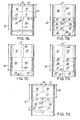
- Figures 7A, 7B, 7C, 7D and 7E typical parallel composite sheets, each of which comprises a line hole punch paper web containing in parallel configuration, pairs of sheets corresponding respectively to those shown in Figures 1A, 1B, 1C, 1D and 1E.
- the parts of Figure 7 correspond to those of Figure 1.
Abstract
Description
- This invention relates to the manufacture of articles suitable for mailing comprising an outer envelope containing at least one pre-printed enclosure and a pre-formed return envelope, one or more of which can be personalized.
- The method described herein is particularly suited for commercial production of articles such as advertisements, solicitations, billings and the like, in which the printed contents is for the most part the same, and tens of thousands, or even millions of articles must be mailed. Such mailings often include a return envelope to encourage a favorable and prompt reply.
- Large volume mailings of this type are often "personalized." A mailed article is personalized when information more or less unique to the intended recipient is printed on the article and/or on its enclosures. The information that can be personalized includes the recipient's name, address, sex, age, account or billing number, and other data. The information can be represented by either alpha-numeric characters or indicia particularly adapted to be read by electronic character recognition devices, such as bar codes and the like.
- This invention is a further improvement over the method previously.disclosed and claimed in U.S. Patent 4,067,171, issued January 10, 1978. That patent describes a method for preparing an envelope containing a plurality of enclosure sheets. Also pertinent is the disclosure of U.S. Patent No. 3,557,519 issued January 29, 1971, which describes a method for making, from an envelope sheet integral with a letter sheet, an addressed envelope containing a single personalized letter. The methods disclosed in both these patents permit large volume mailings of personalized articles while eliminating the possibility of mismatching.
- The teachings and disclosures of both U.S. Patents 3,557,519 and 4,067,171 are incorporated herein by reference. In the practice of the inventions claimed in the above patents, as well as other methods known to the prior art for preparing mailers, if a reply envelope was to be enclosed in the mailer it was necessary to insert the reply envelope into the outer envelope as a separate step before sealing. The reply envelope could only be personalized at the risk of mismatching the personalized information printed on the reply envelope with the other items mailed.
- The present invention relates to a method for producing an article suitable for mailing, comprising an outer envelope containing at least one enclosure and a separate reply envelope formed during manufacture of the article, rather than being inserted subsequently. The method produces a preformed and completely made-up reply envelope simultaneously with the preparation of the outer envelope and enclosures. The flap of the reply envelope can be provided with remoistenable gum and, in a preferred embodiment, a response device is detachably connected to the flap along a line of perforations. Personalization can be provided on the outer envelope, the enclosure or letter sheets, and on the reply envelope and response device. The invention allows a variety of enclosures to be formed in the manufacture of the article.
- The present invention comprises a number of steps. In practicing one method of the present invention, the first step is to mate in a superposed, aligned configuration a first composite sheet with a second composite sheet. The first composite sheet consists of an outer envelope sheet defining a flap, a front panel and a rear panel, and integral therewith a first enclosure sheet joined along a transverse line to the rear panel. The second composite sheet consists of a second enclosure sheet, and integral therewith a reply envelope sheet defining a flap, a front panel and a rear panel, the reply envelope sheet being joined along a transverse line to the second enclosure sheet. In a preferred embodiment of the present invention, a response device is positioned between the second enclosure sheet and the reply envelope sheet, one transverse line of perforations joining the response device to the second enclosure sheet, and another transverse line of perforations joining the reply envelope sheet to the response device.
- After mating, the composite sheets are folded so as to superpose the reply envelope rear panel in alignment with the reply envelope front panel. The longitudinal edges of the front and rear reply envelope panels then are bonded to form a reply envelope pocket. In the next step, the composite sheets are further folded to position the reply envelope, first enclosure sheet, second enclosure sheet, and optionally, the response device, between the front and rear panels of the outer envelope sheet. The longitudinal edges of the outer envelope front and rear panels are next bonded to form an outer envelope pocket containing the reply envelope, the first and second enclosure sheets, and, optionally, the response device. Finally, while the outer envelope flap remains open, a separating step simultaneously separates the first enclosure sheet from the outer envelope rear panel, and the second enclosure sheet from the reply envelope, or, if used, from the response device. Following the method described, the resulting article comprises an outer envelope containing a separate first and second enclosure sheet, a separate reply envelope, and optionally, a response device detachably joined to the reply envelope.
- In another embodiment of the present invention, the method can be adapted to provide additional separate enclosure sheets with the outer envelope. It is also possible to eliminate enclosure sheets entirely, the only enclosure then being a response device along with the reply envelope.
- The method described is particularly advantageous for preparing large numbers of enclosures and reply envelopes, each of which is imprinted with one or more personalized messages. The method described herein substantially eliminates the mismatching of the personalized enclosures and reply envelope.
- The use of personalized enclosures in connection with commercial solicitations is believed to improve the likelihood of obtaining a favorable response from the recipient. The method described herein further improves the likelihood of obtaining a favorable response, because the recipient need not spend the time to enter his return address on the enclosed reply envelope.
- A personalized reply envelope is particularly advantageous for use in periodic billing. It is not uncommon for organizations that perform periodic billing to request customers to write their billing or account number on the reply envelope. It is also not uncommon for such customers to fail to do so. Consequently, having the customer or account number already entered on the reply envelope greatly improves record keeping. Efficiency results, since the customer or account number will be printed in a uniform, clear manner which can be machine readable. It also eliminates the problem which arises when a customer encloses a check but neglects to return the statement, paper or card containing information identifying him. Because the reply envelope can contain personalized information, identification is assured.
- Production of an article by the method described herein allows information to be gathered that was previously unavailable. Because the personalized information printed on the reply envelope is of a uniform character, it is possible to read such information with presently available optical character readers and like equipment. Thus, upon receipt of the reply envelope, the transmitting organization can instantly record the fact that a particular recipient has replied. This is particularly important to organizations such as book clubs, which periodically send items to subscribers or customers who reply only when they do not desire the item, or desire a different item. Accordingly, no unwanted item will be inadvertently sent because of the inevitable time lag between receipt of the reply envelope and examination of its contents.
- The methods described herein can be readily adapted to produce articles in a variety of sizes and formats which are within the capabilities of commercial lithographic and computer directed printers, and the folding and converting equipment which is available in the art.
- Additional specific uses and advantages of the various formats which can be embodied in the methods-of the invention herein will be apparent to those familiar with the art in view of the teachings of this specification.
-
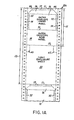
- Figure 1A is a plan view showing a section of continuous paper web containing an outer envelope and first enclosure sheet.
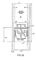
- Figure 1B is a plan view showing a section of continuous paper web containing a second enclosure sheet, response device and reply envelope sheet.
- Figure 1C is a plan view showing a section of continuous paper web containing additional enclosure sheets.
- Figure 1D is a plan view showing a section of continuous paper web containing a second enclosure sheet and reply envelope only.
- Figure lE is a plan view showing a section of continuous paper web containing an outer envelope sheet, a response device and a reply envelope sheet.
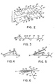
- Figure 2 is a side exploded perspective view illustrating the alignment for mating of two of the partially processed composite sheets from the continuous webs of Figures 1A and 1B.
- Figure 3 is a schematic side view showing the first folding step partially completed on the aligned and joined integral outer envelope and first enclosure sheets and integral second enclosure sheet, response device and reply envelope sheet after die-cutting and bursting from the continuous paper web.
- Figure 4 is a schematic side view of the elements shown in Figure 3, illustrating the partially completed second folding step.
- Figure 5 is a schematic side view of the elements shown in Figure 4, illustrating the partially complete third folding step.
- Figure 6 is a cutaway, sectional schematic side view showing the steps of simultaneously separating and trimming the enclosures and the top edge of the rear envelope panel.
- Figure 7A is a plan view showing a section of continuous paper web containing two outer envelope and first enclosure sheets in parallel configuration.
- Figure 7B is a plan view showing a section of continuous paper web containing, in parallel configuration, pairs of second enclosure sheets, response devices, and reply envelope sheets.
- Figure 7C is a plan view showing a section of continuous paper web containing a pair of additional enclosure sheets in parallel configuration.
- Figure 7D is a plan view showing a section of continuous paper web containing, in parallel configuration, pairs of second enclosure sheets and reply envelope sheets.
- Figure 7E is a plan view showing a section of continuous paper web containing, in parallel configuration, pairs of outer envelope sheets, response devices, and reply envelope sheets.
- Referring to the drawings in detail wherein like reference characters designate corresponding parts throughout the several Figures, and particularly to Figure lA, there is shown
web 10A which is divided by perforatedtransverse cutting lines 11 into repeatingcomposite sheets 12. - In Figure 1B, there is shown web 10B which is likewise divided by perforated transverse cutting and folding lines 11' into repeating
composite sheets 22. -
Webs 10A and 10B are continuous web-forms having line holes 14 that are engaged by a computer directed printer. This permits high speed feeding and proper indexing of the forms for insertion of the personalized messages, and facilitates the bursting operation described below.Webs 10A and 10B are also optionally provided withperforated folding lines 13 and 13', respectively, to facilitate fan folding. - As shown in Figure lA, the
composite sheet 12 contains anouter envelope sheet 15 defining aflap 16, to which a remoistenable gum adhesive 17 can be applied.Composite sheet 13 also contains an outerenvelope front panel 18, an outer enveloperear panel 19 and afirst enclosure sheet 20.Outer envelope sheet 15 andenclosure sheet 20 are integral, being joined along transverseperforated folding line 13. - As shown in Figure 1B,
composite sheet 22 contains asecond enclosure sheet 23, aresponse device 35 joined along transverse line 13' tosecond enclosure sheet 23, and areply envelope sheet 40 joined along a transverse line ofperforations 38 toresponse device 35. Thereply envelope sheet 40 defines areply envelope flap 39, a replyenvelope front panel 36 and a reply enveloperear panel 37. Remoistenable gum adhesive 34 can be applied toflap 39. - Referring to the embodiments illustrated in Figures lA and 1B, the distance between the longitudinal edges of
reply envelope sheet 40 is equal to that ofsheets Envelope sheet 15 andsecond enclosure sheet 23 onrespective webs 10A and 10B are the same length. Likewise,first enclosure sheet 20 is the same length as-the aggregate length ofreply envelope sheet 40 andresponse device 35. Thus, by properly indexing thepre-printed webs 10A and 10B, as by use of the line holes 14, thecomposite sheets response device 35 andreply envelope sheet 40 overfirst enclosure sheet 20, andsecond enclosure sheet 23 overouter envelope sheet 15. Whensheets - In practicing this invention,
blank web 10A is fed into a form printer, such as a flexigraphic, lithographic, gravure or letter press. Each of these presses can print, for example, a form letter appropriately positioned to correspond to the field offirst enclosure sheet 20 onweb 10A. In a similar fashion, web 10B is fed into a form printer which can print the fields ofsecond enclosure sheet 23 andresponse device 35. This form printer also prints the reply mailing address on replyenvelope front panel 36 and optionally a return postage mailing permit and any form message which the sender desires to have within the fields of replyenvelope front panel 36 orrear panel 37. Both sides ofsheets response device 35 can be printed, if desired. - Referring to Figure 1B,
portion 46 can be die-cut and removed by the form printer. The transverse width ofportion 46 determines the transverse width ofresponse device 35. - Likewise, each
portion 45, having substantially the configuration shown in Figure lA, can also be die-cut and removed by the form printer. Their removal lessens the chance of a subsequent trimming operation, described below, leaving unsightly notches in enveloperear panel 19.Triangular portions 44 can also be removed by the form printer to provide the desired tapering configuration to theenvelope flap 16. Theshoulder 47, betweenresponse device 35 andflap 39, can also be die-cut on the printer to facilitate subsequent bursting steps described below. - The continuous webs exiting from the form printers are next indexed and fed into computer directed printers for personalization. Conventionally,
panel 18 ofenvelope sheet 15 will be printed with the name and address of the recipient. Iffirst enclosure sheet 20 is in a letter format, the name and address can be entered and a personal salutation printed, along with any other desired personal data references in the body of the letter.Second enclosure sheet 23 may similarly be personalized, with further personal data references in the body of the letter.Response device 35 can also advantageously be personalized, as by printing the recipient's name and address to indicate acceptance of a solicitation contained onenclosure sheets envelope front panel 36 orflap 39. It is also possible to include a unique customer or account number, or other personalized information. - After
webs 10A and 10B exit the computer directed printers, beads orspots 25 of liquid adhesive or hot melt adhesive are applied just inside the opposite longitudinal edges of eitherenclosure sheet 20 orreply envelope sheet 40. The position of these beads orspots 25 are shown in Figure 1B. Alternatively, beads orspots 25 can be applied to a more limited area of eithersheets spots 25 only to the lower left portion of reply enveloperear panel 37. - After application of the adhesive,
webs 10A and 10B are brought into an aligned superposed configuration for mating. They are then pressed together so that they are joined and bonded by means of the adhesive beads or spots 25. Alternatively, instead of using a separately applied adhesive, bonding can be accomplished by passingcomposite sheets -
Composite sheets composite sheets composite sheets - Mating and glued
webs 10A and 10B are next subject to a line hole slitting and removal operation that occurs on a burster. Specifically, those portions ofcomposite sheet 22 lying outside the field ofenvelope sheet 15 andfirst enclosure sheet 20 are removed. In a similar manner, those portions ofcomposite sheet 22 which lie outside the fields ofsecond enclosure sheet 23,response device 35 andreply envelope sheet 40 are removed. - Line hole slitting and removal preferably is accomplished by appropriately positioned slitting apparatus that makes the necessary longitudinal cuts. The longitudinal edge portions of
webs 10A and 10B, which contain the line holes, are then removed. Figure 2 illustrates, in an exploded perspective view, sections ofwebs 10A and 10B, comprising adjacent composite sheets following the line hole cutting and removal operation and prior to bursting. - The burster also separates, or "bursts," the mated sheets along
transverse cutting lines 11 and 11'. - Following bursting, the individual
composite sheets spots 25, are fed into a conventional multiplate folding machine where three transverse folds are to be made. The sequence and direction of the folds are illustrated in Figures 3, 4 and 5. - Prior to making the first fold, a bead of adhesive 42 is applied inwardly of each opposite longitudinal edge of either reply
envelope front panel 36 orrear panel 37. It is preferable to apply adhesive inwardly of the edges of replyenvelope front panel 36, as shown in Figure 1B. - After application of adhesive, reply envelope
rear panel 37 is folded towards replyenvelope front panel 36 alongtransverse fold line 30. This folding step is shown in Figure 3. In the embodiment of Figure 3, the position offold line 30 is somewhat less than one third of the distance between, on the first part, the free ends offirst enclosure sheet 20 and reply enveloperear panel 37, and, on the second part,perforated folding lines 13 and 13'. This fold line position is preferred since it prevents further folding in a subsequent folding step of the free ends offirst enclosure sheet 20 and reply enveloperear panel 37, as illustrated in Figure 5. - Present United States Postal Service regulations constrain to some degree the position of
fold line 30, since an envelope must be a certain minimum size before it will be accepted for delivery. The distance betweenfolding line 41 andfolding line 30 should be selected in order to comply with such regulations. Subject to this constraint, suitable positions for foldingline 30 will be apparent to one skilled in the art after reading the description of this specification. - Upon folding, reply envelope
rear panel 37 is superposed and brought into overlying alignment with replyenvelope front panel 36. Pressure is then applied to seal the opposite edges to form a reply envelope pocket. For illustrative purposes only, Figures 4 through 6 show reply envelope front andrear panels - As shown in Figure 4, mated and joined
composite sheets perforated fold lines 13 and 13', respectively. As this second fold is made, the opposite longitudinal edges offirst enclosure sheet 20, and the reply envelope pocket made from replyenvelope front panel 36 andrear panel 37 are trimmed off, as by a cutting wheel. As a result of this trimming operation, the transverse width of the reply envelope pocket is approximately equal to that ofsecond enclosure sheet 23. Sinceadhesive beads 42 were applied inwardly of the edges that were trimmed, the reply envelope pocket remains intact subsequent to trimming. - As will be understood with reference to the above description, the foregoing trimming operation completely removes those portions of the sheets that were glued together to hold the sheets in a mated aligned superposed configuration. However, no undesirable shifting or misalignment during subsequent processing results, because the two previous folds result in
composite sheets - As will be appreciated by one familiar with the apparatus employed in the art, the various steps described above can be combined or rearranged in order to accommodate the format of the composite sheets and the capabilities of the equipment available.
- In the next step, beads of adhesive are applied along the opposite longitudinal edges of the inside of either outer envelope front or
rear panel opposite edges 32 of outerenvelope front panel 18, as illustrated in Figure lA. - In the final step, the folded
first enclosure sheet 20 is separated from the outer enveloperear panel 19 alongline 13 andsecond enclosure sheet 23 is separated fromresponse device 35 along line 13'. These separation operations can advantageously be combined into a single step with the final trimming of the exposed edges that appear behind the front panel of the envelope sheet. In this cutting step, any portion ofsecond enclosure sheet 23 which overlapsflap 16 should be removed so that the finished envelope can be sealed. Thus a slitting device, comprising scissor slitting wheels, is adjusted to the thickness of the paper stock to trim cleanly away the following: both ends ofsecond enclosure sheet 23; portions offirst enclosure sheet 20 and outer enveloperear panel 19 lying adjacent to foldline 13; and the portion ofresponse device 35 lying adjacent to fold line 13'. The paper to be trimmed is made accessible to the slitting device by means of aflap deflector 50, which temporarily bends downouter envelope flap 16. The edges of the above-identified materials can then be passed into slittingwheels 55. This step is illustrated in Figure 6, which is a cutaway sectional view showing the enclosures and upper edge ofrear envelope panel 19 being engaged by cuttingwheels 55, whileflap 16 is held out of the way byflap deflector 50. - As a result of the final separation or trimming, this particular embodiment of the method of this invention results in a personalized envelope containing two separate enclosure sheets in a nested configuration with a preformed reply envelope, to which is detachably connected a response device.
- It is also possible to provide additional enclosure sheets. Referring to Figure 1C, there is shown a third web 10C which is divided by
perforated cutting lines 11" into repeatingcomposite sheets 62.Composite sheet 62 contains athird enclosure sheet 70 and afourth enclosure sheet 80.Perforated folding lines 13" are again preferably provided to facilitate fan folding. - As shown in Figure 1C, the longitudinal edges of
third enclosure sheet 70 are positioned inside the longitudinal edges offourth enclosure sheet 80. - The distance between the longitudinal edges of
fourth enclosure sheet 80 is equal to that offirst enclosure sheet 20 and outer enveloperear panel 19. Thus, in a manner similar to that previously described forwebs 10A and 10B, web 10C can be aligned in a superposed configuration betweenwebs 10A and 10B so thatresponse device 35 andreply envelope sheet 40 are overfourth enclosure sheet 80, which in turn is overfirst enclosure sheet 20, andsecond enclosure sheet 23 is overthird enclosure.sheet 70 which in turn is overenvelope sheet 15. In such a superposed configuration, the threewebs 10A, 10B, and 10C can be moved as a unit. - The method of fabrication described above for two webs is substantially identical to the method used for three webs. The only additional necessary step is the application of beads or spots of adhesive 85 to
fourth enclosure sheet 80 at a position just inside of its opposite longitudinal edges prior to bringing the webs together in an aligned and mated configuration. After the webs are joined and bonded together, subsequent processing is identical to that employed with two webs only. - In a similar manner, use of additional webs 10C allows any number of enclosure sheets to be used.
- In another embodiment of the present invention, it is possible to eliminate
response device 35, as would be desirable where it would prove superfluous, as in the case wheresecond enclosure sheet 23 is intended to be a form to be returned by the recipient in the reply envelope. Figure 1D shows web 10D, wherein the longitudinal dimensions offlap 39, replyenvelope front panel 36 and reply enveloperear panel 37 are increased so thatresponse device 35 is eliminated. Web 10D can be used according to the methods described above. Web 10D can also be used in combination with web 10C to provide additional enclosure sheets as desired. - Yet another embodiment of the present invention is shown in Figure lE. As shown in this figure,
response device 35 is joined alongtransverse line 13 to outer enveloperear panel 19, andreply envelope 40 is joined along transverse line ofperforations 38 toresponse device 35. Hence, in the embodiment shown in Figure lE,composite sheet 12 comprisesouter envelope panel 15,response device 35 andreply envelope panel 40. This embodiment results in a personalized outer envelope containing a response device detachably connected to a preformed reply envelope. It is useful where the response device satisfactorily serves to contain both the sender's message and the recipient's reply, such that other enclosures would prove unnecessary. - A second composite sheet, either as shown in Figures 1B or 1D, is not used with the embodiment shown in Figure lE. Nonetheless, the folding and gluing steps illustrated in and associated with Figures 3 through 5 are equally applicable to the embodiment of Figure lE.
- The final trimming step illustrated in Figure 6 is somewhat simplified using the embodiment of Figure lE, since the only paper to be trimmed are those portions of
outer envelope panel 19 andresponse device 35 lyingadjacent fold line 13. - Depending upon the capacity of the form and computer directed printing equipment, and the desired size and volume of the envelopes and enclosures to be produced, as well as other economic considerations which will be apparent to those familiar with this art, it may be preferred to use a plurality of composite sheets in parallel configuration. There is shown in Figures 7A, 7B, 7C, 7D and 7E typical parallel composite sheets, each of which comprises a line hole punch paper web containing in parallel configuration, pairs of sheets corresponding respectively to those shown in Figures 1A, 1B, 1C, 1D and 1E. In all other respects, the parts of Figure 7 correspond to those of Figure 1. In practicing the method of the invention with the typical webs illustrated in Figure 7, it is necessary to perform the obvious die-cutting and bursting operations to separate the parallel forms where they are joined, along
lines 47 and 47', as the case may be, and, where necessary, to removepaper strip 48 aligned between the parallel enclosure sheets. Portion 46' is generally removed during the form printing operation. - The specific embodiment described above is intended to be representative and illustrative of the method of the invention which can be modified without departing from the spirit and the scope of the invention which is to be described by the following claims.
Claims (15)
characterized by comprising:
characterized in that
the composite sheet consists of an outer envelope sheet comprising a flap, a front panel and a rear panel, a response device joined along a transverse line to the rear panel of the outer envelope and a reply envelope sheet comprising a flap, a front panel and a rear panel and joined along a transverse line of perforations to the response device,
and in that the method comprises:
Applications Claiming Priority (2)
| Application Number | Priority Date | Filing Date | Title |
|---|---|---|---|
| US330320 | 1981-12-14 | ||
| US06/330,320 US4437852A (en) | 1981-12-14 | 1981-12-14 | Method of producing mailer with self contained reply envelope |
Publications (3)
| Publication Number | Publication Date |
|---|---|
| EP0082004A2 true EP0082004A2 (en) | 1983-06-22 |
| EP0082004A3 EP0082004A3 (en) | 1985-01-02 |
| EP0082004B1 EP0082004B1 (en) | 1988-05-11 |
Family
ID=23289242
Family Applications (1)
| Application Number | Title | Priority Date | Filing Date |
|---|---|---|---|
| EP82306636A Expired EP0082004B1 (en) | 1981-12-14 | 1982-12-13 | Method of producing mailer with self-contained reply envelope |
Country Status (4)
| Country | Link |
|---|---|
| US (1) | US4437852A (en) |
| EP (1) | EP0082004B1 (en) |
| CA (1) | CA1199210A (en) |
| DE (1) | DE3278464D1 (en) |
Cited By (2)
| Publication number | Priority date | Publication date | Assignee | Title |
|---|---|---|---|---|
| EP0104067A2 (en) * | 1982-09-17 | 1984-03-28 | Kurt H. Volk, Inc | Direct mail article with reply envelope and detachable reply devices visible within reply envelope |
| EP0274822A2 (en) * | 1987-04-24 | 1988-07-20 | Kurt H. Volk, Inc | Method of making a personalized folder with pockets and page inserts from a continuous web |
Families Citing this family (30)
| Publication number | Priority date | Publication date | Assignee | Title |
|---|---|---|---|---|
| US4651920A (en) * | 1982-09-17 | 1987-03-24 | Kurt H. Volk, Inc. | Direct mail article with reply envelope and detachable reply devices visible within reply envelope |
| US4668212A (en) * | 1984-12-19 | 1987-05-26 | Iseto Shiko Co. Ltd. | Process for manufacturing sealed postal envelope assemblies |
| GB2180501A (en) * | 1985-09-20 | 1987-04-01 | Promotions Impressions Limited | Personalised data carrying assembly and method and apparatus for forming same |
| US4972655A (en) * | 1987-06-30 | 1990-11-27 | Iseto Shiko Co., Ltd. | Apparatus for manufacturing sealed postal mails or the like envelope assemblies |
| US4912909A (en) * | 1988-03-04 | 1990-04-03 | Kurt H. Volk, Inc. | Direct mail article with mailable reply card |
| US4960237A (en) * | 1988-08-09 | 1990-10-02 | Bruce Bendel | Self-contained insert mailer |
| US4915287A (en) * | 1988-11-03 | 1990-04-10 | Moore Business Forms, Inc. | Intelligently imaged envelopes with intelligently imaged integral tear-off flaps |
| US5071399A (en) * | 1990-02-22 | 1991-12-10 | Moore Business Forms, Inc. | Method of making a mailer with tear strip on outgoing and return envelopes |
| US5039000A (en) * | 1990-02-22 | 1991-08-13 | Moore Business Forms, Inc. | Mailer with tear strip on outgoing and return envelopes |
| US5196083A (en) * | 1990-03-12 | 1993-03-23 | Pitney Bowes Inc. | System and method for producing items in selected configurations |
| US5104036A (en) * | 1990-07-11 | 1992-04-14 | Avery International Corporation | Mailer with reply envelope |
| US5064115A (en) * | 1990-08-06 | 1991-11-12 | Wallace Computer Services, Inc. | Mailer and method and apparatus for making |
| US5568717A (en) * | 1993-03-30 | 1996-10-29 | Moore Business Forms, Inc. | Forming an envelope around inserts |
| US5366146A (en) * | 1993-07-09 | 1994-11-22 | Moore Business Forms, Inc. | Single-part statement mailer |
| US5607100A (en) * | 1994-08-12 | 1997-03-04 | Kurt H. Volk, Inc. | Direct mail packet with plurality of detachably joined envelopes and method of manufacture |
| US5797541A (en) * | 1995-05-24 | 1998-08-25 | Kurt H. Volk, Inc. | Direct mail article comprising oversized card and integral envelope and reply device and method of manufacture |
| US7100348B2 (en) * | 1996-03-06 | 2006-09-05 | Megaspirea N.V. | Continuous strip of detachably interconnected folded products |
| US5967403A (en) * | 1998-07-01 | 1999-10-19 | Tension Envelope Corporation | Remailable envelope and method for making a remailable envelope from a single blank |
| US20040101646A1 (en) * | 2001-05-22 | 2004-05-27 | Hodsdon Jerry G. | Compact disc label construction |
| US7275678B2 (en) * | 2002-04-19 | 2007-10-02 | Avery Dennison Corporation | Printable envelope with removable business card for compact discs |
| US7260921B2 (en) * | 2002-12-16 | 2007-08-28 | Pitney Bowes Inc. | Method and apparatus for enveloping documents |
| US20050051613A1 (en) * | 2003-09-09 | 2005-03-10 | William Settle | Mailer and method of forming mailers |
| US7254931B2 (en) * | 2005-02-18 | 2007-08-14 | Pitney Bowes Inc. | Method and system for creating mailpieces from a single continuous web of printed material |
| US7357080B2 (en) * | 2005-02-18 | 2008-04-15 | Pitney Bowes Inc. | Method for creating a single continuous web from which to fabricate mailpieces |
| US7231750B2 (en) * | 2005-02-18 | 2007-06-19 | Pitney Bowes Inc. | Method and system for creating mailpieces from a single continuous web of printed material |
| FR2888774A1 (en) * | 2005-07-25 | 2007-01-26 | Megaspirea Production Soc Par | METHOD OF MANUFACTURING COURIER PUNCHES AND MACHINE USING THE SAME |
| US8544720B2 (en) * | 2009-11-25 | 2013-10-01 | Bell And Howell, Llc | Article of manufacture for usage as an integrated bidirectional mailpiece and method of manufacturing integrated bidirectional mailpieces |
| US9604493B2 (en) * | 2009-11-25 | 2017-03-28 | Bell And Howell, Llc | Method and system to manufacture an integrated return mailpiece on wrapping document processing system |
| US20110192892A1 (en) | 2010-02-09 | 2011-08-11 | Bowe Bell + Howell Company | Mailpiece with personalized communication and return slip and related method utilizing wrapper system |
| GB201519859D0 (en) * | 2015-11-10 | 2015-12-23 | Inline Graphic Solutions Ltd | Method and apparatus |
Citations (3)
| Publication number | Priority date | Publication date | Assignee | Title |
|---|---|---|---|---|
| US4067171A (en) * | 1977-02-07 | 1978-01-10 | Kurt H. Volk, Inc. | Method of making multiple enclosure mailer |
| US4071997A (en) * | 1976-04-27 | 1978-02-07 | Gunther Business Systems, Inc. | Mechanism and method of making an envelope |
| US4189895A (en) * | 1977-12-16 | 1980-02-26 | Compak Systems, Inc. | Method and apparatus for making envelope assemblies |
-
1981
- 1981-12-14 US US06/330,320 patent/US4437852A/en not_active Expired - Lifetime
-
1982
- 1982-12-13 EP EP82306636A patent/EP0082004B1/en not_active Expired
- 1982-12-13 DE DE8282306636T patent/DE3278464D1/en not_active Expired
- 1982-12-13 CA CA000417522A patent/CA1199210A/en not_active Expired
Patent Citations (3)
| Publication number | Priority date | Publication date | Assignee | Title |
|---|---|---|---|---|
| US4071997A (en) * | 1976-04-27 | 1978-02-07 | Gunther Business Systems, Inc. | Mechanism and method of making an envelope |
| US4067171A (en) * | 1977-02-07 | 1978-01-10 | Kurt H. Volk, Inc. | Method of making multiple enclosure mailer |
| US4189895A (en) * | 1977-12-16 | 1980-02-26 | Compak Systems, Inc. | Method and apparatus for making envelope assemblies |
Cited By (4)
| Publication number | Priority date | Publication date | Assignee | Title |
|---|---|---|---|---|
| EP0104067A2 (en) * | 1982-09-17 | 1984-03-28 | Kurt H. Volk, Inc | Direct mail article with reply envelope and detachable reply devices visible within reply envelope |
| EP0104067A3 (en) * | 1982-09-17 | 1985-03-06 | Kurt H. Volk, Inc | Direct mail article with reply envelope and detachable reply devices visible within reply envelope |
| EP0274822A2 (en) * | 1987-04-24 | 1988-07-20 | Kurt H. Volk, Inc | Method of making a personalized folder with pockets and page inserts from a continuous web |
| EP0274822A3 (en) * | 1987-04-24 | 1989-11-15 | Kurt H. Volk, Inc | Method of making a personalized folder with pockets and page inserts from a continuous web |
Also Published As
| Publication number | Publication date |
|---|---|
| US4437852A (en) | 1984-03-20 |
| CA1199210A (en) | 1986-01-14 |
| EP0082004B1 (en) | 1988-05-11 |
| EP0082004A3 (en) | 1985-01-02 |
| DE3278464D1 (en) | 1988-06-16 |
Similar Documents
| Publication | Publication Date | Title |
|---|---|---|
| US4437852A (en) | Method of producing mailer with self contained reply envelope | |
| EP0104067B1 (en) | Direct mail article with reply envelope and detachable reply devices visible within reply envelope | |
| CA1066935A (en) | Multiple enclosure mailer | |
| US4651920A (en) | Direct mail article with reply envelope and detachable reply devices visible within reply envelope | |
| US4915287A (en) | Intelligently imaged envelopes with intelligently imaged integral tear-off flaps | |
| US4912909A (en) | Direct mail article with mailable reply card | |
| EP0007388B1 (en) | A continuous mailer | |
| EP0288131B1 (en) | Windowed mailer with return envelope | |
| EP0527588A1 (en) | Pressure seal C-fold two-way mailer | |
| US4852795A (en) | Mailing cover with reply envelope and response device made from integral web | |
| US6053855A (en) | Direct mail article with cover and one or more interior sheets and integral business reply envelope | |
| US5797541A (en) | Direct mail article comprising oversized card and integral envelope and reply device and method of manufacture | |
| EP0354758A1 (en) | Self-contained insert mailer | |
| EP0364500B1 (en) | Booklet with central detachable business reply envelope and optional response device produced from an integral web and methods of production | |
| EP0274822B1 (en) | Method of making a personalized folder with pockets and page inserts from a continuous web | |
| US4726802A (en) | Mailing cover with reply envelope and response device from integral web | |
| EP0562788A1 (en) | One piece mailer form and method of processing | |
| US5031382A (en) | Return card system | |
| US6402022B1 (en) | Mailing form for non-impact printing | |
| US5263637A (en) | Self-mailer with return order envelope and the method for producing the same | |
| EP0128738B1 (en) | Mailing wrapper with reply envelope and response device from integral web | |
| EP0695649A1 (en) | A one piece mailer form and method of processing | |
| US5607100A (en) | Direct mail packet with plurality of detachably joined envelopes and method of manufacture | |
| JPH0517267Y2 (en) | ||
| EP0349128A2 (en) | Information display with sliding data card |
Legal Events
| Date | Code | Title | Description |
|---|---|---|---|
| PUAI | Public reference made under article 153(3) epc to a published international application that has entered the european phase |
Free format text: ORIGINAL CODE: 0009012 |
|
| AK | Designated contracting states |
Designated state(s): BE DE FR GB IT NL |
|
| PUAL | Search report despatched |
Free format text: ORIGINAL CODE: 0009013 |
|
| AK | Designated contracting states |
Designated state(s): BE DE FR GB IT NL |
|
| 17P | Request for examination filed |
Effective date: 19850607 |
|
| 17Q | First examination report despatched |
Effective date: 19860321 |
|
| ITF | It: translation for a ep patent filed |
Owner name: BARZANO' E ZANARDO ROMA S.P.A. |
|
| GRAA | (expected) grant |
Free format text: ORIGINAL CODE: 0009210 |
|
| AK | Designated contracting states |
Kind code of ref document: B1 Designated state(s): BE DE FR GB IT NL |
|
| REF | Corresponds to: |
Ref document number: 3278464 Country of ref document: DE Date of ref document: 19880616 |
|
| ET | Fr: translation filed | ||
| PLBE | No opposition filed within time limit |
Free format text: ORIGINAL CODE: 0009261 |
|
| STAA | Information on the status of an ep patent application or granted ep patent |
Free format text: STATUS: NO OPPOSITION FILED WITHIN TIME LIMIT |
|
| 26N | No opposition filed | ||
| ITTA | It: last paid annual fee | ||
| PGFP | Annual fee paid to national office [announced via postgrant information from national office to epo] |
Ref country code: DE Payment date: 19941230 Year of fee payment: 13 |
|
| PGFP | Annual fee paid to national office [announced via postgrant information from national office to epo] |
Ref country code: NL Payment date: 19950918 Year of fee payment: 14 |
|
| PGFP | Annual fee paid to national office [announced via postgrant information from national office to epo] |
Ref country code: FR Payment date: 19950920 Year of fee payment: 14 |
|
| PGFP | Annual fee paid to national office [announced via postgrant information from national office to epo] |
Ref country code: GB Payment date: 19950922 Year of fee payment: 14 |
|
| PGFP | Annual fee paid to national office [announced via postgrant information from national office to epo] |
Ref country code: BE Payment date: 19950926 Year of fee payment: 14 |
|
| PG25 | Lapsed in a contracting state [announced via postgrant information from national office to epo] |
Ref country code: DE Effective date: 19960903 |
|
| PG25 | Lapsed in a contracting state [announced via postgrant information from national office to epo] |
Ref country code: GB Effective date: 19961213 |
|
| PG25 | Lapsed in a contracting state [announced via postgrant information from national office to epo] |
Ref country code: BE Effective date: 19961231 |
|
| BERE | Be: lapsed |
Owner name: KURT H. VOLK INC. Effective date: 19961231 |
|
| PG25 | Lapsed in a contracting state [announced via postgrant information from national office to epo] |
Ref country code: NL Effective date: 19970701 |
|
| GBPC | Gb: european patent ceased through non-payment of renewal fee |
Effective date: 19961213 |
|
| PG25 | Lapsed in a contracting state [announced via postgrant information from national office to epo] |
Ref country code: FR Effective date: 19970829 |
|
| NLV4 | Nl: lapsed or anulled due to non-payment of the annual fee |
Effective date: 19970701 |
|
| REG | Reference to a national code |
Ref country code: FR Ref legal event code: ST |