EP0081899B1 - Recreational balloon - Google Patents
Recreational balloon Download PDFInfo
- Publication number
- EP0081899B1 EP0081899B1 EP82305503A EP82305503A EP0081899B1 EP 0081899 B1 EP0081899 B1 EP 0081899B1 EP 82305503 A EP82305503 A EP 82305503A EP 82305503 A EP82305503 A EP 82305503A EP 0081899 B1 EP0081899 B1 EP 0081899B1
- Authority
- EP
- European Patent Office
- Prior art keywords
- tube
- air
- inflated
- balloon
- tubes
- Prior art date
- Legal status (The legal status is an assumption and is not a legal conclusion. Google has not performed a legal analysis and makes no representation as to the accuracy of the status listed.)
- Expired
Links
Images

Classifications
-
- A—HUMAN NECESSITIES
- A63—SPORTS; GAMES; AMUSEMENTS
- A63H—TOYS, e.g. TOPS, DOLLS, HOOPS OR BUILDING BLOCKS
- A63H27/00—Toy aircraft; Other flying toys
- A63H27/10—Balloons
-
- A—HUMAN NECESSITIES
- A63—SPORTS; GAMES; AMUSEMENTS
- A63H—TOYS, e.g. TOPS, DOLLS, HOOPS OR BUILDING BLOCKS
- A63H27/00—Toy aircraft; Other flying toys
- A63H27/10—Balloons
- A63H2027/1025—Fabrication methods or special materials therefor
-
- A—HUMAN NECESSITIES
- A63—SPORTS; GAMES; AMUSEMENTS
- A63H—TOYS, e.g. TOPS, DOLLS, HOOPS OR BUILDING BLOCKS
- A63H27/00—Toy aircraft; Other flying toys
- A63H27/10—Balloons
- A63H2027/1033—Inflation devices or methods for inflating balloons
-
- A—HUMAN NECESSITIES
- A63—SPORTS; GAMES; AMUSEMENTS
- A63H—TOYS, e.g. TOPS, DOLLS, HOOPS OR BUILDING BLOCKS
- A63H27/00—Toy aircraft; Other flying toys
- A63H27/10—Balloons
- A63H2027/1041—Holding or sealing means, e.g. handling rods, clamps or plugs
-
- A—HUMAN NECESSITIES
- A63—SPORTS; GAMES; AMUSEMENTS
- A63H—TOYS, e.g. TOPS, DOLLS, HOOPS OR BUILDING BLOCKS
- A63H27/00—Toy aircraft; Other flying toys
- A63H27/10—Balloons
- A63H2027/1075—Special shapes or constructions
Definitions
- the present invention concerns a recreational balloon.
- the prior art includes: a) US-A-4213267 which relates to a method of forming a composite balloon figure used in entertainment devices wherein resilient elongate balloons of elastomeric material are inflated and sealed; b) US-A--2688207 concerning inflatable water toys with a stabilising and thus generally inflexible pontoon; c) US-A-3153878 concerning a toy airship with a black, heat absorbing strip to cause temperature increase and internal gas expansion; d) US-A-2731768 concerning inflatable toys representing figures and e) US-A-3071892 concerning an open ended tube to be attached to a vehicle and be inflated as the vehicle moves.
- the plastic material is usually very durable and can be twisted and flexed over long periods oftime without tearing.
- the material is lightweight, tubes of up to 20 meters weigh only a few grams.
- a recreational balloon comprising an elongate tube of thin, flexible, non-elastic, gas-impermeable plastics material, which is substantially cylindrical for its entire length, characterised in that said elongate tube is at least partially inflated and remains substantially cylindrical when inflated, and in that it is sealed by knotting at both ends and is capable of being bent and tied into knot-type forms when partially inflated.
- the non-elastic nature leads to ease of inflation; it also means that the normal limitation on size is removed, while the balloon can be made of very durable material and if torn can be repaired.
- the balloon can be used in creative ways not possible with known conventional balloons due to the lack of resilience and greater size.
- a balloon of the invention provides recreational balloons for use as an amusement device, children's game, advertising medium, flotation device for use in shallowwater, sculpture medium or decorative medium.
- a balloon of the invention is a tube with diameter from 15 to 200 cms, preferably 20 to 100 cms, and has a length of 1 to 5 m, preferably 2 to 3 m.
- the balloons may be provided in kit form with a set of instructions. It can also be provided with a carrying case for ease of transport.
- the device may be in kit form with instructions for use.
- Such instructions may specify certain ways of inflating the tube which constitute further aspects of the present invention.
- the balloon may be manually inflated by operatively sealing one end of said tube; manually maintaining the other end of said tube open to the ambient atmosphere to allow air to flow into said tube from a given direction; moving said tube toward a given direction to facilitate the flow of air into said tube; repeatedly moving said other open end of said tube up and down; orienting said other open end of said tube to facilitate the flow of air into said tube during at least a portion of the up and down motion; and operatively sealing said other end of said tube when said tube is at least partially filled with air.
- the step of moving the tube toward the given direction may specifically be accomplished by simply running with the tube.
- inflation is performed by operatively sealing one end of said tube; manually maintaining the other end of said tube open to the ambient atmosphere; repeatedly moving said other open end of said tube up and down; orienting said other open end of said tube to facilitate the flow of air into said tube during at least a portion of the up and down motion; and operatively sealing said other end of said tube when said tube is at least partially filled with air.
- the step of orienting the end of the tube to facilitate the flow of air into the tube may include selectively changing the orientation of the end of the tube as a function of the up and down motion to facilitate the flow of air into the tube during both the up and down motions, thereby "scooping" air into the tube.
- plastic material is used to provide a balloon 2 in the form of a long tube.
- such material may be formed of any plastic having such properties including polyethylene, polyvinyl chloride or polypropylene.
- Typical uses of such plastic material include use in agricultural hot- houses, packing and plastic bags.
- a large balloon-type structure is produced which readily lends itself to use in children's games, as an art or advertising medium, decoration, or a flotation device upon which people can rest and float in shallow water.
- the thin plastic material 2 is very lightweight and flexible such that when deflated, the material may be folded into a very compact form and placed in a small plastic carrying case 4 or any other convenient carrying means.
- the user While maintaining end 6 of the tube open to the ambient atmosphere, the user, if outdoors, may simply run with the tube while holding open the unsealed end 6 so that the movement through the atmosphere is used to force air to enter the tube 2. Since the plastic material is very lightweight, the entire tube will thus be easily inflated, and the unsealed end 6 is then sealed in a manner similar to that employed for the other end, thereby preventing escape of air from the gas-impermeable tube.
- Figure 10 illustrates a technique for further facilitating the flow of air into a plastic tube, especially for relatively long tubes.
- the air inside the tube may be forced toward the tied end of the tube in the following manner.
- the user grasps the open end of the tube to prevent the escape of air from the tube, the user's hands being in positions "A" and "B" as shown.
- the air at the open end of the tube may be forced toward the sealed end of the tube by the user sliding his hand toward the sealed end of the tube while constricting the tube to keep as little air as possible from escaping at the open end.
- position "C" to force the air toward the sealed end
- the user's other hand is kept at the open end in position "A".
- Fig. 6 illustrates a cross-section view of the plastic tube taken along line 6-6 of Fig. 5.
- the plastic material is typically very thin such as polyethylene or polyvinyl chloride or polypropylene.
- the material is typically translucent and available in a wide range of pastel colours. Additionally, such plastic material is usually very durable and can be twisted and flexed over long periods of time without tearing.
- the material is also very lightweight, tubes of up to 20 m. weighing only a few grams.
- Figures 7-9, 11A, 11B and 12 illustrate further uses of the inflated tube.
- Figure 7 illustrates a pair of tubes 2 and 2' being tied to one another at their ends by a common knot 8'. Additional inflated tubes may further be tied to the common knot 8' or may be tied to other parts of the tubes 2 or 2' or to the other end of tubes 2 or 2' to form large structures of arbitrary shapes and configurations.
- Figure 8 illustrates a plurality of inflated tubes twisted together and tied in knot-type forms which may be used as a flotation device in a shallow body of water 10.
- a plurality of tubes may be used as a "free-form" water raft. It should be noted, however, that the tubes should not be used as a safety device or flotation device in deep water, since the thin plastic material is subject to punctures. The tubes are thus rendered safe as flotation devices only in shallow water where the user can otherwise comfortably stand with his upper body well above the water level.
- Figure 9 illustrates the use of a plurality of inflated tubes as an art medium, specifically a sculpture medium.
- Tube 14 is shown as being partially inflated and disposed in an arc or "rainbow" configuration, while tube 16 is vertically oriented, a knot being formed at the top 18 thereof.
- the tubes may be used as an advertising medium as well as an art or sculpture medium.
- the tube should not be fully inflated since the plastic material is non-elastic.
- Figures 11A and 11 B illustrate a technique of interconnecting two or more plastic tube sections using cylindrical conduits as an alternative to the technique described by reference to Figure 7.
- Figure 11A illustrates the technique of providing a straight cylindrical conduit 20 disposed within one end of tube section 2a and within one end of tube section 2b.
- the end of tube section 2a is sealed around conduit 20 by means of a string or wire 22a, while the end of tube section 2b is similarly sealed about conduit 20 by means of a string or wire 22b.
- the cylindrical conduit 24 is "Y" shaped, thus interconnecting three tube sections 2a, 2b and 2c.
- the ends of tube sections 2a, 2b and 2c are sealed around conduit 24 by means of strings or wires 26a, 26b and 26c, respectively.
- Conduits 20 and 24 may be made of lightweight plastic or other suitable material, and are hollow to thereby allow the flow of air from one tube section to another, as shown in the figures. More than one tube section at a time may be inflated in this manner, especially by utilizing the technique illustrated in Figure 10 for facilitating the flow of air into the far end of the furthest tube section from the opening of the inflating tube section.
- Still another use of the tubes is as a lighter than-air body which will naturally rise in the ambient atmosphere, yet which requires no special gas such as helium or the like.
- gas such as helium or the like.
- the air within the tube when expected to direct sunlight over a given period of time, will rise significantly in temperature since the black or dark material of the tube will react to the sunlight and produce heat thereby heating the air within the tube.
- the air within the tube increases in temperature it expands, and the tube will eventually become buoyant in the atmosphere and will naturally rise, as illustrated in Figure 12.
- the present invention is readily available in almost unlimited lengths.
- the balloon-type structures may be as large as 20 m. in length or more, yet fold up to a very compact size when not inflated.
- the plastic material is tough and durable and is fully reusable. However, should small holes or rips in the material occur, such can easily be repaired by simply using an adhesive, cellulose or plastic tape to cover any holes or rips.
- the plastic tube may be inflated using conventional means such as an air compressor, the tube in accordance with the present invention readily lends itself to inflation by the above described methods which require no mechanical equipment and which may easily be accomplished by children.
Abstract
Description
- The present invention concerns a recreational balloon.
- The prior art includes: a) US-A-4213267 which relates to a method of forming a composite balloon figure used in entertainment devices wherein resilient elongate balloons of elastomeric material are inflated and sealed; b) US-A--2688207 concerning inflatable water toys with a stabilising and thus generally inflexible pontoon; c) US-A-3153878 concerning a toy airship with a black, heat absorbing strip to cause temperature increase and internal gas expansion; d) US-A-2731768 concerning inflatable toys representing figures and e) US-A-3071892 concerning an open ended tube to be attached to a vehicle and be inflated as the vehicle moves.
- Industrial uses of large tubes of thin, flexible, gas-impermeable, non-elastic plastic material such as polyethylene, polyvinyl chloride (P.V.C.), polypropylene include use in agricultural hot- houses, packaging and the production of bags. The raw plastic material is available in long tubelike forms having diameters of anywhere from 15 cms to some meters and lengths of up to 20 or more meters. These tubes of industrial plastic may be translucent, typically available in a wide range of pastel colours, and are inexpensive.
- The plastic material is usually very durable and can be twisted and flexed over long periods oftime without tearing. The material is lightweight, tubes of up to 20 meters weigh only a few grams.
- According to the present invention, there is provided a recreational balloon comprising an elongate tube of thin, flexible, non-elastic, gas-impermeable plastics material, which is substantially cylindrical for its entire length, characterised in that said elongate tube is at least partially inflated and remains substantially cylindrical when inflated, and in that it is sealed by knotting at both ends and is capable of being bent and tied into knot-type forms when partially inflated.
- With the balloons of the invention, the non-elastic nature leads to ease of inflation; it also means that the normal limitation on size is removed, while the balloon can be made of very durable material and if torn can be repaired.
- Further, the balloon can be used in creative ways not possible with known conventional balloons due to the lack of resilience and greater size.
- Thus the invention provides recreational balloons for use as an amusement device, children's game, advertising medium, flotation device for use in shallowwater, sculpture medium or decorative medium. Preferably, a balloon of the invention is a tube with diameter from 15 to 200 cms, preferably 20 to 100 cms, and has a length of 1 to 5 m, preferably 2 to 3 m.
- The balloons may be provided in kit form with a set of instructions. It can also be provided with a carrying case for ease of transport.
- As already mentioned, the device may be in kit form with instructions for use. Such instructions may specify certain ways of inflating the tube which constitute further aspects of the present invention. The balloon may be manually inflated by operatively sealing one end of said tube; manually maintaining the other end of said tube open to the ambient atmosphere to allow air to flow into said tube from a given direction; moving said tube toward a given direction to facilitate the flow of air into said tube; repeatedly moving said other open end of said tube up and down; orienting said other open end of said tube to facilitate the flow of air into said tube during at least a portion of the up and down motion; and operatively sealing said other end of said tube when said tube is at least partially filled with air.
- The step of moving the tube toward the given direction may specifically be accomplished by simply running with the tube. With an alternative method inflation is performed by operatively sealing one end of said tube; manually maintaining the other end of said tube open to the ambient atmosphere; repeatedly moving said other open end of said tube up and down; orienting said other open end of said tube to facilitate the flow of air into said tube during at least a portion of the up and down motion; and operatively sealing said other end of said tube when said tube is at least partially filled with air. The step of orienting the end of the tube to facilitate the flow of air into the tube may include selectively changing the orientation of the end of the tube as a function of the up and down motion to facilitate the flow of air into the tube during both the up and down motions, thereby "scooping" air into the tube.
- The invention will now be described in more detail by way of example with reference to the accompanying drawings in which:
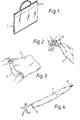
- Fig.1 is a perspective view illustrating a compact packaged plastic balloon in accordance with the present invention;
- Fig. 2 is a partial, diagrammatic view illustrating one technique of operatively sealing an end of the balloon;
- Fig. 3 is a partial, diagrammatic view which illustrates one technique of manually maintaining an end of the plastictube of the balloon open to the ambient atmosphere to facilitate the flow of air into the tube;
- Fig. 4 is a reduced-size diagrammatic view which illustrates a technique of running with the tube to facilitate the flow of air into the tube;
- Fig. 5 is a reduced-size diagrammatic view which illustrates a technique of moving the open end of the tube up and down to facilitate the flow of air into the tube;
- Fig. 6 is a cross-sectional view of the plastic tube taken along the lines 6-6 of Fig. 5 and looking in the direction of the arrows;
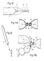
- Fig. 7 is a partial diagrammatic view which illustrates a pair of partially inflated plastic tubes operatively tied to one another;
- Fig. 8 is a reduced-size diagrammatic illustration of a plurality of the partially inflated plastic tubes twisted together and tied into knot-type forms to provide a water flotation device;
- Fig. 9 is a reduced-size diagrammatic view which illustrates the use of a plurality of inflated tubes as a sculpture or art medium;
- Fig. 10 is a partial diagrammatic view illustrating a technique for further facilitating the inflation of the plastic tube by air already trapped therein;
- Figs. 11A and 11B are partial cross-sectional views illustrating the technique of interconnecting two or more plastic tubes by means of cylindrical conduits; and
- Fig. 12 is a reduced-size diagrammatic view of an inflated tube used as a lighter than air, buoyant body.
- With general reference to the Figures, industrially available thin, flexible, gas-impermeable and substantially non-elastic plastic material is used to provide a
balloon 2 in the form of a long tube. According to the present invention, such material may be formed of any plastic having such properties including polyethylene, polyvinyl chloride or polypropylene. Typical uses of such plastic material include use in agricultural hot- houses, packing and plastic bags. However, upon the inflation thereof and the closing of the ends, a large balloon-type structure is produced which readily lends itself to use in children's games, as an art or advertising medium, decoration, or a flotation device upon which people can rest and float in shallow water. - With specific reference to Figure 1, the thin
plastic material 2 is very lightweight and flexible such that when deflated, the material may be folded into a very compact form and placed in a small plastic carrying case 4 or any other convenient carrying means. - Two methods of inflating the
plastic tube 2 in accordance with the present invention will be described with reference to Figures 2 through 5 and 10. As shown in Figure 2, one of the ends of theplastic tube 2 is operatively sealed by means of aknot 8 or by any other convenient means such as by twisting a paper-covered wire over the end of the tube in a well known manner, or by any other suitable means. As shown in Figure 3, the user manually maintains the other end of thetube 6 open to the ambient atmosphere to thereby facilitate the flow of air into the tube. While Figure 3 illustrates the use of both hands to maintainend 6 of the tube open to the ambient atmosphere, only a single hand may be required under many circumstances, especially when larger-diameter tubes are being used, as illustrated in Figure 4, for example. While maintainingend 6 of the tube open to the ambient atmosphere, the user, if outdoors, may simply run with the tube while holding open theunsealed end 6 so that the movement through the atmosphere is used to force air to enter thetube 2. Since the plastic material is very lightweight, the entire tube will thus be easily inflated, and theunsealed end 6 is then sealed in a manner similar to that employed for the other end, thereby preventing escape of air from the gas-impermeable tube. - The second method of inflating the tube is illustrated in Figure 5. Again maintaining
end 6 of the tube open to the ambient atmosphere, the user, if indoors or confined within a small area, rapidly moves the open end of the tube up and down, the opening of the tube facing the direction of upward or downward travel. Air will thus be forced into the tube, allowing the tube to be inflated without running. - Figure 10 illustrates a technique for further facilitating the flow of air into a plastic tube, especially for relatively long tubes. Upon the initial flow of air into the open end of the tube, the air inside the tube may be forced toward the tied end of the tube in the following manner. First, the user grasps the open end of the tube to prevent the escape of air from the tube, the user's hands being in positions "A" and "B" as shown. The air at the open end of the tube may be forced toward the sealed end of the tube by the user sliding his hand toward the sealed end of the tube while constricting the tube to keep as little air as possible from escaping at the open end. As the user moves his hand to position "C" to force the air toward the sealed end, the user's other hand is kept at the open end in position "A". Thus, by repeatedly scooping air into the open end of the tube as shown in Figs. 4 or 5, and by repeatedly forcing the air toward the sealed end of the tube, extremely long tubes may be tightly inflated. A knot is then formed at position "C" to thereby seal the end of the tube.
- Fig. 6 illustrates a cross-section view of the plastic tube taken along line 6-6 of Fig. 5. The plastic material is typically very thin such as polyethylene or polyvinyl chloride or polypropylene. The material is typically translucent and available in a wide range of pastel colours. Additionally, such plastic material is usually very durable and can be twisted and flexed over long periods of time without tearing. The material is also very lightweight, tubes of up to 20 m. weighing only a few grams.
- While the inflated tubes may be used by children simply as a balloon-type amusement device, Figures 7-9, 11A, 11B and 12 illustrate further uses of the inflated tube. Figure 7 illustrates a pair of
tubes 2 and 2' being tied to one another at their ends by a common knot 8'. Additional inflated tubes may further be tied to the common knot 8' or may be tied to other parts of thetubes 2 or 2' or to the other end oftubes 2 or 2' to form large structures of arbitrary shapes and configurations. - Figure 8 illustrates a plurality of inflated tubes twisted together and tied in knot-type forms which may be used as a flotation device in a shallow body of
water 10. In accordance with this specific embodiment of the invention, a plurality of tubes may be used as a "free-form" water raft. It should be noted, however, that the tubes should not be used as a safety device or flotation device in deep water, since the thin plastic material is subject to punctures. The tubes are thus rendered safe as flotation devices only in shallow water where the user can otherwise comfortably stand with his upper body well above the water level. - Figure 9 illustrates the use of a plurality of inflated tubes as an art medium, specifically a sculpture medium.
Tube 14 is shown as being partially inflated and disposed in an arc or "rainbow" configuration, whiletube 16 is vertically oriented, a knot being formed at the top 18 thereof. By painting or printing messages or slogans on the surface of the tubes, the tubes may be used as an advertising medium as well as an art or sculpture medium. - If it is desired to bend and shape the tube at a plurality of locations, the tube should not be fully inflated since the plastic material is non-elastic.
- Figures 11A and 11 B illustrate a technique of interconnecting two or more plastic tube sections using cylindrical conduits as an alternative to the technique described by reference to Figure 7. Specifically, Figure 11A illustrates the technique of providing a straight
cylindrical conduit 20 disposed within one end oftube section 2a and within one end oftube section 2b. The end oftube section 2a is sealed aroundconduit 20 by means of a string orwire 22a, while the end oftube section 2b is similarly sealed aboutconduit 20 by means of a string orwire 22b. In Figure 11 B, thecylindrical conduit 24 is "Y" shaped, thus interconnecting threetube sections tube sections conduit 24 by means of strings orwires -
Conduits - Still another use of the tubes is as a lighter than-air body which will naturally rise in the ambient atmosphere, yet which requires no special gas such as helium or the like. Specifically, by inflating a large tube which is colored black or another dark color, the air within the tube, when expected to direct sunlight over a given period of time, will rise significantly in temperature since the black or dark material of the tube will react to the sunlight and produce heat thereby heating the air within the tube. As the air within the tube increases in temperature it expands, and the tube will eventually become buoyant in the atmosphere and will naturally rise, as illustrated in Figure 12.
- Unlike other balloon-type amusement devices, the present invention is readily available in almost unlimited lengths. The balloon-type structures may be as large as 20 m. in length or more, yet fold up to a very compact size when not inflated. The plastic material is tough and durable and is fully reusable. However, should small holes or rips in the material occur, such can easily be repaired by simply using an adhesive, cellulose or plastic tape to cover any holes or rips. Finally, while the plastic tube may be inflated using conventional means such as an air compressor, the tube in accordance with the present invention readily lends itself to inflation by the above described methods which require no mechanical equipment and which may easily be accomplished by children.
- While the preferred embodiments have been described in the specification, the scope of the invention shall be defined with reference to the following claims.
Claims (5)
Priority Applications (1)
| Application Number | Priority Date | Filing Date | Title |
|---|---|---|---|
| AT82305503T ATE25589T1 (en) | 1981-10-16 | 1982-10-15 | BALLOON. |
Applications Claiming Priority (2)
| Application Number | Priority Date | Filing Date | Title |
|---|---|---|---|
| US31208481A | 1981-10-16 | 1981-10-16 | |
| US312084 | 1981-10-16 |
Publications (2)
| Publication Number | Publication Date |
|---|---|
| EP0081899A1 EP0081899A1 (en) | 1983-06-22 |
| EP0081899B1 true EP0081899B1 (en) | 1987-03-04 |
Family
ID=23209805
Family Applications (1)
| Application Number | Title | Priority Date | Filing Date |
|---|---|---|---|
| EP82305503A Expired EP0081899B1 (en) | 1981-10-16 | 1982-10-15 | Recreational balloon |
Country Status (8)
| Country | Link |
|---|---|
| EP (1) | EP0081899B1 (en) |
| JP (1) | JPS5899979A (en) |
| AT (1) | ATE25589T1 (en) |
| AU (1) | AU557904B2 (en) |
| CA (1) | CA1192048A (en) |
| DE (1) | DE3275502D1 (en) |
| DK (1) | DK452582A (en) |
| ZA (1) | ZA827475B (en) |
Families Citing this family (5)
| Publication number | Priority date | Publication date | Assignee | Title |
|---|---|---|---|---|
| US4693695A (en) * | 1986-03-31 | 1987-09-15 | Cheng Peter S C | Ascending and descending balloon action toy |
| US5186675A (en) * | 1991-11-19 | 1993-02-16 | Stoddard Robert D D | Air vent toy |
| EP0784310A3 (en) * | 1996-01-11 | 1999-07-14 | Guy Laufer | Amusement device |
| WO2002066132A1 (en) * | 2001-02-23 | 2002-08-29 | Marin Hernandez Flavio V | Inflatable toy |
| US20080045117A1 (en) * | 2002-03-13 | 2008-02-21 | Flavio Valerio Marin Hernandez | Inflatable Toy And Its Manufacturing Process |
Family Cites Families (11)
| Publication number | Priority date | Publication date | Assignee | Title |
|---|---|---|---|---|
| FR1317787A (en) * | 1963-05-08 | |||
| US2688207A (en) * | 1950-12-12 | 1954-09-07 | Us Rubber Co | Ridable water toy |
| US2731768A (en) * | 1952-09-11 | 1956-01-24 | Ideal Toy Corp | Inflatable toy device |
| US3071892A (en) * | 1960-04-07 | 1963-01-08 | Gadget Of The Month Club Inc | Inflatable travel toy |
| US3153878A (en) * | 1960-04-11 | 1964-10-27 | Jr Bonne Smith | Flying solarthermic toy airship |
| DE1495730B2 (en) * | 1963-07-24 | 1971-03-18 | Farbenfabriken Bayer AG, 5090 Le verkusen | PROCESS FOR MANUFACTURING THERMOPLASTIC POLYCONDENSATION PRODUCTS |
| US3671350A (en) * | 1969-12-24 | 1972-06-20 | Edward B Westlake Jr | Method of producing a plastic shopping bag |
| JPS4820598B1 (en) * | 1970-02-16 | 1973-06-22 | ||
| US4053376A (en) * | 1976-10-27 | 1977-10-11 | Ppg Industries, Inc. | Electrolytic production of hydrogen iodide |
| DE7734838U1 (en) * | 1977-11-14 | 1978-04-20 | Heimann, Alexander, 3000 Hannover | DRAGONS |
| US4213267A (en) * | 1979-01-02 | 1980-07-22 | Curtis Eugene E | Composite balloon figure and method of making the same |
-
1982
- 1982-10-07 AU AU89186/82A patent/AU557904B2/en not_active Expired
- 1982-10-13 DK DK452582A patent/DK452582A/en not_active Application Discontinuation
- 1982-10-13 ZA ZA827475A patent/ZA827475B/en unknown
- 1982-10-13 CA CA000413342A patent/CA1192048A/en not_active Expired
- 1982-10-15 DE DE8282305503T patent/DE3275502D1/en not_active Expired
- 1982-10-15 AT AT82305503T patent/ATE25589T1/en active
- 1982-10-15 EP EP82305503A patent/EP0081899B1/en not_active Expired
- 1982-10-16 JP JP57182028A patent/JPS5899979A/en active Pending
Also Published As
| Publication number | Publication date |
|---|---|
| CA1192048A (en) | 1985-08-20 |
| DK452582A (en) | 1983-04-17 |
| JPS5899979A (en) | 1983-06-14 |
| DE3275502D1 (en) | 1987-04-09 |
| EP0081899A1 (en) | 1983-06-22 |
| AU557904B2 (en) | 1987-01-15 |
| ZA827475B (en) | 1983-09-28 |
| ATE25589T1 (en) | 1987-03-15 |
| AU8918682A (en) | 1983-04-21 |
Similar Documents
| Publication | Publication Date | Title |
|---|---|---|
| US5215492A (en) | Toy balloon with cool illumination | |
| US4034501A (en) | Unitary inflation devices for helium balloons and their like | |
| US4778431A (en) | Animated balloons | |
| US5243707A (en) | Novelty inflatable hats | |
| US3523563A (en) | Integrally formed self-sealing valve having additionally integral means to render valve airtight | |
| US4986540A (en) | Erratically movable inflated game ball | |
| US4758199A (en) | Toy balloon | |
| US20060223411A1 (en) | Lighter than air novelty figure | |
| US9415321B2 (en) | Self-sealing balloon or bladder | |
| US20070161322A1 (en) | Multi-segment animation balloon | |
| US6048591A (en) | Christmas tree ornament | |
| EP0081899B1 (en) | Recreational balloon | |
| US3180639A (en) | Inflatable toy and display device | |
| US5613892A (en) | Inflatable plush toy | |
| US6659838B1 (en) | Rigid helium balloons | |
| US7223151B2 (en) | Rigid ballon | |
| US20120184176A1 (en) | Aerostats with linear/non-linear gas filled connecting ladder structures | |
| GB2200299A (en) | Sealing inflation necks of inflatable items | |
| US6019660A (en) | Balloon for interlocking with another balloon | |
| US10843098B1 (en) | Dynamic balloon apparatus | |
| US2920419A (en) | Toy whale | |
| US3025635A (en) | Rocket toy balloon | |
| US4356661A (en) | Aerostat and method of operation | |
| JP2004520136A (en) | Inflatable toys | |
| CN206103344U (en) | Inflation model freely movable joint device |
Legal Events
| Date | Code | Title | Description |
|---|---|---|---|
| PUAI | Public reference made under article 153(3) epc to a published international application that has entered the european phase |
Free format text: ORIGINAL CODE: 0009012 |
|
| AK | Designated contracting states |
Designated state(s): AT BE CH DE FR GB IT LI NL SE |
|
| 17P | Request for examination filed |
Effective date: 19831217 |
|
| ITF | It: translation for a ep patent filed |
Owner name: DR. ING. A. RACHELI & C. |
|
| GRAA | (expected) grant |
Free format text: ORIGINAL CODE: 0009210 |
|
| AK | Designated contracting states |
Kind code of ref document: B1 Designated state(s): AT BE CH DE FR GB IT LI NL SE |
|
| PG25 | Lapsed in a contracting state [announced via postgrant information from national office to epo] |
Ref country code: SE Effective date: 19870304 Ref country code: NL Effective date: 19870304 Ref country code: LI Effective date: 19870304 Ref country code: CH Effective date: 19870304 Ref country code: BE Effective date: 19870304 Ref country code: AT Effective date: 19870304 |
|
| REF | Corresponds to: |
Ref document number: 25589 Country of ref document: AT Date of ref document: 19870315 Kind code of ref document: T |
|
| REF | Corresponds to: |
Ref document number: 3275502 Country of ref document: DE Date of ref document: 19870409 |
|
| ET | Fr: translation filed | ||
| REG | Reference to a national code |
Ref country code: CH Ref legal event code: PL |
|
| NLV1 | Nl: lapsed or annulled due to failure to fulfill the requirements of art. 29p and 29m of the patents act | ||
| PLBE | No opposition filed within time limit |
Free format text: ORIGINAL CODE: 0009261 |
|
| STAA | Information on the status of an ep patent application or granted ep patent |
Free format text: STATUS: NO OPPOSITION FILED WITHIN TIME LIMIT |
|
| 26N | No opposition filed | ||
| ITTA | It: last paid annual fee | ||
| PGFP | Annual fee paid to national office [announced via postgrant information from national office to epo] |
Ref country code: DE Payment date: 19941010 Year of fee payment: 13 |
|
| PGFP | Annual fee paid to national office [announced via postgrant information from national office to epo] |
Ref country code: GB Payment date: 19951011 Year of fee payment: 14 |
|
| PGFP | Annual fee paid to national office [announced via postgrant information from national office to epo] |
Ref country code: FR Payment date: 19951024 Year of fee payment: 14 |
|
| PG25 | Lapsed in a contracting state [announced via postgrant information from national office to epo] |
Ref country code: DE Effective date: 19960801 |
|
| PG25 | Lapsed in a contracting state [announced via postgrant information from national office to epo] |
Ref country code: GB Effective date: 19961015 |
|
| GBPC | Gb: european patent ceased through non-payment of renewal fee |
Effective date: 19961015 |
|
| PG25 | Lapsed in a contracting state [announced via postgrant information from national office to epo] |
Ref country code: FR Effective date: 19970630 |
|
| REG | Reference to a national code |
Ref country code: FR Ref legal event code: ST |