EP0081839B1 - Electron beam focusing lens - Google Patents
Electron beam focusing lens Download PDFInfo
- Publication number
- EP0081839B1 EP0081839B1 EP82111575A EP82111575A EP0081839B1 EP 0081839 B1 EP0081839 B1 EP 0081839B1 EP 82111575 A EP82111575 A EP 82111575A EP 82111575 A EP82111575 A EP 82111575A EP 0081839 B1 EP0081839 B1 EP 0081839B1
- Authority
- EP
- European Patent Office
- Prior art keywords
- electrode
- annular ring
- focusing lens
- electron beam
- potential
- Prior art date
- Legal status (The legal status is an assumption and is not a legal conclusion. Google has not performed a legal analysis and makes no representation as to the accuracy of the status listed.)
- Expired
Links
Images


Classifications
-
- H—ELECTRICITY
- H01—ELECTRIC ELEMENTS
- H01J—ELECTRIC DISCHARGE TUBES OR DISCHARGE LAMPS
- H01J29/00—Details of cathode-ray tubes or of electron-beam tubes of the types covered by group H01J31/00
- H01J29/46—Arrangements of electrodes and associated parts for generating or controlling the ray or beam, e.g. electron-optical arrangement
- H01J29/58—Arrangements for focusing or reflecting ray or beam
- H01J29/62—Electrostatic lenses
-
- H—ELECTRICITY
- H01—ELECTRIC ELEMENTS
- H01J—ELECTRIC DISCHARGE TUBES OR DISCHARGE LAMPS
- H01J29/00—Details of cathode-ray tubes or of electron-beam tubes of the types covered by group H01J31/00
- H01J29/46—Arrangements of electrodes and associated parts for generating or controlling the ray or beam, e.g. electron-optical arrangement
- H01J29/48—Electron guns
- H01J29/488—Schematic arrangements of the electrodes for beam forming; Place and form of the elecrodes
-
- H—ELECTRICITY
- H01—ELECTRIC ELEMENTS
- H01J—ELECTRIC DISCHARGE TUBES OR DISCHARGE LAMPS
- H01J29/00—Details of cathode-ray tubes or of electron-beam tubes of the types covered by group H01J31/00
- H01J29/46—Arrangements of electrodes and associated parts for generating or controlling the ray or beam, e.g. electron-optical arrangement
- H01J29/58—Arrangements for focusing or reflecting ray or beam
- H01J29/62—Electrostatic lenses
- H01J29/622—Electrostatic lenses producing fields exhibiting symmetry of revolution
Definitions
- the present invention relates to an electron beam focusing lens for forming an electrostatic focusing field to focus an electron beam, and more particularly to an electrostatic focusing lens suitable for use in an image pickup tube, a cathode-ray tube or the like.
- an image pickup tube of electrostatic focusing type a photoconductive film is scanned, by an electron beam which is focused by a focusing lens, to convert an optical signal into an electrical signal. Accordingly, the resolution of the image pickup tube is mainly determined by the spot diameter of the focused electron beam.
- An electron gun in the image pickup tube of electrostatic focusing type generally includes two fundamental parts, that is, an electron beam generating portion and an electron beam focusing lens (namely, a main lens).
- Fig. 1 shows in cross section an image pickup tube of electrostatic focusing type.
- reference numeral 1 designates an evacuated envelope, 2 a cathode, 3 a grid and 4 an anode.
- the cathode 2, grid 3 and anode 4 make up triode section 14 which is the electron beam generating portion.
- Reference numerals 5, 6 and 7 designate cylindrical electrodes which form the electron focusing lens (namely, main lens), 9 a mesh electrode for forming a main lens portion 15 together with the electrodes 5, 6 and 7, 10 a photoconductive film, and 13 a deflection coil disposed outside the image pickup tube.
- An electron beam emitted from the cathode 2 is focused by a lens formed at the triode section 14 to form a crossover point, and then passes through a beam-limiting aperture 8 provided in the anode 4.
- the electron beam having passed through the aperture 8 is focused by the focusing lens or main lens made up of the electrodes 5, 6 and 7, as indicated by an electron trajectory 11.
- the electron beam is deflected, as indicated by a trajectory 12, due to a magnetic field generated by the deflection coil 13 to scan the photoconductive film 10. Further, the deflected electron beam impinges vertically upon the photoconductive film 10 by the action of a collimation lens formed by the electrode 7 and the mesh electrode 9.
- the electrode 5 and the mesh electrode 9 are electrically connected to each other and are applied with a high potential, for example, about 1400 V.
- the electrode 6 is applied with a low potential, for example, about 250 V
- the electrode 7 is applied with a potential (for example, about 770 V) which is intermediate between the potentials of the electrodes 6 and 9.
- the electrodes 5, 6, and 9 form a unipotential focusing lens, and the electron beam having passed through the beam-limiting aperture 8 is focused mainly by the main lens formed by the electrodes 5, 6 and 7, to form a substantially minimum spot on the photoconductive film 10.
- FIG. 2a shows the cross section of a typical uni-potential focusing lens while illustrating an axial potential distribution 0 in the axial direction and the distribution of the second derivative ⁇ " of the axial potential with respect to the position in the axial direction.
- Fig. 2b shows the cross section of a typical bi-potential focusing lens while illustrating an axial potential distribution 0 in the axial direction and the distribution of the second derivative ⁇ " of the axial potential with respect to the position in the axial direction.
- the second derivative distribution ⁇ 1>" has a close relationship with the focusing action of the lens.
- the resolution of an image pickup tube, a cathode-ray tube or the like is mainly determined by the spot diameter of the focused electron beam.
- it is required to make the spherical aberration of the focusing lens or main lens as small as possible.
- Fig. 3 shows the cross section of an EFL while illustrating an axial potential distribution 0 and the distribution of the second derivative ⁇ " of the axial potential.
- the EFL has a structure that at least three cylindrical electrodes (four cylindrical electrodes in Fig. 3) are arranged face to face with each other.
- US-A-3 090 882 relates to an electron gun for cathode ray tubes comprising an electron beam focusing lens for forming an electrostatic focusing field.
- the lens comprises a first substantially cylindrical electrode as well as a second substantially cylindrical electrode. Said two electrodes are coaxially aligned along the axis of the lens. The ends of said two cylindrical electrodes are facing each other whereby one of the electrodes is applied with an electric potential which is lower than the electric potential applied to the other electrode.
- the high potential electrode of that 2-electrode focusing system includes a transverse end portion which is adjacent to the low-potential electrode and has a central aperture.
- Such electrode construction results in the creation of a high voltage focusing field extending into the cross-over region of the beam, thereby providing a decrease of blooming. Moreover, since the shape of the focusing field created is not severely altered in response to a substantial adjustment change of the voltage in the low potential electrode, depth of focus is substantially increased.
- FR-A-1 309 662 there is known another electron beam focusing lens comprising two electrodes, one being applied with a lower and one being supplied with a higher electric potential.
- the end portion of the high potential electrode facing the low potential electrode is in the form of a hemisphere which is provided in its central axis portion with an aperture.
- the maximum diameter of that hemisphere portion is smaller than the diameter of the remained portion of that electrode, which is in the form of a cylinder.
- Another electron beam focusing lens is known from FR-A-2 436 493, in which the temperature end portion of the high potential electrode has an inwardly directed frusto-conical shape. This electrode construction limits the spherical observation.
- An object of the present invention is to provide an electron beam focusing lens in which the spherical aberration is reduced, thereby improving the characteristics of beam spot.
- the minimum spot of a focused electron beam has a definite diameter which is dependent on the spherical aberration of a focusing lens used (hereinafter referred to as "the diameter of circle of least confusion").
- the radius of the minimum beam spot is given by 1/4MC S a 3 , where M indicates a lateral magnification, C s a sphercial aberration coefficient, and a an incident angle electron beam. Accordingly, the diameter Do of circle of least confusion is given by the following equation:
- the beam spot diameter decreases as the spherical aberration coefficient C s is smaller.
- the spherical aberration coefficient C s is given by the following equation: where S indicates a ratio ⁇ '(Z)/ ⁇ (Z), 0(Z) an axial potential (namely, an electric potential on the lens axis), Z a coordinate in the axial direction, Z o the position of an entrance of the lens, Z 1 the position of an exit of the lens, ['] the differentiation with respect to Z, and H(Z) the distance of an electron trajectory from the lens axis in each coordinate Z.
- the present invention is based upon the fact that the spherical aberration of an electrostatic focusing lens can be reduced by causing an axial potential distribution to have a gentle slope on the low potential side and a steep slope on the high potential side.
- an emulsion ring electrode having an aperture is provided at an end face of a high-potential electrode opposite to a low-potential electrode, thereby suppressing the penetration of an electric potential from the low-potential electrode into the high-potential electrode to make the slope of the axial potential distribution on the high potential side steeper than that on the low potential side.
- the annular ring electrode 19 has the aperture 19a at its central portion.
- the height or projection length of the circularly curved portion in a direction of the lens axis increases with an increased distance from the outer circumference of the annular ring electrode 19 toward the center axis of the aperture or the lens axis until it reaches the maximum value at 19c, and then decreases with a further increased distance from the outer circumference of the annular ring electrode 19 until it takes the minimum value at the edge of the aperture 19a or the inner circumference of the annular ring electrode 19 which is in the same level as the outer circumference of the annular ring electrode 19.
- the annular ring electrode 19 has the form of an annular ring formed in such a manner that a circular arc which is convex toward the low-potential electrode 16 between the outer and inner circumferences of the electrode 19 is rotated about the center axis of the aperture 19a.
- reference character / designates the maximum height at the peak position 19c, and d a distance in a radial direction between the outer circumference of the annular ring electrode 19 and the inner circumference thereof or the edge of the aperture 19a. It is preferable to make the diameter b of the aperture 19a equal to or smaller than eight-tenths of the inner diameter a of the high-potential cylindrical electrode 17 but larger than a certain value so that an electron beam is not interrupted by the plate electrode 19. This holds for the following embodiments.
- the spherical aberration coefficient C s of the focusing lens having the structure shown in Fig. 4 has been calculated from the equation (2), for various values of the maximum height / of the circular curved portion of the annular ring electrode 19.
- the ratio I/d is selected to be less than 0.5, can be made smaller than that of a flat focusing lens. In the figure 4 embodiment, it is best that the ratio I/d is made 0.2 to 0.3.
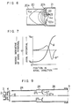
- Fig. 6 shows, in section, a main part of an electron beam focusing lens according to a further embodiment of the present invention which is widely applicable to an electron gun.
- the focusing lens shown in Fig. 6 is made up of at least two cylindrical electrodes having a common axis, that is, an electrode 20 to be applied with a low-potential V LO and an electrode 21 to be applied with a high potential V HI .
- the low-potential electrode 20 has a cylinder portion 20a and a truncated cone portion 20b whose inner diameter is maximum at an end opposite to the high-potential electrode 21.
- the high-potential electrode 21 is a cylinder having an inner diameter approximately equal to the maximum inner diameter of the truncated cone portion 20b, and an annular ring electrode 22 having a circularly curved portion convex toward the low-potential electrode 20 is provided at an end face of the high-potential electrode 21 opposite to the low-potential electrode 20.
- the annular ring electrode 22 is provided with an electron beam permeable aperture 22a at a central portion thereof.
- the shape of the annular ring electrode 22 is similar to that of the annular ring electrode 19 in Fig. 4.
- Fig. 6 also shows equipotential lines 23.
- Fig. 7 shows an axial potential distribution ⁇ and the distribution of the second derivative ⁇ " of the axial potential in the Figure 6 embodiment. As is apparent from Fig.
- the axial potential distribution ⁇ monotonically increasing from the low potential V LO to the high potential V HI varies gently in a range where the second derivative distribution ⁇ " has a positive gradient, but varies steeply in a range where q)" has a negative gradient.
- the cylinder portion 20a of the electrode 20 has an inner diameter of about 11 mm, and the truncated cone portion 20b thereof has an axial length of about 2 mm and the maximum inner diameter of about 12 mm.
- the cylinder electrode 21 has an inner diameter of about 12 mm.
- the aperture 22a of the annular ring electrode 22 has a diameter of about 4mm, and the distance in a radial direction between the outer and inner circumferences of the annular ring electrode 22 is about 4 mm.
- a peak of the projection of the circular curved portion of the annular ring electrode 22 is positioned at the middle between the outer and inner circumferences of the annular ring electrode and distanced from the center axis of the aperture 22a by about 4 mm the height of the peak is about 1 mm. Accordingly, the peak of the circularly curved portion is in a position distanced from the center axis of the aperture 22a by about 66% of the inner diameter of the high-potential electrode 21, the maximum height of the circularly curved portion at the peak position is about 25% of the distance in a radial direction between the outer and inner circumferences of the plate annular ring electrode 22, and the diameter of the aperture 22a is about 33% of the inner diameter of the high-potential electrode 21.
- the electron beam trajectory in the focusing lens shown in Fig. 6 has been calculated for various values of the lateral magnification M which are obtained by varying the position of an object point (namely, the starting point of electron beam) on the lens axis.
- the spherical aberration coefficient C s has been calculated from the equation (1).
- Fig. 8 shows the resulting relation 91 between the lateral magnification M and the spherical aberration coefficient C s .
- Fig. 8 also shows a similar relation 92 obtained when the same operating condition as the focusing lens of Fig.
- the bi-potential lens of Fig. 2b is applied to the bi-potential lens of Fig. 2b as a typical one of conventional focusing lenses in which two cylindrical electrodes with the same inner diameter are arranged face to face with each other.
- the focusing lens according to the present invention is far smaller in spherical aberration than the conventional bi-potential focusing lens.
- Fig. 9 shows a still further embodiment of an electron beam focusing lens according to the present invention which forms the main lens portion of an image pickup tube.
- Fig. 9 is a sectional view showing the electrode structure to the image pickup tube.
- the focusing lens according to the present embodiments includes three cylindrical electrodes 24, 25 and 26 arranged coaxially.
- the inner diameters of the electrodes 25 and 26 are substantially equal to each other and the inner diameter of the electrode 24 is slightly smaller than those of the electrodes 25 and 26.
- An annular ring electrode 27 is provided at an end face of the electrode 26 opposite to the electrode 25.
- the annular ring electrode 27 has an aperture 27a at its central portion and has a circularly curved portion which is convex toward the electrode 25.
- the electrodes 24,25 and 26 form the main lens while the electrode 26 and a mesh electrode 9 form a collimation lens.
- the operation of an image pickup tube has been explained with reference to Fig. 1, and therefore such explanation will be omitted here.
- an electric potential applied to the electrode 24 is made nearly equal to 10% of that applied to the electrode 26 while the electrode 25 is applied with a potential which is intermediate between the potentials applied to the electrodes 24 and 26.
- the electrodes 24, 25 and 26 are applied with about 90, 300 and 770 V, respectively, and the mesh electrode 9 is applied with 1400 V.
- the electrode 24 has an inner diameter of about 10 mm and an axial length of about 27 mm
- the electrode 25 has an inner diameter of about 12 mm and an axial length of about 5 mm
- the electrode 26 has an inner diameter of about 12 mm and an axial length of about 26 mm.
- the height of the curved portion of the plate electrode 27 in a direction of the lens axis from the end face of the electrode 26 is about 0.5 mm, and a peak of the projection of the curved portion is positioned outside the middle between the outer and inner circumferences of the annular ring electrode.
- the annular ring electrode 27 is curved so that the inner circumference thereof or the edge of the aperture 27a extends into the inside of the electrode 26.
- the annular ring electrode 27 provided with the aperture 27a at its central portion has the form of a curved annular ring in which the height in a direction of the lens axis increases with an increased distance from the outer circumference of the annular ring electrode 27 toward the center axis of the aperture 27a until it reaches the maximum value at 27c, and then decreases with a further increased distance from the outer circumference of the annular ring electrode 27 until it takes the minimum value at the edge of the aperture 27a or the inner circumference of the annular ring electrode 27 which is in a level lower than the outer circumference of the annular ring electrode 27.
- a distance in a radial direction between the outer circumference of the annular ring electrode 27 and the inner circumference thereof or the edge of the aperture 27a is about 4 mm, and the diameter of the aperture 27a is nearly equal to 4 mm in order not to interrupt the deflected electron trajectory. That is, the diameter of the aperture 27a is about 33% of the inner diameter of the electrode 2b, and the maximum height of the circularly curved portion is about 13% of the distance in a radial direction between the outer and inner circumferences of the annular ring electrode 27.
- the total length of the main lens portion is about 63 mm which is about 17% shorter than a typical total length (about 76 mm) of the main lens portion of the conventional image pickup tube. This provides an additional advantage in that the tube length can be shortened.
- an image pickup tube provided with the present embodiment has been made identical in lateral magnification of image and angular magnification of electron beam to a conventional image pickup tube so that these image pickup tubes are equal in the spread of beam spot due to thermal energy of electrons emitted from a hot cathode.
- the position of a deflection coil mounted around the tube having the present embodiment has been adjusted to make the spot diameter of the deflected electron beam equal to that in the conventional tube.
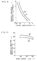
- the electron trajectory in each of these image pickup tubes has been calculated to obtain the diameter D c of a circle of least confusion.
- Fig. 10 shows a relation between the incident angle a of electron beam and the diameter D c of circle of least confusion for each of these tubes.
- a line 93 corresponds to the inventive tube and a line 94 corresponds to the conventional tube.
- a line 94 corresponds to the conventional tube.
- Fig. 10 shows a relation between a beam current and the resolution measured at the center of picture surface (the degree of amplitude modulation for a vertical stripe pattern of 400 TV lines) for the inventive tube and the conventional tube.
- a curve 95 corresponds to the inventive tube while a curve 96 corresponds to the conventional tube.
- a focusing lens according to the present invention can be used as a low spherical aberration lens in an electron gun of an image pickup tube, a cathode-ray tube or the like.
Description
- The present invention relates to an electron beam focusing lens for forming an electrostatic focusing field to focus an electron beam, and more particularly to an electrostatic focusing lens suitable for use in an image pickup tube, a cathode-ray tube or the like.
- For easy understanding of an electron beam focusing lens, an image pickup tube provided with a conventional focusing lens of this kind will be explained with reference to Fig. 1, by way of example.
- In an image pickup tube of electrostatic focusing type, a photoconductive film is scanned, by an electron beam which is focused by a focusing lens, to convert an optical signal into an electrical signal. Accordingly, the resolution of the image pickup tube is mainly determined by the spot diameter of the focused electron beam.
- An electron gun in the image pickup tube of electrostatic focusing type generally includes two fundamental parts, that is, an electron beam generating portion and an electron beam focusing lens (namely, a main lens). Fig. 1 shows in cross section an image pickup tube of electrostatic focusing type. In Fig. 1,
reference numeral 1 designates an evacuated envelope, 2 a cathode, 3 a grid and 4 an anode. Thecathode 2,grid 3 andanode 4 make uptriode section 14 which is the electron beam generating portion.Reference numerals main lens portion 15 together with theelectrodes cathode 2 is focused by a lens formed at thetriode section 14 to form a crossover point, and then passes through a beam-limitingaperture 8 provided in theanode 4. The electron beam having passed through theaperture 8 is focused by the focusing lens or main lens made up of theelectrodes trajectory 12, due to a magnetic field generated by thedeflection coil 13 to scan thephotoconductive film 10. Further, the deflected electron beam impinges vertically upon thephotoconductive film 10 by the action of a collimation lens formed by the electrode 7 and themesh electrode 9. Usually, theelectrode 5 and themesh electrode 9 are electrically connected to each other and are applied with a high potential, for example, about 1400 V. Theelectrode 6 is applied with a low potential, for example, about 250 V, and the electrode 7 is applied with a potential (for example, about 770 V) which is intermediate between the potentials of theelectrodes electrodes aperture 8 is focused mainly by the main lens formed by theelectrodes photoconductive film 10. - A uni-potential focusing type and a bi-potential focusing type have been widely used as the electron beam focusing lens in an image pickup tube. Fig. 2a shows the cross section of a typical uni-potential focusing lens while illustrating an axial potential distribution 0 in the axial direction and the distribution of the second derivative φ" of the axial potential with respect to the position in the axial direction. Fig. 2b shows the cross section of a typical bi-potential focusing lens while illustrating an axial potential distribution 0 in the axial direction and the distribution of the second derivative φ" of the axial potential with respect to the position in the axial direction. The second derivative distribution <1>" has a close relationship with the focusing action of the lens. The resolution of an image pickup tube, a cathode-ray tube or the like is mainly determined by the spot diameter of the focused electron beam. In order to make small the beam spot diameter, it is required to make the spherical aberration of the focusing lens or main lens as small as possible.
- However, conventional electrostatic lenses used as the focusing lens in an electron gun involve large spherical aberration. In order to reduce the spherical aberration, an EFL (extended field lens) has been proposed which is based upon the concept that the spherical aberration can be reduced by causing an axial potential distribution to have a gentle slope while making the second derivative of axial potential as small as possible in a region where the axial potential has small values. See JP-A-76072n6. Fig. 3 shows the cross section of an EFL while illustrating an axial potential distribution 0 and the distribution of the second derivative φ" of the axial potential. As shown in Fig. 3, the EFL has a structure that at least three cylindrical electrodes (four cylindrical electrodes in Fig. 3) are arranged face to face with each other.
- US-A-3 090 882 relates to an electron gun for cathode ray tubes comprising an electron beam focusing lens for forming an electrostatic focusing field. The lens comprises a first substantially cylindrical electrode as well as a second substantially cylindrical electrode. Said two electrodes are coaxially aligned along the axis of the lens. The ends of said two cylindrical electrodes are facing each other whereby one of the electrodes is applied with an electric potential which is lower than the electric potential applied to the other electrode. The high potential electrode of that 2-electrode focusing system includes a transverse end portion which is adjacent to the low-potential electrode and has a central aperture. Such electrode construction results in the creation of a high voltage focusing field extending into the cross-over region of the beam, thereby providing a decrease of blooming. Moreover, since the shape of the focusing field created is not severely altered in response to a substantial adjustment change of the voltage in the low potential electrode, depth of focus is substantially increased.
- From FR-A-1 309 662 there is known another electron beam focusing lens comprising two electrodes, one being applied with a lower and one being supplied with a higher electric potential. The end portion of the high potential electrode facing the low potential electrode is in the form of a hemisphere which is provided in its central axis portion with an aperture. The maximum diameter of that hemisphere portion is smaller than the diameter of the remained portion of that electrode, which is in the form of a cylinder.
- Another electron beam focusing lens is known from FR-A-2 436 493, in which the temperature end portion of the high potential electrode has an inwardly directed frusto-conical shape. This electrode construction limits the spherical observation.
- An object of the present invention is to provide an electron beam focusing lens in which the spherical aberration is reduced, thereby improving the characteristics of beam spot.
- This object is achieved by an electron beam focusing lens according to
claim 1. - The minimum spot of a focused electron beam has a definite diameter which is dependent on the spherical aberration of a focusing lens used (hereinafter referred to as "the diameter of circle of least confusion"). The radius of the minimum beam spot is given by 1/4MCSa3, where M indicates a lateral magnification, Cs a sphercial aberration coefficient, and a an incident angle electron beam. Accordingly, the diameter Do of circle of least confusion is given by the following equation:

- As is apparent from the equation (1), the beam spot diameter decreases as the spherical aberration coefficient Cs is smaller. Further, the spherical aberration coefficient Cs is given by the following equation:

- The present invention will be apparent from the following detailed description taken in conjunction with the accompanying drawings, in which:
- Fig. 1 is a sectional view showing a conventional image pickup tube of electrostatic focusing type;
- Fig. 2a shows the cross section of a unipotential focusing lens while illustrating an axial potential distribution and the distribution of the second derivative of the axial potential;
- Fig. 2b shows the cross section of a bi-potential focusing lens while illustrating an axial potential distribution and the distribution of the second derivative of the axial potential;
- Fig. 3 shows the cross section of an EFL extended field lens while illustrating an axial potential distribution and the distribution of the second derivative of the axial potential;
- Fig. 4 is a sectional view showing a main part of a focusing lens according to an embodiment of the present invention provided with an annular ring electrode having a circularly curved portion;
- Fig. 5 is a graph showing a relation between a spherical aberration coefficient and a ratio of the maximum height of a curved portion of the annular ring electrode to a distance between the outer and inner circumferences of the annular ring electrode for the focusing lens of Fig. 4;
- Fig. 6 shows in section a main part of a focusing lens according to a further embodiment of the present invention which is widely applicable to an electron gun;
- Fig. 7 shows an axial potential distribution and the distribution of the second derivative of the axial potential for the focusing lens of Fig. 6;
- Fig. 8 is a graph showing a relation between lateral magnification and spherical aberration coefficient for each of the focusing lens of Fig. 6 and a conventional bi-potential focusing lens;
- Fig. 9 is a sectional view showing the electrode structure of an image pickup tube provided with a focusing lens according to a still further embodiment of the present invention;
- Fig. 10 is a graph showing a relation between the incident angle of electron beam and the diameter of circle of least confusion for each of the image pickup tube shown in Fig. 9 and a conventional image pickup tube; and
- Fig. 11 is a graph showing a relation between a beam current and the degree of amplitude modulation for each of the image pickup tube shown in Fig. 9 and the conventional image pickup tube.
- Fig. 4 is a sectional view showing a main part of a focusing lens provided with an annular ring electrode having a circularly curved portion according to an embodiment of the present invention. Referring to Fig. 4, an annular ring electrode 19 provided at an end face of a high-
potential electrode 17 opposite to a low-potential electrode 16 has a circularly curved portion which is convex toward the low-potential electrode 16 between the outer circumference of the annular ring electrode 19 and the edge of an aperture 19a or the inner circumference of the plate electrode 19. A peak of the convexity of the curve portion is positioned substantially at the middle between the outer and inner circumferences of the annular ring electrode 19. - In more detail, the annular ring electrode 19 has the aperture 19a at its central portion. The height or projection length of the circularly curved portion in a direction of the lens axis increases with an increased distance from the outer circumference of the annular ring electrode 19 toward the center axis of the aperture or the lens axis until it reaches the maximum value at 19c, and then decreases with a further increased distance from the outer circumference of the annular ring electrode 19 until it takes the minimum value at the edge of the aperture 19a or the inner circumference of the annular ring electrode 19 which is in the same level as the outer circumference of the annular ring electrode 19. In other words, the annular ring electrode 19 has the form of an annular ring formed in such a manner that a circular arc which is convex toward the low-
potential electrode 16 between the outer and inner circumferences of the electrode 19 is rotated about the center axis of the aperture 19a. - In Fig. 4, reference character / designates the maximum height at the peak position 19c, and d a distance in a radial direction between the outer circumference of the annular ring electrode 19 and the inner circumference thereof or the edge of the aperture 19a. It is preferable to make the diameter b of the aperture 19a equal to or smaller than eight-tenths of the inner diameter a of the high-potential
cylindrical electrode 17 but larger than a certain value so that an electron beam is not interrupted by the plate electrode 19. This holds for the following embodiments. - The spherical aberration coefficient Cs of the focusing lens having the structure shown in Fig. 4 has been calculated from the equation (2), for various values of the maximum height / of the circular curved portion of the annular ring electrode 19. Fig. 5 shows a relation between the calculated spherical aberration coefficient Cs and a ratio I/d. As shown in Fig. 5, the spherical aberration coefficient Cs is minimum when the ratio I/d has a value of 0.2 to 0.3. This minimum spherical aberration coefficient is about 16% smaller than the spherical aberration coefficient of a focusing lens having a flat annular ring electrode (1=0). Fig. 5 shows that the spherical aberration of the focusing lens shown in Fig. 4, if the ratio I/d is selected to be less than 0.5, can be made smaller than that of a flat focusing lens. In the figure 4 embodiment, it is best that the ratio I/d is made 0.2 to 0.3.
- Fig. 6 shows, in section, a main part of an electron beam focusing lens according to a further embodiment of the present invention which is widely applicable to an electron gun. The focusing lens shown in Fig. 6 is made up of at least two cylindrical electrodes having a common axis, that is, an
electrode 20 to be applied with a low-potential VLO and anelectrode 21 to be applied with a high potential VHI. The low-potential electrode 20 has a cylinder portion 20a and atruncated cone portion 20b whose inner diameter is maximum at an end opposite to the high-potential electrode 21. The high-potential electrode 21 is a cylinder having an inner diameter approximately equal to the maximum inner diameter of thetruncated cone portion 20b, and anannular ring electrode 22 having a circularly curved portion convex toward the low-potential electrode 20 is provided at an end face of the high-potential electrode 21 opposite to the low-potential electrode 20. Theannular ring electrode 22 is provided with an electron beampermeable aperture 22a at a central portion thereof. The shape of theannular ring electrode 22 is similar to that of the annular ring electrode 19 in Fig. 4. Fig. 6 also showsequipotential lines 23. Fig. 7 shows an axial potential distribution φ and the distribution of the second derivative φ" of the axial potential in the Figure 6 embodiment. As is apparent from Fig. 7, the axial potential distribution φ monotonically increasing from the low potential VLO to the high potential VHI varies gently in a range where the second derivative distribution φ" has a positive gradient, but varies steeply in a range where q)" has a negative gradient. - Preferred dimensions of the electrodes shown in Fig. 6 will now be exemplified. The cylinder portion 20a of the
electrode 20 has an inner diameter of about 11 mm, and thetruncated cone portion 20b thereof has an axial length of about 2 mm and the maximum inner diameter of about 12 mm. Thecylinder electrode 21 has an inner diameter of about 12 mm. Theaperture 22a of theannular ring electrode 22 has a diameter of about 4mm, and the distance in a radial direction between the outer and inner circumferences of theannular ring electrode 22 is about 4 mm. A peak of the projection of the circular curved portion of theannular ring electrode 22 is positioned at the middle between the outer and inner circumferences of the annular ring electrode and distanced from the center axis of theaperture 22a by about 4 mm the height of the peak is about 1 mm. Accordingly, the peak of the circularly curved portion is in a position distanced from the center axis of theaperture 22a by about 66% of the inner diameter of the high-potential electrode 21, the maximum height of the circularly curved portion at the peak position is about 25% of the distance in a radial direction between the outer and inner circumferences of the plateannular ring electrode 22, and the diameter of theaperture 22a is about 33% of the inner diameter of the high-potential electrode 21. In the case where an electric potential applied to theelectrode 20 is set to be about one-tenth of that applied to theelectrode 21, the electron beam trajectory in the focusing lens shown in Fig. 6 has been calculated for various values of the lateral magnification M which are obtained by varying the position of an object point (namely, the starting point of electron beam) on the lens axis. By using the resultant diameter Dc of circle of least confusion, the spherical aberration coefficient Cs has been calculated from the equation (1). Fig. 8 shows the resultingrelation 91 between the lateral magnification M and the spherical aberration coefficient Cs. For the sake of comparison, Fig. 8 also shows asimilar relation 92 obtained when the same operating condition as the focusing lens of Fig. 6 is applied to the bi-potential lens of Fig. 2b as a typical one of conventional focusing lenses in which two cylindrical electrodes with the same inner diameter are arranged face to face with each other. As is apparent from Fig. 8, the focusing lens according to the present invention is far smaller in spherical aberration than the conventional bi-potential focusing lens. - Fig. 9 shows a still further embodiment of an electron beam focusing lens according to the present invention which forms the main lens portion of an image pickup tube. Fig. 9 is a sectional view showing the electrode structure to the image pickup tube. In Fig. 9, the same reference numerals as in Fig. 1 designate similar parts, and therefore explanation thereof will be omitted. The focusing lens according to the present embodiments includes three
cylindrical electrodes electrodes electrode 24 is slightly smaller than those of theelectrodes annular ring electrode 27 is provided at an end face of theelectrode 26 opposite to theelectrode 25. Theannular ring electrode 27 has anaperture 27a at its central portion and has a circularly curved portion which is convex toward theelectrode 25. Theelectrodes electrode 26 and amesh electrode 9 form a collimation lens. The operation of an image pickup tube has been explained with reference to Fig. 1, and therefore such explanation will be omitted here. In a preferable operation of the electrode structure shown in Fig. 9, an electric potential applied to theelectrode 24 is made nearly equal to 10% of that applied to theelectrode 26 while theelectrode 25 is applied with a potential which is intermediate between the potentials applied to theelectrodes electrodes mesh electrode 9 is applied with 1400 V. - Preferred dimensions of the focusing lens shown in Fig. 9 will now be exemplified. The
electrode 24 has an inner diameter of about 10 mm and an axial length of about 27 mm, theelectrode 25 has an inner diameter of about 12 mm and an axial length of about 5 mm, and theelectrode 26 has an inner diameter of about 12 mm and an axial length of about 26 mm. The height of the curved portion of theplate electrode 27 in a direction of the lens axis from the end face of theelectrode 26 is about 0.5 mm, and a peak of the projection of the curved portion is positioned outside the middle between the outer and inner circumferences of the annular ring electrode. That is, theannular ring electrode 27 is curved so that the inner circumference thereof or the edge of theaperture 27a extends into the inside of theelectrode 26. Thus, theannular ring electrode 27 provided with theaperture 27a at its central portion has the form of a curved annular ring in which the height in a direction of the lens axis increases with an increased distance from the outer circumference of theannular ring electrode 27 toward the center axis of theaperture 27a until it reaches the maximum value at 27c, and then decreases with a further increased distance from the outer circumference of theannular ring electrode 27 until it takes the minimum value at the edge of theaperture 27a or the inner circumference of theannular ring electrode 27 which is in a level lower than the outer circumference of theannular ring electrode 27. A distance in a radial direction between the outer circumference of theannular ring electrode 27 and the inner circumference thereof or the edge of theaperture 27a is about 4 mm, and the diameter of theaperture 27a is nearly equal to 4 mm in order not to interrupt the deflected electron trajectory. That is, the diameter of theaperture 27a is about 33% of the inner diameter of the electrode 2b, and the maximum height of the circularly curved portion is about 13% of the distance in a radial direction between the outer and inner circumferences of theannular ring electrode 27. The total length of the main lens portion is about 63 mm which is about 17% shorter than a typical total length (about 76 mm) of the main lens portion of the conventional image pickup tube. This provides an additional advantage in that the tube length can be shortened. - For comparison, an image pickup tube provided with the present embodiment has been made identical in lateral magnification of image and angular magnification of electron beam to a conventional image pickup tube so that these image pickup tubes are equal in the spread of beam spot due to thermal energy of electrons emitted from a hot cathode. Further, the position of a deflection coil mounted around the tube having the present embodiment has been adjusted to make the spot diameter of the deflected electron beam equal to that in the conventional tube. The electron trajectory in each of these image pickup tubes has been calculated to obtain the diameter Dc of a circle of least confusion. Fig. 10 shows a relation between the incident angle a of electron beam and the diameter Dc of circle of least confusion for each of these tubes. In Fig. 10, a
line 93 corresponds to the inventive tube and aline 94 corresponds to the conventional tube. It is apparent from Fig. 10 that when the incident angle of the electron beam from a beam-limitingaperture 8 is 1°, the spot diameter due to spherical aberration or the diameter Dc of circle of least confusion in the inventive tube is 1.3 pm which is about one-half of that (2.3 pm) in the conventional tube. Further, Fig. 11 shows a relation between a beam current and the resolution measured at the center of picture surface (the degree of amplitude modulation for a vertical stripe pattern of 400 TV lines) for the inventive tube and the conventional tube. In Fig. 11, acurve 95 corresponds to the inventive tube while acurve 96 corresponds to the conventional tube. As is seen from Fig. 11, when the beam current is set to 0.4 pA which is twice larger than an ordinary value, the degree of amplitude modulation at the center of picture surface is 52% in the inventive tube which is about 10% larger than that (47%) in the conventional tube. Effects similar to those demonstrated in Figs. 10 and 11 have been obtained even when theelectrodes - A focusing lens according to the present invention can be used as a low spherical aberration lens in an electron gun of an image pickup tube, a cathode-ray tube or the like.
Claims (4)
Applications Claiming Priority (2)
| Application Number | Priority Date | Filing Date | Title |
|---|---|---|---|
| JP201614/81 | 1981-12-16 | ||
| JP56201614A JPS58103751A (en) | 1981-12-16 | 1981-12-16 | Electron beam focussing lens unit |
Publications (3)
| Publication Number | Publication Date |
|---|---|
| EP0081839A2 EP0081839A2 (en) | 1983-06-22 |
| EP0081839A3 EP0081839A3 (en) | 1984-04-25 |
| EP0081839B1 true EP0081839B1 (en) | 1988-11-30 |
Family
ID=16443973
Family Applications (1)
| Application Number | Title | Priority Date | Filing Date |
|---|---|---|---|
| EP82111575A Expired EP0081839B1 (en) | 1981-12-16 | 1982-12-14 | Electron beam focusing lens |
Country Status (5)
| Country | Link |
|---|---|
| US (1) | US4560899A (en) |
| EP (1) | EP0081839B1 (en) |
| JP (1) | JPS58103751A (en) |
| KR (1) | KR860000938B1 (en) |
| DE (1) | DE3279258D1 (en) |
Families Citing this family (3)
| Publication number | Priority date | Publication date | Assignee | Title |
|---|---|---|---|---|
| JPS59148242A (en) * | 1983-02-14 | 1984-08-24 | Matsushita Electronics Corp | Picture tube device |
| US6270390B1 (en) * | 1996-04-11 | 2001-08-07 | Matsushita Electric Industrial Co., Ltd. | Method for making electron gun |
| KR20000063278A (en) * | 2000-06-16 | 2000-11-06 | 최병조 | methool for water treatment |
Family Cites Families (5)
| Publication number | Priority date | Publication date | Assignee | Title |
|---|---|---|---|---|
| US3090882A (en) * | 1960-04-13 | 1963-05-21 | Rca Corp | Electron gun |
| FR1309662A (en) * | 1961-01-04 | 1962-11-16 | Thomson Houston Comp Francaise | Improvements to electron guns |
| US3193721A (en) * | 1961-08-15 | 1965-07-06 | Tokyo Shibaura Electric Co | Image magnification varying means for photoelectronic image devices |
| NL7809345A (en) * | 1978-09-14 | 1980-03-18 | Philips Nv | CATHED BEAM TUBE. |
| JPS55121254A (en) * | 1979-03-09 | 1980-09-18 | Mitsubishi Electric Corp | Focusing lens of electron gun for cathode-ray tube |
-
1981
- 1981-12-16 JP JP56201614A patent/JPS58103751A/en active Pending
-
1982
- 1982-12-02 KR KR8205409A patent/KR860000938B1/en active
- 1982-12-13 US US06/449,198 patent/US4560899A/en not_active Expired - Fee Related
- 1982-12-14 DE DE8282111575T patent/DE3279258D1/en not_active Expired
- 1982-12-14 EP EP82111575A patent/EP0081839B1/en not_active Expired
Also Published As
| Publication number | Publication date |
|---|---|
| DE3279258D1 (en) | 1989-01-05 |
| KR840003142A (en) | 1984-08-13 |
| KR860000938B1 (en) | 1986-07-19 |
| US4560899A (en) | 1985-12-24 |
| EP0081839A2 (en) | 1983-06-22 |
| EP0081839A3 (en) | 1984-04-25 |
| JPS58103751A (en) | 1983-06-20 |
Similar Documents
| Publication | Publication Date | Title |
|---|---|---|
| US4287450A (en) | Electric circuit arrangements incorporating cathode ray tubes | |
| US5404071A (en) | Dynamic focusing electron gun | |
| EP0641010B1 (en) | Dynamic off-axis defocusing correction for deflection lens crt | |
| US4641058A (en) | Electron gun | |
| US4168452A (en) | Tetrode section for a unitized, three-beam electron gun having an extended field main focus lens | |
| US3678320A (en) | Cathode ray tube having triangular gun array and curvilinear spacing between the fourth and fifth grids | |
| KR0124038B1 (en) | Twin-convex electron-gun | |
| GB1602135A (en) | Electron gun having a distributed electrostatic lens | |
| US3327160A (en) | Electrostatic electron optical system | |
| US6339300B2 (en) | Color cathode ray tube with a reduced dynamic focus voltage for an electrostatic quadrupole lens thereof | |
| EP0081839B1 (en) | Electron beam focusing lens | |
| US4481445A (en) | Electron gun for projection television cathode ray tubes | |
| US4334170A (en) | Means and method for providing optimum resolution of T.V. cathode ray tube electron guns | |
| US3176181A (en) | Apertured coaxial tube quadripole lens | |
| KR910001400B1 (en) | Electron gun with-improved beam forming region | |
| US4567399A (en) | Cathode ray tube with spherical aberration correction means | |
| EP0570541B1 (en) | Low voltage limiting aperture electron gun | |
| US5434471A (en) | Electron gun having focusing electrode and anode with a plurality of straight line segments | |
| US4368405A (en) | Electron gun for a cathode ray tube | |
| KR930009465B1 (en) | Electron gun for cathode-ray tube | |
| US4806821A (en) | Cathode ray tube having an electron gun with bipotential focusing lens | |
| US4625146A (en) | Cathode ray tube | |
| EP0113113B1 (en) | Cathode ray tube | |
| US4994713A (en) | Asymmetric unipotential electron beam focusing lens | |
| JPH0148610B2 (en) |
Legal Events
| Date | Code | Title | Description |
|---|---|---|---|
| PUAI | Public reference made under article 153(3) epc to a published international application that has entered the european phase |
Free format text: ORIGINAL CODE: 0009012 |
|
| AK | Designated contracting states |
Designated state(s): DE FR GB NL |
|
| PUAL | Search report despatched |
Free format text: ORIGINAL CODE: 0009013 |
|
| AK | Designated contracting states |
Designated state(s): DE FR GB NL |
|
| 17P | Request for examination filed |
Effective date: 19840829 |
|
| GRAA | (expected) grant |
Free format text: ORIGINAL CODE: 0009210 |
|
| AK | Designated contracting states |
Kind code of ref document: B1 Designated state(s): DE FR GB NL |
|
| REF | Corresponds to: |
Ref document number: 3279258 Country of ref document: DE Date of ref document: 19890105 |
|
| ET | Fr: translation filed | ||
| PLBE | No opposition filed within time limit |
Free format text: ORIGINAL CODE: 0009261 |
|
| STAA | Information on the status of an ep patent application or granted ep patent |
Free format text: STATUS: NO OPPOSITION FILED WITHIN TIME LIMIT |
|
| 26N | No opposition filed | ||
| PGFP | Annual fee paid to national office [announced via postgrant information from national office to epo] |
Ref country code: FR Payment date: 19991019 Year of fee payment: 18 |
|
| PGFP | Annual fee paid to national office [announced via postgrant information from national office to epo] |
Ref country code: GB Payment date: 19991126 Year of fee payment: 18 |
|
| PGFP | Annual fee paid to national office [announced via postgrant information from national office to epo] |
Ref country code: NL Payment date: 19991231 Year of fee payment: 18 Ref country code: DE Payment date: 19991231 Year of fee payment: 18 |
|
| PG25 | Lapsed in a contracting state [announced via postgrant information from national office to epo] |
Ref country code: GB Free format text: LAPSE BECAUSE OF NON-PAYMENT OF DUE FEES Effective date: 20001214 |
|
| PG25 | Lapsed in a contracting state [announced via postgrant information from national office to epo] |
Ref country code: NL Free format text: LAPSE BECAUSE OF NON-PAYMENT OF DUE FEES Effective date: 20010701 |
|
| GBPC | Gb: european patent ceased through non-payment of renewal fee |
Effective date: 20001214 |
|
| PG25 | Lapsed in a contracting state [announced via postgrant information from national office to epo] |
Ref country code: FR Free format text: LAPSE BECAUSE OF NON-PAYMENT OF DUE FEES Effective date: 20010831 |
|
| NLV4 | Nl: lapsed or anulled due to non-payment of the annual fee |
Effective date: 20010701 |
|
| REG | Reference to a national code |
Ref country code: FR Ref legal event code: ST |
|
| PG25 | Lapsed in a contracting state [announced via postgrant information from national office to epo] |
Ref country code: DE Free format text: LAPSE BECAUSE OF NON-PAYMENT OF DUE FEES Effective date: 20011002 |