EP0081410B1 - Système de distribution d'eau de refroidissement pour aéroréfrigérant - Google Patents
Système de distribution d'eau de refroidissement pour aéroréfrigérant Download PDFInfo
- Publication number
- EP0081410B1 EP0081410B1 EP82402140A EP82402140A EP0081410B1 EP 0081410 B1 EP0081410 B1 EP 0081410B1 EP 82402140 A EP82402140 A EP 82402140A EP 82402140 A EP82402140 A EP 82402140A EP 0081410 B1 EP0081410 B1 EP 0081410B1
- Authority
- EP
- European Patent Office
- Prior art keywords
- sprayers
- distribution system
- water distribution
- condenser
- hydraulic circuits
- Prior art date
- Legal status (The legal status is an assumption and is not a legal conclusion. Google has not performed a legal analysis and makes no representation as to the accuracy of the status listed.)
- Expired
Links
- XLYOFNOQVPJJNP-UHFFFAOYSA-N water Substances O XLYOFNOQVPJJNP-UHFFFAOYSA-N 0.000 title claims description 16
- 238000009826 distribution Methods 0.000 title claims description 10
- 238000001816 cooling Methods 0.000 title description 7
- 230000015556 catabolic process Effects 0.000 claims 2
- 239000007921 spray Substances 0.000 claims 1
- 240000008042 Zea mays Species 0.000 description 4
- 238000009434 installation Methods 0.000 description 2
- 239000007788 liquid Substances 0.000 description 2
- 238000004064 recycling Methods 0.000 description 2
- 238000005507 spraying Methods 0.000 description 2
- 230000001174 ascending effect Effects 0.000 description 1
- 230000008602 contraction Effects 0.000 description 1
- 239000000498 cooling water Substances 0.000 description 1
- 238000007599 discharging Methods 0.000 description 1
- 239000006185 dispersion Substances 0.000 description 1
- 238000001704 evaporation Methods 0.000 description 1
- 230000008020 evaporation Effects 0.000 description 1
- 239000013505 freshwater Substances 0.000 description 1
- 238000012423 maintenance Methods 0.000 description 1
- 239000003595 mist Substances 0.000 description 1
- 239000003507 refrigerant Substances 0.000 description 1
- 230000000630 rising effect Effects 0.000 description 1
- 230000009466 transformation Effects 0.000 description 1
- 238000009827 uniform distribution Methods 0.000 description 1
Images

Classifications
-
- F—MECHANICAL ENGINEERING; LIGHTING; HEATING; WEAPONS; BLASTING
- F28—HEAT EXCHANGE IN GENERAL
- F28B—STEAM OR VAPOUR CONDENSERS
- F28B9/00—Auxiliary systems, arrangements, or devices
- F28B9/04—Auxiliary systems, arrangements, or devices for feeding, collecting, and storing cooling water or other cooling liquid
- F28B9/06—Auxiliary systems, arrangements, or devices for feeding, collecting, and storing cooling water or other cooling liquid with provision for re-cooling the cooling water or other cooling liquid
-
- F—MECHANICAL ENGINEERING; LIGHTING; HEATING; WEAPONS; BLASTING
- F28—HEAT EXCHANGE IN GENERAL
- F28C—HEAT-EXCHANGE APPARATUS, NOT PROVIDED FOR IN ANOTHER SUBCLASS, IN WHICH THE HEAT-EXCHANGE MEDIA COME INTO DIRECT CONTACT WITHOUT CHEMICAL INTERACTION
- F28C1/00—Direct-contact trickle coolers, e.g. cooling towers
- F28C1/02—Direct-contact trickle coolers, e.g. cooling towers with counter-current only
-
- F—MECHANICAL ENGINEERING; LIGHTING; HEATING; WEAPONS; BLASTING
- F28—HEAT EXCHANGE IN GENERAL
- F28F—DETAILS OF HEAT-EXCHANGE AND HEAT-TRANSFER APPARATUS, OF GENERAL APPLICATION
- F28F25/00—Component parts of trickle coolers
- F28F25/02—Component parts of trickle coolers for distributing, circulating, and accumulating liquid
-
- Y—GENERAL TAGGING OF NEW TECHNOLOGICAL DEVELOPMENTS; GENERAL TAGGING OF CROSS-SECTIONAL TECHNOLOGIES SPANNING OVER SEVERAL SECTIONS OF THE IPC; TECHNICAL SUBJECTS COVERED BY FORMER USPC CROSS-REFERENCE ART COLLECTIONS [XRACs] AND DIGESTS
- Y02—TECHNOLOGIES OR APPLICATIONS FOR MITIGATION OR ADAPTATION AGAINST CLIMATE CHANGE
- Y02B—CLIMATE CHANGE MITIGATION TECHNOLOGIES RELATED TO BUILDINGS, e.g. HOUSING, HOUSE APPLIANCES OR RELATED END-USER APPLICATIONS
- Y02B30/00—Energy efficient heating, ventilation or air conditioning [HVAC]
- Y02B30/70—Efficient control or regulation technologies, e.g. for control of refrigerant flow, motor or heating
Definitions
- the water cooling towers from the condensers commonly include atmospheric air coolers of the wet type using a runoff of water in the open air: part of this water can evaporate while cooling. the remainder which remains in the liquid state and which is collected at the bottom of the tower for recycling, after having duly compensated for the losses by evaporation by means of a corresponding supply of fresh water.
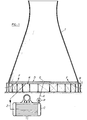
- FIG. 1 of the accompanying drawings a cooling tower T formed, as usual, a concrete veil of revolution whose circular base B of very large diameter rests, a few meters above the ground, on the periphery of a scaffolding or support frame S giving free access to a rising air flow F moved by natural draft or forced into the vast chimney that constitutes the tower T.
- the air cooler At the foot of the latter, across its base B, extends the air cooler, the essential component of which is a water distributor D represented in the form of a thin horizontal wafer of which we see in G a chute or channel from which branch offs leading to a multiplicity of sprinkler nozzles designed and arranged to cover a sprinkler zone occupying practically the entire base section of the tower traversed by the ascending air flow F.
- the non-evaporated water which falls is recovered at R and returned, by a recycling line Z, to the condenser C.
- the latter is subdivided into two sections or autonomous bodies forming separate compartments, one or the other of which may be temporarily blocked, for safety reasons and also to allow the thermal installation to continue to operate - although at reduced speed - in the event of failure or deliberate shutdown (for example for maintenance) of one of the two subdivisions of the condenser, the other remaining in service.
- the present invention overcomes the drawbacks which have just been recalled and which are subject to conventional air coolers associated with double-body condensers.
- the cooling water distribution system of the air cooler is, like the condenser, itself subdivided into two independent hydraulic circuits each having its own pump and each serving its own sprinklers.
- the nozzles belonging to the other circuit which itself remains in service are supplied for what concerns them without repercussion on their level of the stopping of the first circuit.
- the consecutive nozzles of the distributor are alternately connected to one and the other of the two hydraulic circuits to form together a nesting of nozzles of the two types in terms of supply.
- Figure 1 to which reference has been made in the preamble above is a schematic view in vertical section of a cooling tower, showing the connections of the air cooler to the condenser of the thermal installation.
- Figure 2 is a partial view in vertical section along the line II-II of Figure 3, showing the two separate hydraulic circuits for supplying the sprinkler nozzles.
- FIG. 3 is a similar view in horizontal section along the line III-III of FIG. 2.
- the single central feed chute G of the distributor D of FIG. 1 is replaced, in accordance with the present invention, by two contiguous distribution channels G1 and G2 supplied respectively from each of the two condenser bodies by two independent pumps shown diagrammatically in P1 and P2.
- the channel G1 forms a supply manifold for a series of successive branches 11 extending opposite to the channel G2 and for another series of successive branches 12 passing through the latter to go beyond.
- the channel G2 forms a supply manifold for a series of successive branches 21 situated between the branches 11 and for another series of successive branches 22 situated between the branches 12.
- the distributor D is formed by a network of interlaced pipes 11 and 21 on the one hand, 12 and 22 on the other hand, belonging alternately to the hydraulic circuit G1 and to the hydraulic circuit G2. All these ramifications serve the sprinkler nozzles of which 13 are shown those which are supplied from channel G1 and 23 which are supplied from channel G2.
- the two pumps P1, P2 each rotate and supply a distribution channel G1, G2, the system being organized so as to achieve regular dispersion of the device.
- the water is brought in by the two contiguous channels G1 and G2 on which the pipes which carry the spraying devices 13, 23 are stuck.
Landscapes
- Engineering & Computer Science (AREA)
- Mechanical Engineering (AREA)
- General Engineering & Computer Science (AREA)
- Physics & Mathematics (AREA)
- Thermal Sciences (AREA)
- Heat-Exchange Devices With Radiators And Conduit Assemblies (AREA)
- Nozzles (AREA)
Applications Claiming Priority (2)
| Application Number | Priority Date | Filing Date | Title |
|---|---|---|---|
| FR8122988 | 1981-12-09 | ||
| FR8122988A FR2517816B1 (fr) | 1981-12-09 | 1981-12-09 | Systeme de distribution d'eau de refroidissement pour aerorefrigerant |
Publications (2)
| Publication Number | Publication Date |
|---|---|
| EP0081410A1 EP0081410A1 (fr) | 1983-06-15 |
| EP0081410B1 true EP0081410B1 (fr) | 1984-09-05 |
Family
ID=9264822
Family Applications (1)
| Application Number | Title | Priority Date | Filing Date |
|---|---|---|---|
| EP82402140A Expired EP0081410B1 (fr) | 1981-12-09 | 1982-11-24 | Système de distribution d'eau de refroidissement pour aéroréfrigérant |
Country Status (7)
| Country | Link |
|---|---|
| US (1) | US4476070A (show.php) |
| EP (1) | EP0081410B1 (show.php) |
| AU (1) | AU556288B2 (show.php) |
| DE (1) | DE3260661D1 (show.php) |
| ES (1) | ES8308051A1 (show.php) |
| FR (1) | FR2517816B1 (show.php) |
| GR (1) | GR77112B (show.php) |
Families Citing this family (4)
| Publication number | Priority date | Publication date | Assignee | Title |
|---|---|---|---|---|
| AU679806B2 (en) * | 1993-12-24 | 1997-07-10 | Portland Coast Region Water Authority | Cooling tower |
| ES2116165B1 (es) * | 1994-08-05 | 1999-03-01 | Lopez De Coca Lopez De Sancho | Condensador de doble efecto. |
| IN192591B (show.php) * | 1995-12-11 | 2004-05-08 | Siemens Ag | |
| US9400140B2 (en) | 2013-06-12 | 2016-07-26 | Exxonmobil Research And Engineering Company | Cooling tower with automatic hydraulic balancing |
Family Cites Families (10)
| Publication number | Priority date | Publication date | Assignee | Title |
|---|---|---|---|---|
| BE662751A (show.php) * | ||||
| FR718790A (fr) * | 1930-10-11 | 1932-01-28 | Demag Ag | Dispositif pour économiser la force de refoulement de la masse d'eau chaude dans les tours de réfrigération à grande puissance |
| FR1109187A (fr) * | 1954-07-16 | 1956-01-23 | Anciens Etablissements R Velut | Perfectionnement aux échangeurs de chaleur en particulier aux réfrigérants de l'eau des condenseurs |
| US2979156A (en) * | 1959-05-01 | 1961-04-11 | Worthington Corp | Vacuum degasifier |
| US3318586A (en) * | 1965-01-11 | 1967-05-09 | Meredith Diven | Mass transfer unit using spaced flexible materials, and method of construction |
| DE2063828A1 (de) * | 1970-12-24 | 1972-07-06 | Kraftwerk Union Ag | Kondensationseinrichtung |
| US4032604A (en) * | 1972-09-05 | 1977-06-28 | The Marley Cooling Tower Company | Hot water supply and distribution structure for cooling towers |
| DE2452123B2 (de) * | 1974-11-02 | 1979-04-19 | Balcke-Duerr Ag, 4030 Ratingen | Kombinierter Naß-/Trockenkühlturm |
| FR2300313A1 (fr) * | 1975-02-04 | 1976-09-03 | Cem Comp Electro Mec | Refrigerant atmospherique |
| SE7709810L (sv) * | 1977-08-31 | 1979-03-01 | Munters Ab Carl | Spridarsystem for spridning av vetska, speciellt for biobeddar, kyltorn etc |
-
1981
- 1981-12-09 FR FR8122988A patent/FR2517816B1/fr not_active Expired
-
1982
- 1982-11-24 EP EP82402140A patent/EP0081410B1/fr not_active Expired
- 1982-11-24 DE DE8282402140T patent/DE3260661D1/de not_active Expired
- 1982-11-29 ES ES517767A patent/ES8308051A1/es not_active Expired
- 1982-12-01 GR GR69949A patent/GR77112B/el unknown
- 1982-12-08 AU AU91323/82A patent/AU556288B2/en not_active Ceased
- 1982-12-09 US US06/448,234 patent/US4476070A/en not_active Expired - Fee Related
Also Published As
| Publication number | Publication date |
|---|---|
| DE3260661D1 (en) | 1984-10-11 |
| GR77112B (show.php) | 1984-09-06 |
| FR2517816A1 (fr) | 1983-06-10 |
| AU9132382A (en) | 1983-06-16 |
| FR2517816B1 (fr) | 1987-05-22 |
| AU556288B2 (en) | 1986-10-30 |
| ES517767A0 (es) | 1983-08-16 |
| EP0081410A1 (fr) | 1983-06-15 |
| ES8308051A1 (es) | 1983-08-16 |
| US4476070A (en) | 1984-10-09 |
Similar Documents
| Publication | Publication Date | Title |
|---|---|---|
| US5620144A (en) | Stacked interspacial spray header for FGD wet scrubber | |
| US4634312A (en) | Self cleaning drain gutter or pipe | |
| GB1578242A (en) | Liquid sprinkling device of composite pipe type | |
| EP0081410B1 (fr) | Système de distribution d'eau de refroidissement pour aéroréfrigérant | |
| ITRM920530A0 (it) | Sistema per la distribuzione di un liquido su una superfice a mezzo diugelli di spruzzatura, ad esempio in torri di raffreddamento, condensatori ad evaporazione e simili. | |
| US5487849A (en) | Pultruded cooling tower construction | |
| US1233119A (en) | System and apparatus for spraying in cooling-ponds and the like. | |
| US9066476B2 (en) | Irrigation systems, irrigation components and related methods | |
| EP3717110B1 (en) | Modular heat exchange tower and method of assembling same | |
| JPH0532081B2 (show.php) | ||
| US3142306A (en) | Spray nozzle | |
| KR101195456B1 (ko) | 여과기능을 가진 비닐하우스용 분기관 | |
| JP4934664B2 (ja) | 灌漑装置 | |
| CN211060726U (zh) | 冷却塔喷头 | |
| FR2497466A1 (fr) | Colonne de lavage | |
| US5283012A (en) | Self-balancing hot water distribution system for multi-level cooling tower | |
| KR200221478Y1 (ko) | 안개식 방제 배관장치 | |
| US3521706A (en) | Heat exchanger with cleaning means | |
| CN107873476A (zh) | 一种能够提高用水效率的圆形喷灌机 | |
| RU2106589C1 (ru) | Блок оросителя градирни | |
| FR2658906A1 (fr) | Procede pour refroidir un liquide dans un refrigerant atmospherique et refrigerant pour la mise en óoeuvre de ce procede. | |
| RU2257933C2 (ru) | Распределительно-контактное устройство | |
| KR200173931Y1 (ko) | 농작물 살수장치 | |
| JPH0240196Y2 (show.php) | ||
| US20050210621A1 (en) | Vacuum excavation suction hose attachment |
Legal Events
| Date | Code | Title | Description |
|---|---|---|---|
| PUAI | Public reference made under article 153(3) epc to a published international application that has entered the european phase |
Free format text: ORIGINAL CODE: 0009012 |
|
| AK | Designated contracting states |
Designated state(s): BE CH DE IT LI |
|
| 17P | Request for examination filed |
Effective date: 19830824 |
|
| ITF | It: translation for a ep patent filed | ||
| GRAA | (expected) grant |
Free format text: ORIGINAL CODE: 0009210 |
|
| AK | Designated contracting states |
Designated state(s): BE CH DE IT LI |
|
| REF | Corresponds to: |
Ref document number: 3260661 Country of ref document: DE Date of ref document: 19841011 |
|
| PLBE | No opposition filed within time limit |
Free format text: ORIGINAL CODE: 0009261 |
|
| STAA | Information on the status of an ep patent application or granted ep patent |
Free format text: STATUS: NO OPPOSITION FILED WITHIN TIME LIMIT |
|
| 26N | No opposition filed | ||
| PGFP | Annual fee paid to national office [announced via postgrant information from national office to epo] |
Ref country code: CH Payment date: 19900921 Year of fee payment: 9 |
|
| PGFP | Annual fee paid to national office [announced via postgrant information from national office to epo] |
Ref country code: BE Payment date: 19900927 Year of fee payment: 9 |
|
| PGFP | Annual fee paid to national office [announced via postgrant information from national office to epo] |
Ref country code: DE Payment date: 19901029 Year of fee payment: 9 |
|
| ITTA | It: last paid annual fee | ||
| PG25 | Lapsed in a contracting state [announced via postgrant information from national office to epo] |
Ref country code: LI Effective date: 19911130 Ref country code: CH Effective date: 19911130 Ref country code: BE Effective date: 19911130 |
|
| BERE | Be: lapsed |
Owner name: CEM COMPAGNIE ELECTRO-MECANIQUE Effective date: 19911130 |
|
| REG | Reference to a national code |
Ref country code: CH Ref legal event code: PL Ref country code: CH Ref legal event code: AUV Free format text: LE BREVET CI-DESSUS EST TOMBE EN DECHEANCE FAUTE DE PAIEMENT, DE LA 10E ANNUITE. |
|
| PG25 | Lapsed in a contracting state [announced via postgrant information from national office to epo] |
Ref country code: DE Effective date: 19920801 |