EP0081274B1 - Implement for loosening soil - Google Patents
Implement for loosening soil Download PDFInfo
- Publication number
- EP0081274B1 EP0081274B1 EP82201656A EP82201656A EP0081274B1 EP 0081274 B1 EP0081274 B1 EP 0081274B1 EP 82201656 A EP82201656 A EP 82201656A EP 82201656 A EP82201656 A EP 82201656A EP 0081274 B1 EP0081274 B1 EP 0081274B1
- Authority
- EP
- European Patent Office
- Prior art keywords
- soil
- blade
- cultivating implement
- blades
- frame
- Prior art date
- Legal status (The legal status is an assumption and is not a legal conclusion. Google has not performed a legal analysis and makes no representation as to the accuracy of the status listed.)
- Expired
Links
Images


Classifications
-
- E—FIXED CONSTRUCTIONS
- E02—HYDRAULIC ENGINEERING; FOUNDATIONS; SOIL SHIFTING
- E02F—DREDGING; SOIL-SHIFTING
- E02F5/00—Dredgers or soil-shifting machines for special purposes
- E02F5/02—Dredgers or soil-shifting machines for special purposes for digging trenches or ditches
- E02F5/10—Dredgers or soil-shifting machines for special purposes for digging trenches or ditches with arrangements for reinforcing trenches or ditches; with arrangements for making or assembling conduits or for laying conduits or cables
- E02F5/102—Dredgers or soil-shifting machines for special purposes for digging trenches or ditches with arrangements for reinforcing trenches or ditches; with arrangements for making or assembling conduits or for laying conduits or cables operatively associated with mole-ploughs, coulters
-
- A—HUMAN NECESSITIES
- A01—AGRICULTURE; FORESTRY; ANIMAL HUSBANDRY; HUNTING; TRAPPING; FISHING
- A01B—SOIL WORKING IN AGRICULTURE OR FORESTRY; PARTS, DETAILS, OR ACCESSORIES OF AGRICULTURAL MACHINES OR IMPLEMENTS, IN GENERAL
- A01B13/00—Ploughs or like machines for special purposes ; Ditch diggers, trench ploughs, forestry ploughs, ploughs for land or marsh reclamation
- A01B13/08—Ploughs or like machines for special purposes ; Ditch diggers, trench ploughs, forestry ploughs, ploughs for land or marsh reclamation for working subsoil
-
- A—HUMAN NECESSITIES
- A01—AGRICULTURE; FORESTRY; ANIMAL HUSBANDRY; HUNTING; TRAPPING; FISHING
- A01B—SOIL WORKING IN AGRICULTURE OR FORESTRY; PARTS, DETAILS, OR ACCESSORIES OF AGRICULTURAL MACHINES OR IMPLEMENTS, IN GENERAL
- A01B79/00—Methods for working soil
- A01B79/02—Methods for working soil combined with other agricultural processing, e.g. fertilising, planting
Definitions
- This invention relates to an improved agronomic implement. More specifically, it relates to an improved implement for preparing the soil prior to growing crops.
- ploughing uses substantial amounts of energy, in principle unnecessarily, in turning over the soil. Millions of tons of earth are lifted and inverted by the plough every year, using in nearly every case tractors powered by petroleum-based fuels, a non-renewable resource.
- Seed-drills capable of making a seed-furrow in untilled ground had to be designed (see for example UK Patents Nos. 1150723 and 1274219) and manufactured; and the limitations of the technique explored, so as to be able to predict when the technique would work and when it would fail. This development has been succeeded by widespread adoption of the technique in the 1970's, with savings to farmers in fuel, in manpower and in time.
- UK Patent No. 1,493,346 describes a sub-soil breaking soil cultivation implement comprising one or more blades extending downwardly and sideways into the soil and having a leading cutting edge (preferably sloped forwardly and downwardly) which is bevelled to raise soil over the blade and to avoid compression of soil under the blade as it cuts.
- the invention is described for use in the improvement of grassland, or in the improvement of arable land in conjunction with the plough, or for use in establishing drainage channels which are simultaneously filled with sand, or for use in laying flexible pipe.
- the device of UK Patent No. 1,493,346 may be used in not very heavy soils which are fairly dry and friable, provided the blades are mounted parallel to the direction of forward motion of the vehicle impelling them. Then, provided the soil is of just the right type, the blade causes just sufficient break-up of the soil to improve porosity without substantially disturbing the surface, and subsequent drilling can be carried out effectively in accordance with the invention.
- the blade so set will not break up the soil sufficiently. Attempts have been made to increase break-up by setting the plane of the blades at a slight angle to the direction of forward motion, so as to increase the displacement of the soil by the blades. This however has generally proved impractical. The slight divergence between the plane of the blades and the direction of forward motion considerably increases the load on the tractor and moreover drags it off course. Also, the blades may bend, and if made thicker to avoid this, disturb the soil surface unduly.
- Australian Patent No. 11398/76 describes a sub-soil cultivation implement comprising a blade, as a soil working tool, which, in operation, extends downwardly into the soil, the lower end of the blade being provided with a "shoe member” (referred to as a bar 49) having an upwardly and rearwardly inclined surface at its leading edge.
- the "shoe member” (the bar 49) is, however, of circular or triangular cross section. Neither of these two shapes is effective in reducing undesirable sideways movement of the implement in the soil in operation.
- the emphasis in the device described in Australian Patent No. 11398/76 is on mole-ploughing which demands easy passage of the "shoe member" (the bar 49) through the soil; the bar is dimensioned, and shaped, accordingly.
- the present invention provides a cultivating implement comprising mounting means and at least one soil working tool mounted thereon including a blade which, in operation, extends downwardly into the soil in a plane substantially parallel to its direction of travel edgewise through the soil said plane being inclined at an acute angle to the vertical, the tool having at the lower end of the inclined inclined blade a shoe member having an upwardly and rearwardly inclined upper surface at its leading end characterised in that the shoe member has an upright and rearwardly extending, side surface, said side surface being substantially planar.
- the blade has an extension, eg. a flap, pivotally connected at the trailing edge of the blade and adjustable, for example, by a screw.
- the trailing edge of the flap may carry rearwardly projecting rods or knives.
- the extension may also be a roller.
- the blade is preferably supported on the mounting means so as to have its plane substantially parallel to the direction of its movement through the soil when in use.
- the mounting means is preferably constructed so as to be detachably connectable to a vehicle.
- the soil working tool preferably comprises a generally flat earth-cutting blade, supported by mounting means for carrying it on a vehicle and adapted, for example by hydraulic or other powered mechanism, to lower it into the soil and, preferably aided by an adjustable depth wheel running over the ground surface and secured to the mounting means, hold it in an operative position for movement through the soil by traction from the vehicle, with the leading edge of the blade sloping forwardly and the plane of the blade sloping sideways and downwardly so as to make a diagonal cut in the soil, the leading edge being bevelled on its upper surface so as to lift soil over the blade as it passes through, without compacting it beneath the blade.
- the blade in the operative position is supported with its plane parallel to the direction of motion of the vehicle, and is preferably provided with a hinged extension (eg. a flap) at its trailing edge which is adjustable between a position substantially directly behind the blade and a projecting position which increases the displacement of soil passing above the blade.
- the tool comprises a gang of such blades mounted adjacently, in rank or in echelon; and preferably each blade in the gang is mounted with its bottom edge approximately vertically below the top edge of its neighbour.
- a degree of vibration of the blades can, if desired, be provided.
- a flat, flexible cutting disc in front of each blade is independently mounted a flat, flexible cutting disc, the plane thereof lying in the same plane as the blade behind it.
- Such discs are preferably pivotally mounted on the mounting means, eg. framework, carrying the blades, and are loaded, egby spring action. Preferably they are fitted with scrapers.
- the tool of the invention may further be provided with rollers, eg. crumble rollers, located between adjacent blades, such crumble rollers not having a continuous arcuate surface but consisting of a plurality of parallel or spirally arranged rods or bars disposed in a circumference, as viewed from the side, so as to present, as it were, an interrupted roller surface.
- rollers eg. crumble rollers
- such a roller, or crumble roller is disposed in such a position relative to the blades, that the surface or the rods or bars successively impact upon and/or exert pressure on the soil at a point above or just rearward of the trailing edge of the hinged extension (flap) of the blade.
- angled blades mounted on rotatable shafts may be deployed to provide further fissuring of the soil structure downwardly from above ground level.
- These shafts are preferably biassed towards the soil eg. by springs and the same applies to the crumble rollers.
- Both rollers and cutting knive shafts can be friction driven, or power driven from the power take-off shaft of the tractor pulling the tool or device.
- the axes of the crumble rollers or shafts are preferably disposed to lie horizontally of the soil surface and at right angles to the direction of pull of the tool or device as a whole.
- a tool of this type may be used to improve soil porosity in many types of soil, without substantial disturbance of the soil surface. Provided the displacement of the hinged extension is appropriate to the soil type, the load on the tractor is not excessive, nor is it diverted from its course, but nevertheless an appropriate degree of soil fissuring may be obtained.
- the (or each) blade is preferably of uniform thickness over its working surface, though it may, if desired, increase somewhat in thickness from upper to lower edge, or vice versa, or from front to rear.
- Its lower edge is preferably horizontal in the operative position, and carries a shoe member projecting forwardly and downwardly where the lower and leading edges meet. This shoe helps to draw the blade down into the soil.
- the hinged extension which may be fitted to the trailing edge of the blade may be of various kinds. It may be a simple flap in the shape of a rectangle or parallelogram, one of its longer sides being hinged along the trailing edge of the blade. It may be a flap in the shape of a triangle or trapezium, preferably increasing in width towards the lower edge of the blade. It may be mounted along the whole of the trailing edge, or along part only, preferably the part adjacent the lower edge.
- Possible forms of extension other than simple flaps include rollers; flaps bearing backwardly- projecting rods or knives; and flaps which are distorted upwardly (in the operative position) adjacent the lower edge of the blade.
- More than one extension may be mounted, one above the other.
- the blades may be hollow and holed to serve as distributors for liquid fertiliser during fissuring.
- separate fertiliser distributing tubes may be used, for example located between, or behind, the blade and its rear flap or roller. These tubes may be perforated. If desired these tubes, or further tubes, may be used to introduce materials into the fissures which will, or can be made to, explode to provide further disruption of the soil structure.
- a parallel- sided blade 1 is shown fastened by bolts 11 to an elbow 12, the other end of which is secured to a collar 13 mounted for rotation on a transverse bar 14 carried by a tractor (not shown).
- the elbow 12 projects sideways at about 45° to the axis of bar 14, holding the blade 1 at the same angle.
- the elbow also orients the blade 1 in the fore-and-aft position so that its sides are closely aligned with the forward motion of the tractor.
- the blade 1 has parallel edges, the upper and lower edges 7 and 8 being horizontal and the leading and trailing edges 9 and 10 sloping forwardly and downwardly.
- the leading edge 9 is provided with a downwardly sloping bevel 6 which terminates in a sharp soil-cutting edge, and serves as a soil-lifting surface.
- the lower edge 8 is fitted with a shoe 3, the front of which is turned downwards to form a nose 15 terminating in a cutting edge.
- the trailing edge 10 is provided with hasps 16, meshing with hasps 17 of an extension flap 2.
- a steel rod 18 passes through hasps 16 and 17 and serves as pivot for the flap 2.
- a stop 4 is fastened by a bolt 50 on the lower side near the top of trailing edge 10; this carries a grubscrew 5 which abuts the flap 2.
- flap 2 is shown substantially parallel to the blade 1, but by screwing in screw 5 it can be slanted out of the plane of the blade 1 to a greater or lesser degree.
- FIGS 3 and 4 show the same type of blade fitted with an alternative form of extension.
- Blade 1, shoe 3 and steel pivot rod 18 are as before; but flap 2 is replaced by flap 27, carrying two short knives 28 and two longer knives 29 projecting backwards in the plane of the flap 27.
- the flap 27 is adjusted, in the same way as the flap 2, by stop 4 and grubscrew 5.
- Figures 5 and 6 show the same type of blade as before fitted with an alternative extension 59. This is flat but non-uniform in outline, with a narrow projecting bar 30 at the top followed by a steady increase in depth down the flap. It is adjusted in the same way as before.
- Figures 7 and 8 show the same type of blade as before fitted with an alternative extension 3. This is flat over most of its length, but curves upwards out of the plane towards its lower end. It is adjustable as before.
- Figures 9 and 10 show a blade of the same type as before fitted with an extension 32 carrying a roller 33.
- the extension is mounted on the blade in the same way as before, but carries two arms 34, 35 at its upper and lower ends between which a roller 33 in the form of a right cylinder is mounted for free rotation on a steel rod 36.
- the angle of the extension 32 is adjustable by stop 4 and screw 5 as before.
- Figure 11 shows a blade and extension as in figures 9 and 10, but the roller 33 has been replaced by a roller 37 of gently tapering frustroconical form, mounted with its thicker end downwards. Its attitude is adjustable in the same way as before.
- Figure 12 shows a gang 40 of three blades, of the type shown in figures 1 and 2, mounted on a tractor 43.
- the gang 40 is rotated upwardly about the bar 14 by a hydraulic ram 41 until the lower edges 8 of the blades 1 are vertical.
- the screws 5 on each blade are adjusted to set the flaps 2 at the angle appropriate to the soil being worked (the heavier the soil, the larger the angle).
- the ram 41 lowers blades 1 into a position in which the noses 15 dig into the earth.
- the tractor then moves forward, and the blades 1 are forced into the soil by the combined action of the ram 41 and the soil acting on the noses 15 and shoes 3.
- the blades 1 cut diagonally through the soil, lifting the soil over their upper sides, without significant compression on the under sides.
- the total amount of lifting depends on the degree of which the flaps 2 are cocked up, and by this means the degree of fissuring in the soil is controlled as required.
- the surface of the land lifts up and subsides like a wave, but apart from parallel trenches along the lines of entry of the blades 1, the surface of the soil is afterwards remarkably free from disturbance.
- Figure 13 shows a crumble roller having circular side plates 44 having mounting shafts 45 and cross bars 46 for pressing upon the soil surface.
- Figure 14 shows three crumble rollers mounted so as to operate in conjunction with the blades 1 of the device illustrated in Figure 12.
- the shafts 45 are rotatably mounted on the elbows 12 by way of extension arms (not shown) therefrom.
- the shafts 45 are rotatably mounted on arms extending separately from the transverse bar 14 or from another frame member of the tool. The action of the crumble rollers is to further disrupt and break up the soil structure near the soil surface, where there may be trash and/or matted roots or compression of the soil by animal hooves.
- Figure 15 shows a pair of cutting rollers 47 with angled blades 48 disposed circumferentially around shafts 49.
- a pair of these rollers may be deployed in the place of a crumble roller.
- the shafts 49 are rotatable and may be friction driven by contact with the soil surface; or they may be rotated by a suitable mechanical linkage (not shown) from the power take-off shaft of the tractor.
- the blades of the second cutting roller are angled in a different direction to those of the first roller and the shafts 49 can be variably biassed, for example by spring loading, so that the blades are forced into the soil to a greater or lesser degree depending upon the required amount of penetration of the soil.
- stop and grubscrew shown could be used to set or control the angle of the extensions to the blades. It is particularly convenient to do this by hydraulic means, because all blades could then be set simultaneously by the touch of a button (rather than individually by hand as in the device illustrated). This may even be done while the device is being operated in a field; if the soil type is different in different parts of the field.
- Figures 16, 17, 18 and 19 show a further implement according to the invention.
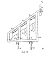
- the plan view of Figure 16 shows three blades 52, 53, 54 mounted on a framework 51 of metal girders and are bolted to girders 55, 56, 57 thereof.
- the framework 51 has two bars 58, 59 for connection to a tractor (not shown).
- Discs 60, 61, 62 are located in front of the blades and are mounted on the girders 55, 56, 57 by a mechanism (not shown) which is illustrated in detail in Figures 18 and 19.
- a ground or depth wheel 63 which is adjustable in height by a raising and lowering mechanism 64 ( Figure 17) is set to regulate the depth to which the blades penetrate below the soil surface when the device is in use.
- Figure 17 shows the implement of Figure 16 in side elevation viewed on the line I-I of Figure 16.
- the slit cutting discs 60, 61, 62 lie in substantially the same plane as the blades 52, 53, 54 and in use the discs cut a slit in the soil which assists the penetration and movement of the fissuring blades onto, and through, the soil.
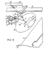
- Figures 18 and 19 show, in enlarged fashion, blade 52 and its associated disc 60 and illustrate mechanisms for the mounting of the discs on the framework 51 of the implement.
- a cranked rod 65 is adjustably held at one end by a clamp 66 to the girder 55 and to its other end is pivotally clamped a second clamp 67 having an integral abutment 68 in which is pivotally mounted an elongated flat metal bar 69.
- the clamp 67 and abutment 68 can pivot around the bar 65 in a bush 70 and the bar 69 can pivot around the abutment 68 in a bush 72.
- a rubber disc 71 Interposed between 68 and 69 is a rubber disc 71 to provide a cushioning resilience between them. Pivotal movement of the elongated flat bar 69 in the bush 72 is restricted by a pin 73 attached to the bar lying within a trough on the clamp 67 having raised edges 74, 75 which act as stops.
- Pivotal movement of the elongated bar 69 (by pivoting of the clamp 67 about the rod 65 in the bush 70) in the plane at right angles to the foregoing plane of pivotal movement is restricted by a retaining spring 76 extending between a loop 77 on the bar 69 and an attachment loop 78 to the girder 56, that is the girder adjacent to the girder 55 and on which is mounted the adjacent blade 53.
- the flat, flexible, metal disc 79 which is rotatably mounted by a bush 80 on the elongated bar 69, is enabled to pivot bodily to a limited degree in two planes at right angles to each other.
- the first of these planes is the plane in which the disc itself normally lies (and the associated blade) and the other is at right angles to this.
- the disc 79 is equipped with a scraper 81 which is pressed against the surface of the disc by a spring concealed within its point of pivotal attachment 82 to a cranked extension 83 of the elongated bar 69.
- the implement shown in Figures 15, 16, 17, 18 and 19 may incorporate one or more rollers of the kind hereinbefore described, for example as shown in Figure 13, or one or more pairs of shafts with rotating cutting knives, for example as shown in Figure 15. It may also use any of, or any combination of the blades shown in Figures 1, 2, 3,4,5,6,7,8,9, 10 or 11.
Landscapes
- Engineering & Computer Science (AREA)
- Life Sciences & Earth Sciences (AREA)
- Mechanical Engineering (AREA)
- Soil Sciences (AREA)
- Environmental Sciences (AREA)
- Mining & Mineral Resources (AREA)
- Civil Engineering (AREA)
- General Engineering & Computer Science (AREA)
- Structural Engineering (AREA)
- Soil Working Implements (AREA)
- Catching Or Destruction (AREA)
Description
- This invention relates to an improved agronomic implement. More specifically, it relates to an improved implement for preparing the soil prior to growing crops.
- For hundreds of years, agricultural land has been prepared for the sowing of seed by the use of the mouldboard plough. The prime function of the plough is to kill weeds; but it also can have the effect of breaking up the soil, making it less compact, and creating a tilth in which seeds may be buried. Generally ploughing is followed by further operations for breaking up the soil, eg. discing and harrowing, prior to sowing. However, ploughing uses substantial amounts of energy, in principle unnecessarily, in turning over the soil. Millions of tons of earth are lifted and inverted by the plough every year, using in nearly every case tractors powered by petroleum-based fuels, a non-renewable resource.
- In the 1950's the discovery of the herbicide paraquat opened the way to novel methods of establishing crops, without the use of the plough. Paraquat was the first herbicide (killing all green growth) to be discovered which was totally inactivated in contact with the soil. Experiments with this new herbicide showed that it could replace the weed-killing function of the plough: that stubble or grassland could be sprayed with paraquat; and shortly thereafter seed could be drilled direct into the uncultivated ground; and that, in suitable circumstances, such seed would germinate as well as (sometimes better than) seed planted in ploughed land after conventional tilling techniques. During the 1960's this technique of "direct drilling" was developed for use in agriculture. Seed-drills capable of making a seed-furrow in untilled ground had to be designed (see for example UK Patents Nos. 1150723 and 1274219) and manufactured; and the limitations of the technique explored, so as to be able to predict when the technique would work and when it would fail. This development has been succeeded by widespread adoption of the technique in the 1970's, with savings to farmers in fuel, in manpower and in time.
- One limitation of the technique as it has been practised up to now is the type of soil on which it can be used. For success, the soil must have drainage, good structure and be uncompacted. On heavy land, the grooves cut for the seed by the drills frequently become waterlogged, and establishment of seed is patchy. Much agricultural land (over half the land farmed in Britain today) is not suitable for the direct drilling technique. Land may also, by the passage of heavy machinery, become too compacted to be suitable for the technique.
- It is an object of the present invention to provide an improved implement for use in soil loosening processes.
- UK Patent No. 1,493,346 describes a sub-soil breaking soil cultivation implement comprising one or more blades extending downwardly and sideways into the soil and having a leading cutting edge (preferably sloped forwardly and downwardly) which is bevelled to raise soil over the blade and to avoid compression of soil under the blade as it cuts. The invention is described for use in the improvement of grassland, or in the improvement of arable land in conjunction with the plough, or for use in establishing drainage channels which are simultaneously filled with sand, or for use in laying flexible pipe.
- The device of UK Patent No. 1,493,346 may be used in not very heavy soils which are fairly dry and friable, provided the blades are mounted parallel to the direction of forward motion of the vehicle impelling them. Then, provided the soil is of just the right type, the blade causes just sufficient break-up of the soil to improve porosity without substantially disturbing the surface, and subsequent drilling can be carried out effectively in accordance with the invention. However, on many heavier and less friable soils, the blade so set will not break up the soil sufficiently. Attempts have been made to increase break-up by setting the plane of the blades at a slight angle to the direction of forward motion, so as to increase the displacement of the soil by the blades. This however has generally proved impractical. The slight divergence between the plane of the blades and the direction of forward motion considerably increases the load on the tractor and moreover drags it off course. Also, the blades may bend, and if made thicker to avoid this, disturb the soil surface unduly.
- Australian Patent No. 11398/76 describes a sub-soil cultivation implement comprising a blade, as a soil working tool, which, in operation, extends downwardly into the soil, the lower end of the blade being provided with a "shoe member" (referred to as a bar 49) having an upwardly and rearwardly inclined surface at its leading edge. The "shoe member" (the bar 49) is, however, of circular or triangular cross section. Neither of these two shapes is effective in reducing undesirable sideways movement of the implement in the soil in operation. The emphasis in the device described in Australian Patent No. 11398/76 is on mole-ploughing which demands easy passage of the "shoe member" (the bar 49) through the soil; the bar is dimensioned, and shaped, accordingly.
- Accordingly, we have devised an improved implement which can be satisfactorily employed in various types of heavy or compacted soil with differing moisture content.
- The present invention provides a cultivating implement comprising mounting means and at least one soil working tool mounted thereon including a blade which, in operation, extends downwardly into the soil in a plane substantially parallel to its direction of travel edgewise through the soil said plane being inclined at an acute angle to the vertical, the tool having at the lower end of the inclined inclined blade a shoe member having an upwardly and rearwardly inclined upper surface at its leading end characterised in that the shoe member has an upright and rearwardly extending, side surface, said side surface being substantially planar.
- Preferably the blade has an extension, eg. a flap, pivotally connected at the trailing edge of the blade and adjustable, for example, by a screw. The trailing edge of the flap may carry rearwardly projecting rods or knives.
- The extension may also be a roller.
- The blade is preferably supported on the mounting means so as to have its plane substantially parallel to the direction of its movement through the soil when in use. By this means compaction of the soil beneath the blade as it travels through the soil is very substantially reduced.
- The mounting means is preferably constructed so as to be detachably connectable to a vehicle.
- The soil working tool preferably comprises a generally flat earth-cutting blade, supported by mounting means for carrying it on a vehicle and adapted, for example by hydraulic or other powered mechanism, to lower it into the soil and, preferably aided by an adjustable depth wheel running over the ground surface and secured to the mounting means, hold it in an operative position for movement through the soil by traction from the vehicle, with the leading edge of the blade sloping forwardly and the plane of the blade sloping sideways and downwardly so as to make a diagonal cut in the soil, the leading edge being bevelled on its upper surface so as to lift soil over the blade as it passes through, without compacting it beneath the blade. The blade in the operative position is supported with its plane parallel to the direction of motion of the vehicle, and is preferably provided with a hinged extension (eg. a flap) at its trailing edge which is adjustable between a position substantially directly behind the blade and a projecting position which increases the displacement of soil passing above the blade. Preferably the tool comprises a gang of such blades mounted adjacently, in rank or in echelon; and preferably each blade in the gang is mounted with its bottom edge approximately vertically below the top edge of its neighbour. A degree of vibration of the blades can, if desired, be provided. Preferably, also, in front of each blade is independently mounted a flat, flexible cutting disc, the plane thereof lying in the same plane as the blade behind it. Such discs are preferably pivotally mounted on the mounting means, eg. framework, carrying the blades, and are loaded, egby spring action. Preferably they are fitted with scrapers.
- As an optional feature the tool of the invention may further be provided with rollers, eg. crumble rollers, located between adjacent blades, such crumble rollers not having a continuous arcuate surface but consisting of a plurality of parallel or spirally arranged rods or bars disposed in a circumference, as viewed from the side, so as to present, as it were, an interrupted roller surface. Preferably such a roller, or crumble roller, is disposed in such a position relative to the blades, that the surface or the rods or bars successively impact upon and/or exert pressure on the soil at a point above or just rearward of the trailing edge of the hinged extension (flap) of the blade. As an alternative to crumble rollers, angled blades mounted on rotatable shafts may be deployed to provide further fissuring of the soil structure downwardly from above ground level. These shafts are preferably biassed towards the soil eg. by springs and the same applies to the crumble rollers. Both rollers and cutting knive shafts can be friction driven, or power driven from the power take-off shaft of the tractor pulling the tool or device. The axes of the crumble rollers or shafts are preferably disposed to lie horizontally of the soil surface and at right angles to the direction of pull of the tool or device as a whole.
- It is found that a tool of this type may be used to improve soil porosity in many types of soil, without substantial disturbance of the soil surface. Provided the displacement of the hinged extension is appropriate to the soil type, the load on the tractor is not excessive, nor is it diverted from its course, but nevertheless an appropriate degree of soil fissuring may be obtained.
- The (or each) blade is preferably of uniform thickness over its working surface, though it may, if desired, increase somewhat in thickness from upper to lower edge, or vice versa, or from front to rear. Its lower edge is preferably horizontal in the operative position, and carries a shoe member projecting forwardly and downwardly where the lower and leading edges meet. This shoe helps to draw the blade down into the soil.
- The hinged extension which may be fitted to the trailing edge of the blade may be of various kinds. It may be a simple flap in the shape of a rectangle or parallelogram, one of its longer sides being hinged along the trailing edge of the blade. It may be a flap in the shape of a triangle or trapezium, preferably increasing in width towards the lower edge of the blade. It may be mounted along the whole of the trailing edge, or along part only, preferably the part adjacent the lower edge.
- Possible forms of extension other than simple flaps include rollers; flaps bearing backwardly- projecting rods or knives; and flaps which are distorted upwardly (in the operative position) adjacent the lower edge of the blade.
- More than one extension may be mounted, one above the other.
- The blades may be hollow and holed to serve as distributors for liquid fertiliser during fissuring. Alternatively separate fertiliser distributing tubes may be used, for example located between, or behind, the blade and its rear flap or roller. These tubes may be perforated. If desired these tubes, or further tubes, may be used to introduce materials into the fissures which will, or can be made to, explode to provide further disruption of the soil structure.
- Embodiments of the invention will now be described with reference to the drawings, in which:
- Figure 1 is a side view of a blade for use in the invention shown with operative position, mounted on a tractor drawbar;
- Figure 2 is a top view of the blade of Figure 1, viewed edgewise to the plane of the blade;
- Figure 3 is a side view of a blade with a second type of extension;
- Figure 4 is a top edgewise view of the blade of figure 3.
- Figure 5 is a side view of a blade with a third type of extension;
- Figure 6 is a top edgewise view of the blade of figure 5.
- Figure 7 is a side view of a blade with a fourth type of extension.
- Figure 8 is an end view of the extension shown in figure 7.
- Figure 9 is a side view of a blade with an extension in the form of a roller.
- Figure 10 is a top edgewise view of the blade of figure 9.
- Figure 11 is a side view of a blade with a different roller extension.
- Figure 12 is a rear view of a gang of blades of the kind shown in Figures 1 and 2 being drawn through the soil.
- Figure 13 is a perspective view of a crumble roller.
- Figure 14 is a rear view of a gang of blades with crumble rollers of the kind shown in Figure 13 disposed between adjacent blades.
- Figure 15 is a plan view of a pair of rotatable cutting rollers with blades which may be used in the place of a crumble roller.
- Figure 16 is illustrative of a further embodiment of the invention and shows, schematically in plan view, an implement having an arrangement on a framework of blades of the kind shown in figures 1 and 2 but with modified, slimmer, and more sharply pointed nose and shoe portion to each 'blade'.
- Figure 17 is a side elevation of the implement shown in Figure 16 on the line I-I thereof.
- Figure 18 is a larger scale view of a blade and disc as illustrated in Figure 17 and shows details of an assembly for mounting the disc upon the implement framework.
- Figure 19 is a view similar to that of Figure 18 but from the opposite side to the side used in Figure 18.
- With reference to Figures 1 and 2, a parallel-
sided blade 1 is shown fastened bybolts 11 to anelbow 12, the other end of which is secured to acollar 13 mounted for rotation on atransverse bar 14 carried by a tractor (not shown). Theelbow 12 projects sideways at about 45° to the axis ofbar 14, holding theblade 1 at the same angle. The elbow also orients theblade 1 in the fore-and-aft position so that its sides are closely aligned with the forward motion of the tractor. Theblade 1 has parallel edges, the upper andlower edges edges 9 and 10 sloping forwardly and downwardly. The leading edge 9 is provided with a downwardly slopingbevel 6 which terminates in a sharp soil-cutting edge, and serves as a soil-lifting surface. Thelower edge 8 is fitted with ashoe 3, the front of which is turned downwards to form anose 15 terminating in a cutting edge. The trailingedge 10 is provided withhasps 16, meshing withhasps 17 of anextension flap 2. Asteel rod 18 passes throughhasps flap 2. Astop 4 is fastened by abolt 50 on the lower side near the top of trailingedge 10; this carries agrubscrew 5 which abuts theflap 2. In figures 1 and 2flap 2 is shown substantially parallel to theblade 1, but by screwing inscrew 5 it can be slanted out of the plane of theblade 1 to a greater or lesser degree. - Figures 3 and 4 show the same type of blade fitted with an alternative form of extension.
Blade 1,shoe 3 andsteel pivot rod 18 are as before; butflap 2 is replaced byflap 27, carrying twoshort knives 28 and twolonger knives 29 projecting backwards in the plane of theflap 27. Theflap 27 is adjusted, in the same way as theflap 2, bystop 4 andgrubscrew 5. - Figures 5 and 6 show the same type of blade as before fitted with an
alternative extension 59. This is flat but non-uniform in outline, with a narrow projectingbar 30 at the top followed by a steady increase in depth down the flap. It is adjusted in the same way as before. - Figures 7 and 8 show the same type of blade as before fitted with an
alternative extension 3. This is flat over most of its length, but curves upwards out of the plane towards its lower end. It is adjustable as before. - Figures 9 and 10 show a blade of the same type as before fitted with an
extension 32 carrying aroller 33. The extension is mounted on the blade in the same way as before, but carries twoarms roller 33 in the form of a right cylinder is mounted for free rotation on asteel rod 36. The angle of theextension 32 is adjustable bystop 4 andscrew 5 as before. - Figure 11 shows a blade and extension as in figures 9 and 10, but the
roller 33 has been replaced by a roller 37 of gently tapering frustroconical form, mounted with its thicker end downwards. Its attitude is adjustable in the same way as before. - The use of the device will now be described with particular reference to figures 1, 2 and 12.
- Figure 12 shows a
gang 40 of three blades, of the type shown in figures 1 and 2, mounted on atractor 43. For transport, thegang 40 is rotated upwardly about thebar 14 by a hydraulic ram 41 until thelower edges 8 of theblades 1 are vertical. Thescrews 5 on each blade are adjusted to set theflaps 2 at the angle appropriate to the soil being worked (the heavier the soil, the larger the angle). When thetractor 43 is positioned to begin working, the ram 41 lowersblades 1 into a position in which thenoses 15 dig into the earth. - The tractor then moves forward, and the
blades 1 are forced into the soil by the combined action of the ram 41 and the soil acting on thenoses 15 and shoes 3. In the operative position theblades 1 cut diagonally through the soil, lifting the soil over their upper sides, without significant compression on the under sides. The total amount of lifting depends on the degree of which theflaps 2 are cocked up, and by this means the degree of fissuring in the soil is controlled as required. As the tool is carried along, the surface of the land lifts up and subsides like a wave, but apart from parallel trenches along the lines of entry of theblades 1, the surface of the soil is afterwards remarkably free from disturbance. - Figure 13 shows a crumble roller having
circular side plates 44 having mountingshafts 45 and cross bars 46 for pressing upon the soil surface. - Figure 14 shows three crumble rollers mounted so as to operate in conjunction with the
blades 1 of the device illustrated in Figure 12. Theshafts 45 are rotatably mounted on theelbows 12 by way of extension arms (not shown) therefrom. In an alternative embodiment (not shown) theshafts 45 are rotatably mounted on arms extending separately from thetransverse bar 14 or from another frame member of the tool. The action of the crumble rollers is to further disrupt and break up the soil structure near the soil surface, where there may be trash and/or matted roots or compression of the soil by animal hooves. - Figure 15 shows a pair of cutting rollers 47 with angled blades 48 disposed circumferentially around
shafts 49. A pair of these rollers may be deployed in the place of a crumble roller. Theshafts 49 are rotatable and may be friction driven by contact with the soil surface; or they may be rotated by a suitable mechanical linkage (not shown) from the power take-off shaft of the tractor. The blades of the second cutting roller are angled in a different direction to those of the first roller and theshafts 49 can be variably biassed, for example by spring loading, so that the blades are forced into the soil to a greater or lesser degree depending upon the required amount of penetration of the soil. - Instead of the blade and extension shown in Figures 1 and 2, those shown in each of Figures 3 and 4, 5 and 6, 7 and 8, 9 and 10, and 11 may be used instead. The extension of figures 3 and 4 increases break-up of the soil when the extension is set at an angle, through the cutting action of projecting knives. The extensions shown in figures 5 and 6, and in 7 and 8, both project further the deeper they are in the soil, so that the soil is disturbed more at a greater depth. The rollers of figures 9 and 10, and 11 roll against the soil above (rather than the soil below, which they are not forced into contact with) thereby usefully reducing the drag on the tractor. The frustroconical roller of figure 11, like the extensions of figures 5-8, disturbs the soil at greater depths.
- Instead of the stop and grubscrew shown, other devices could be used to set or control the angle of the extensions to the blades. It is particularly convenient to do this by hydraulic means, because all blades could then be set simultaneously by the touch of a button (rather than individually by hand as in the device illustrated). This may even be done while the device is being operated in a field; if the soil type is different in different parts of the field.
- Figures 16, 17, 18 and 19 show a further implement according to the invention. In this device, the plan view of Figure 16 shows three
blades framework 51 of metal girders and are bolted togirders framework 51 has twobars Discs girders depth wheel 63, which is adjustable in height by a raising and lowering mechanism 64 (Figure 17) is set to regulate the depth to which the blades penetrate below the soil surface when the device is in use. - Figure 17 shows the implement of Figure 16 in side elevation viewed on the line I-I of Figure 16. The
slit cutting discs blades - Figures 18 and 19 show, in enlarged fashion,
blade 52 and its associated disc 60 and illustrate mechanisms for the mounting of the discs on theframework 51 of the implement. A crankedrod 65 is adjustably held at one end by aclamp 66 to thegirder 55 and to its other end is pivotally clamped asecond clamp 67 having anintegral abutment 68 in which is pivotally mounted an elongatedflat metal bar 69. Theclamp 67 andabutment 68 can pivot around thebar 65 in abush 70 and thebar 69 can pivot around theabutment 68 in abush 72. - Interposed between 68 and 69 is a
rubber disc 71 to provide a cushioning resilience between them. Pivotal movement of the elongatedflat bar 69 in thebush 72 is restricted by apin 73 attached to the bar lying within a trough on theclamp 67 having raisededges - Pivotal movement of the elongated bar 69 (by pivoting of the
clamp 67 about therod 65 in the bush 70) in the plane at right angles to the foregoing plane of pivotal movement is restricted by a retainingspring 76 extending between aloop 77 on thebar 69 and anattachment loop 78 to thegirder 56, that is the girder adjacent to thegirder 55 and on which is mounted theadjacent blade 53. - By this mechanism the flat, flexible,
metal disc 79, which is rotatably mounted by abush 80 on theelongated bar 69, is enabled to pivot bodily to a limited degree in two planes at right angles to each other. The first of these planes is the plane in which the disc itself normally lies (and the associated blade) and the other is at right angles to this. These degrees of freedom of movement assist the disc in penetrating and cutting through the soil without damage to its edges or mounting, eg. by stones or other obstacles. - The
disc 79 is equipped with ascraper 81 which is pressed against the surface of the disc by a spring concealed within its point ofpivotal attachment 82 to a crankedextension 83 of theelongated bar 69. - The implement shown in Figures 15, 16, 17, 18 and 19 may incorporate one or more rollers of the kind hereinbefore described, for example as shown in Figure 13, or one or more pairs of shafts with rotating cutting knives, for example as shown in Figure 15. It may also use any of, or any combination of the blades shown in Figures 1, 2, 3,4,5,6,7,8,9, 10 or 11.
Claims (8)
Applications Claiming Priority (4)
| Application Number | Priority Date | Filing Date | Title |
|---|---|---|---|
| GB7941175 | 1979-11-29 | ||
| GB7941175 | 1979-11-29 | ||
| GB8011376 | 1980-04-03 | ||
| GB8011376 | 1980-04-03 |
Related Parent Applications (1)
| Application Number | Title | Priority Date | Filing Date |
|---|---|---|---|
| EP80303844.7 Division | 1980-10-29 |
Publications (3)
| Publication Number | Publication Date |
|---|---|
| EP0081274A2 EP0081274A2 (en) | 1983-06-15 |
| EP0081274A3 EP0081274A3 (en) | 1986-01-02 |
| EP0081274B1 true EP0081274B1 (en) | 1988-11-17 |
Family
ID=26273722
Family Applications (3)
| Application Number | Title | Priority Date | Filing Date |
|---|---|---|---|
| EP82201655A Withdrawn EP0081894A3 (en) | 1979-11-29 | 1980-10-29 | Agronomic process and implement for use therein |
| EP82201656A Expired EP0081274B1 (en) | 1979-11-29 | 1980-10-29 | Implement for loosening soil |
| EP80303844A Expired EP0030082B1 (en) | 1979-11-29 | 1980-10-29 | Agronomic process and implement for use therein |
Family Applications Before (1)
| Application Number | Title | Priority Date | Filing Date |
|---|---|---|---|
| EP82201655A Withdrawn EP0081894A3 (en) | 1979-11-29 | 1980-10-29 | Agronomic process and implement for use therein |
Family Applications After (1)
| Application Number | Title | Priority Date | Filing Date |
|---|---|---|---|
| EP80303844A Expired EP0030082B1 (en) | 1979-11-29 | 1980-10-29 | Agronomic process and implement for use therein |
Country Status (11)
| Country | Link |
|---|---|
| US (1) | US4409912A (en) |
| EP (3) | EP0081894A3 (en) |
| AU (3) | AU534908B2 (en) |
| BR (1) | BR8007552A (en) |
| CA (3) | CA1168075A (en) |
| CS (1) | CS259854B2 (en) |
| DE (2) | DE3072130D1 (en) |
| DK (2) | DK159362C (en) |
| IE (3) | IE50434B1 (en) |
| NZ (3) | NZ195471A (en) |
| SU (1) | SU1435137A3 (en) |
Families Citing this family (12)
| Publication number | Priority date | Publication date | Assignee | Title |
|---|---|---|---|---|
| AU557934B2 (en) * | 1981-12-19 | 1987-01-15 | British Petroleum Company Limited, The | Underwater plough and conduit layer |
| ZW17083A1 (en) * | 1982-08-11 | 1984-02-29 | Howard Machinery Plc | Soil cultivating implement |
| US4489787A (en) * | 1982-11-15 | 1984-12-25 | William A. Russ | Angled rolling knives and method of weeding |
| US4677922A (en) * | 1985-03-05 | 1987-07-07 | Dale Shrull | Single pass fracture planting system |
| US5050685A (en) * | 1988-05-06 | 1991-09-24 | The Governors Of The University Of Alberta | Split bentleg plow |
| US5373904A (en) * | 1993-01-27 | 1994-12-20 | Sanders; Julius R. | Cultivator blade |
| US5437337A (en) * | 1993-07-22 | 1995-08-01 | Dmi, Inc. | Tillage unit with reduced disturbance of surface residue and soil |
| FR2742964B1 (en) * | 1995-12-29 | 1998-02-27 | Evin Michel | DEVICE FOR SOFTENING THE FLOOR WITH BLADES FIXED ON A CHASSIS |
| CZ2008244A3 (en) * | 2008-04-22 | 2009-01-14 | Kalbác@Petr | Soil cultivation implement |
| RU2485741C2 (en) * | 2011-03-18 | 2013-06-27 | Федеральное государственное образовательное учреждение высшего профессионального образования "Брянская государственная сельскохозяйственная академия" | Subsoil cultivator |
| GB2553924A (en) * | 2016-09-19 | 2018-03-21 | Pearson Eng Ltd | Blast repairable plough |
| RU2744734C1 (en) * | 2020-05-18 | 2021-03-15 | Федеральное государственное бюджетное научное учреждение "Федеральный исследовательский центр "Немчиновка" (ФИЦ "Немчиновка") | Working element for soil para-ploughing |
Family Cites Families (31)
| Publication number | Priority date | Publication date | Assignee | Title |
|---|---|---|---|---|
| CA537666A (en) * | 1957-03-05 | H. Kirby Elza | Sweep attachment for a cultivator | |
| US115629A (en) * | 1871-06-06 | Improvement in plows | ||
| NL103987C (en) * | 1900-01-01 | |||
| CA546186A (en) * | 1957-09-17 | F. Doskocil Edward | Cultivator attachment | |
| US983629A (en) * | 1910-05-06 | 1911-02-07 | John C Lundell | Sweep attachment. |
| US1549633A (en) * | 1925-02-27 | 1925-08-11 | Alexander W Uzemack | Cutting attachment for cultivators |
| US2272190A (en) * | 1939-07-04 | 1942-02-10 | Elliott Soil Sterilizer Inc | Apparatus for sterilizing soil |
| GB661914A (en) * | 1949-03-14 | 1951-11-28 | Ernest Hole | Improvements in subsoiling attachments for tractors provided with hydraulic lift mechanism |
| BE562724A (en) * | 1957-08-21 | |||
| US3140745A (en) * | 1958-07-25 | 1964-07-14 | Altorfer Machinery Company | Means for steering a tractor by varying the point of load application to a transverse tow bar supported by the tractor |
| US3340934A (en) * | 1964-05-05 | 1967-09-12 | Hugh B Wycoff | Agricultural implement |
| US3231025A (en) * | 1964-05-26 | 1966-01-25 | Albert G Bodine | Sonic soil cultivator |
| GB1110043A (en) * | 1964-07-11 | 1968-04-18 | Sisis Equipment Macclesfield | Improvements in or relating to horticultural and like implements |
| GB1150723A (en) * | 1965-05-21 | 1969-04-30 | Ici Ltd | Coulter Device, e.g. for Seed Drills |
| US3326152A (en) * | 1965-07-30 | 1967-06-20 | Northern Gas Products Company | Gas dispenser assembly |
| GB1141320A (en) * | 1967-01-11 | 1969-01-29 | Direct Nitrogen Ltd | Improved share |
| GB1200791A (en) * | 1967-02-07 | 1970-08-05 | Direct Nitrogen Ltd | Apparatus for cutting a channel through soil |
| US3447495A (en) * | 1967-06-01 | 1969-06-03 | Dow Chemical Co | Apparatus for injection of soil chemicals |
| FR1587383A (en) * | 1968-09-23 | 1970-03-20 | ||
| GB1274219A (en) * | 1968-11-28 | 1972-05-17 | Ici Ltd | Improvements in or relating to agricultural soilworking apparatus |
| DE1938050A1 (en) * | 1969-07-26 | 1971-01-28 | Werner Ullrich | Track eradicators |
| US3657831A (en) * | 1970-05-11 | 1972-04-25 | American Tractor Equip Corp | Offsetting cable plow |
| GB1360964A (en) * | 1971-07-19 | 1974-07-24 | Hudswell Yates Dev Ltd | Laying of underground beds or strips of porous material |
| US3744260A (en) * | 1971-10-29 | 1973-07-10 | F Lucero | Cable laying apparatus with off-center inclined earth-penetrating blade |
| GB1419628A (en) * | 1972-04-20 | 1975-12-31 | Cambridge Soil Services Ltd | Method and apparatus for constructing ground drainage insta llations |
| US3865056A (en) * | 1972-06-15 | 1975-02-11 | Danford Jack D | Sewage disposal system and apparatus |
| GB1493346A (en) * | 1974-12-03 | 1977-11-30 | Ede A | Soil blade implement |
| US4055126A (en) * | 1975-05-16 | 1977-10-25 | Brown Ronald P | Sub-soil breaking, surface-soil conditioning and planter machine |
| NL7509003A (en) * | 1975-07-29 | 1977-02-01 | Lely Nv C Van Der | SOIL WORKING EQUIPMENT. |
| GB1574412A (en) * | 1975-10-06 | 1980-09-03 | Ede A | Subsoil-breaking implements |
| AU500515B2 (en) * | 1976-02-24 | 1979-05-24 | Ede, Ainsley Neville | Subsoil breaking implement |
-
1980
- 1980-10-29 EP EP82201655A patent/EP0081894A3/en not_active Withdrawn
- 1980-10-29 EP EP82201656A patent/EP0081274B1/en not_active Expired
- 1980-10-29 DE DE8282201656T patent/DE3072130D1/en not_active Expired
- 1980-10-29 EP EP80303844A patent/EP0030082B1/en not_active Expired
- 1980-10-29 DE DE8080303844T patent/DE3071076D1/en not_active Expired
- 1980-11-05 NZ NZ195471A patent/NZ195471A/en unknown
- 1980-11-05 IE IE2029/84A patent/IE50434B1/en unknown
- 1980-11-05 NZ NZ208016A patent/NZ208016A/en unknown
- 1980-11-05 NZ NZ208017A patent/NZ208017A/en unknown
- 1980-11-05 IE IE2288/80A patent/IE50433B1/en not_active IP Right Cessation
- 1980-11-05 IE IE2030/84A patent/IE50435B1/en not_active IP Right Cessation
- 1980-11-06 AU AU64146/80A patent/AU534908B2/en not_active Ceased
- 1980-11-06 US US06/204,696 patent/US4409912A/en not_active Expired - Lifetime
- 1980-11-19 BR BR8007552A patent/BR8007552A/en not_active IP Right Cessation
- 1980-11-28 CS CS808281A patent/CS259854B2/en unknown
- 1980-11-28 DK DK507380A patent/DK159362C/en not_active IP Right Cessation
- 1980-11-28 CA CA000365761A patent/CA1168075A/en not_active Expired
-
1983
- 1983-10-14 CA CA000439080A patent/CA1179182A/en not_active Expired
- 1983-10-14 CA CA000439081A patent/CA1181634A/en not_active Expired
- 1983-12-09 AU AU22278/83A patent/AU549173B2/en not_active Ceased
- 1983-12-09 AU AU22279/83A patent/AU540188B2/en not_active Ceased
-
1984
- 1984-11-28 SU SU843867697A patent/SU1435137A3/en active
-
1989
- 1989-06-06 DK DK276089A patent/DK276089A/en not_active Application Discontinuation
Also Published As
Similar Documents
| Publication | Publication Date | Title |
|---|---|---|
| US4187916A (en) | Soil conditioning and seed bed preparing apparatus | |
| US4834189A (en) | Row crop cultivator | |
| US4213408A (en) | Combination ripper, mixer and planter | |
| US4624197A (en) | Minimum tillage toolbar and method for using same | |
| US4245706A (en) | One-pass complete tillage system | |
| US4258635A (en) | Soil cultivation implement | |
| US6431287B1 (en) | Soil tiller assembly and method for tilling soil | |
| US2952322A (en) | Dry land plow | |
| EP0081274B1 (en) | Implement for loosening soil | |
| US4015667A (en) | Cotton stalk and root shredder with re-bedder | |
| AU2017348664A1 (en) | Agricultural seeder | |
| US4230054A (en) | Earth-working implement | |
| PL186212B1 (en) | Tooth to be mounted on a soil tillage implement | |
| US5046346A (en) | Agricultural machine | |
| US3340934A (en) | Agricultural implement | |
| US20120111588A1 (en) | Combined vertical and horizontal tillage with hardpan penetration | |
| US5437336A (en) | Method and apparatus for creating an advantageous growing zone in a soilbed having a topsoil stratum and a hardpan stratum | |
| US2675748A (en) | Cultivator and pulverizer | |
| GB2063632A (en) | Soil cultivating | |
| GB2130462A (en) | Agronomic process and implement for use therein | |
| GB2130061A (en) | Agronomic process and implement for use therein | |
| CN220402302U (en) | Straw-covered deep-scarification vertical tillage soil preparation machine | |
| WO2019145373A1 (en) | Apparatus for tilling agricultural soils, particularly for preparing for sowing or transplantation, vibrating frame and toothed disk for such apparatus | |
| RU184890U1 (en) | Combined Tillage | |
| GB2082034A (en) | Agricultural implement |
Legal Events
| Date | Code | Title | Description |
|---|---|---|---|
| PUAI | Public reference made under article 153(3) epc to a published international application that has entered the european phase |
Free format text: ORIGINAL CODE: 0009012 |
|
| 17P | Request for examination filed |
Effective date: 19821224 |
|
| AC | Divisional application: reference to earlier application |
Ref document number: 30082 Country of ref document: EP |
|
| AK | Designated contracting states |
Designated state(s): BE DE FR GB IT LU NL SE |
|
| RBV | Designated contracting states (corrected) |
Designated state(s): BE DE FR IT LU NL SE |
|
| PUAL | Search report despatched |
Free format text: ORIGINAL CODE: 0009013 |
|
| AK | Designated contracting states |
Designated state(s): BE DE FR IT LU NL SE |
|
| 17Q | First examination report despatched |
Effective date: 19870220 |
|
| GRAA | (expected) grant |
Free format text: ORIGINAL CODE: 0009210 |
|
| AC | Divisional application: reference to earlier application |
Ref document number: 30082 Country of ref document: EP |
|
| AK | Designated contracting states |
Kind code of ref document: B1 Designated state(s): BE DE FR IT LU NL SE |
|
| ITF | It: translation for a ep patent filed |
Owner name: ING. C. GREGORJ S.P.A. |
|
| REF | Corresponds to: |
Ref document number: 3072130 Country of ref document: DE Date of ref document: 19881222 |
|
| ET | Fr: translation filed | ||
| PLBE | No opposition filed within time limit |
Free format text: ORIGINAL CODE: 0009261 |
|
| STAA | Information on the status of an ep patent application or granted ep patent |
Free format text: STATUS: NO OPPOSITION FILED WITHIN TIME LIMIT |
|
| 26N | No opposition filed | ||
| PGFP | Annual fee paid to national office [announced via postgrant information from national office to epo] |
Ref country code: SE Payment date: 19920914 Year of fee payment: 13 |
|
| PGFP | Annual fee paid to national office [announced via postgrant information from national office to epo] |
Ref country code: BE Payment date: 19920924 Year of fee payment: 13 |
|
| PGFP | Annual fee paid to national office [announced via postgrant information from national office to epo] |
Ref country code: LU Payment date: 19921006 Year of fee payment: 13 |
|
| ITTA | It: last paid annual fee | ||
| PGFP | Annual fee paid to national office [announced via postgrant information from national office to epo] |
Ref country code: NL Payment date: 19921031 Year of fee payment: 13 |
|
| EPTA | Lu: last paid annual fee | ||
| PG25 | Lapsed in a contracting state [announced via postgrant information from national office to epo] |
Ref country code: LU Free format text: LAPSE BECAUSE OF NON-PAYMENT OF DUE FEES Effective date: 19931029 |
|
| PG25 | Lapsed in a contracting state [announced via postgrant information from national office to epo] |
Ref country code: SE Effective date: 19931030 |
|
| PG25 | Lapsed in a contracting state [announced via postgrant information from national office to epo] |
Ref country code: BE Effective date: 19931031 |
|
| PGFP | Annual fee paid to national office [announced via postgrant information from national office to epo] |
Ref country code: FR Payment date: 19931110 Year of fee payment: 14 |
|
| BERE | Be: lapsed |
Owner name: IMPERIAL CHEMICAL INDUSTRIES P.L.C. Effective date: 19931031 |
|
| PG25 | Lapsed in a contracting state [announced via postgrant information from national office to epo] |
Ref country code: NL Effective date: 19940501 |
|
| NLV4 | Nl: lapsed or anulled due to non-payment of the annual fee | ||
| EUG | Se: european patent has lapsed |
Ref document number: 82201656.4 Effective date: 19940510 |
|
| PG25 | Lapsed in a contracting state [announced via postgrant information from national office to epo] |
Ref country code: FR Effective date: 19950630 |
|
| REG | Reference to a national code |
Ref country code: FR Ref legal event code: ST |
|
| PGFP | Annual fee paid to national office [announced via postgrant information from national office to epo] |
Ref country code: DE Payment date: 19951026 Year of fee payment: 16 |
|
| PG25 | Lapsed in a contracting state [announced via postgrant information from national office to epo] |
Ref country code: DE Effective date: 19970701 |