EP0080519B1 - Method and machine for folding posters - Google Patents
Method and machine for folding posters Download PDFInfo
- Publication number
- EP0080519B1 EP0080519B1 EP81109910A EP81109910A EP0080519B1 EP 0080519 B1 EP0080519 B1 EP 0080519B1 EP 81109910 A EP81109910 A EP 81109910A EP 81109910 A EP81109910 A EP 81109910A EP 0080519 B1 EP0080519 B1 EP 0080519B1
- Authority
- EP
- European Patent Office
- Prior art keywords
- tube
- folding
- rollers
- poster
- folding machine
- Prior art date
- Legal status (The legal status is an assumption and is not a legal conclusion. Google has not performed a legal analysis and makes no representation as to the accuracy of the status listed.)
- Expired
Links
Images

Classifications
-
- B—PERFORMING OPERATIONS; TRANSPORTING
- B65—CONVEYING; PACKING; STORING; HANDLING THIN OR FILAMENTARY MATERIAL
- B65H—HANDLING THIN OR FILAMENTARY MATERIAL, e.g. SHEETS, WEBS, CABLES
- B65H45/00—Folding thin material
- B65H45/12—Folding articles or webs with application of pressure to define or form crease lines
- B65H45/18—Oscillating or reciprocating blade folders
-
- B—PERFORMING OPERATIONS; TRANSPORTING
- B65—CONVEYING; PACKING; STORING; HANDLING THIN OR FILAMENTARY MATERIAL
- B65H—HANDLING THIN OR FILAMENTARY MATERIAL, e.g. SHEETS, WEBS, CABLES
- B65H19/00—Changing the web roll
- B65H19/22—Changing the web roll in winding mechanisms or in connection with winding operations
- B65H19/2238—The web roll being driven by a winding mechanism of the nip or tangential drive type
-
- B—PERFORMING OPERATIONS; TRANSPORTING
- B65—CONVEYING; PACKING; STORING; HANDLING THIN OR FILAMENTARY MATERIAL
- B65H—HANDLING THIN OR FILAMENTARY MATERIAL, e.g. SHEETS, WEBS, CABLES
- B65H29/00—Delivering or advancing articles from machines; Advancing articles to or into piles
- B65H29/006—Winding articles into rolls
- B65H29/008—Winding single articles into single rolls
-
- B—PERFORMING OPERATIONS; TRANSPORTING
- B65—CONVEYING; PACKING; STORING; HANDLING THIN OR FILAMENTARY MATERIAL
- B65H—HANDLING THIN OR FILAMENTARY MATERIAL, e.g. SHEETS, WEBS, CABLES
- B65H45/00—Folding thin material
- B65H45/12—Folding articles or webs with application of pressure to define or form crease lines
Definitions
- the invention relates to a folding machine according to the preamble of the main claim.
- Posters such as those stuck to poster pillars and billboards, often have large dimensions, which is why they are folded to a small size before being glued on. Folding the posters will make it much easier to stick them on. There is a requirement to fold the posters to a uniform size - for example, to a width of 14 cm. To achieve this, the posters, which can have lengths of 2 to 3 m, have to be folded several times.
- US-A-3 671 033 also describes a folding machine for plastic bags which has two roll-up devices which are arranged at a distance and between which the removal and folding station is arranged. The same disadvantages also occur here, which is why this machine is not suitable for quickly rolling up and folding posters.
- the invention has for its object to provide a folding machine for folding posters that enables a large number of folds at high working speed.
- the posters to be folded are wound up with a poster roll by the rollers arranged at a certain distance from the tube.
- the posters are inserted between the rollers and the tube in a narrow area that is not covered by rollers.
- the rotated rollers then guide the inserted poster around the tube, whereby the distance between the tube and the outer rollers can be very small, for example 1 cm.
- a pull-off device is arranged at the free end of the tube, which pulls the poster roll axially from the tube and feeds it to a folding device.
- the take-off device essentially has a pressure roller arranged in the tube and a transport roller located outside the tube, wherein the pressure roller can be pressed in the direction of the transport roller through a slot in the tube.
- the poster roll in between is pulled outwards.
- the folding machine according to the invention is preferably designed such that a folding device is arranged in the extension of the free end of the tube, which has two conveyor belts converging at an acute angle, which compresses the respective removed poster roll flat, and that pressure rollers are connected behind the conveyor belts, which are continuous , press the compressed poster firmly together.
- the entire folding process runs automatically, with the pressure rollers ensuring that sharp-edged folds are created.
- a folding knife can also be provided, which moves on a circular path from an upper position above the folded poster to a horizontal position and thereby grabs the posters coming from the printing rollers in the middle and through a V-shaped funnel. This creates an additional center fold that is perpendicular to the folds created by the pressure rollers.
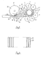
- the retractor 1 shown in Figure 1 consists essentially of an inner tube 2 and a plurality of rollers 3 which surround the tube 2 at a short distance.
- the rollers 3 are fastened to a plurality of drive axles 4 to 11 (FIG. 2) which are driven via associated gear wheels 12.
- the gear wheels 12 engage in a pinion 13 which is firmly connected to a further gear wheel 14.
- the gear 14 is driven by a toothed belt, not shown here.
- rollers 3 are arranged on each of their drive axles 4 to 11 with a small distance from one another, so that gaps arise between the rollers located on a drive axle.
- the rollers attached to an adjacent drive axle each engage in these gaps.
- the tube 2 is so closely surrounded by rollers 3 so that a poster inserted between rollers 3 and tube 2 cannot escape to the outside between the rollers.
- the tube 2 is firmly connected at one end 15 to the folding machine. In the illustrated embodiment, this connection is made via two supports 16 which are screwed to the frame 17 of the folding machine. The supports 16 completely surround the tube 2. The other end 18 of the tube 2 is self-supporting. As a result, a poster 19 (FIG. 2) wound up on the rollers 3 on the self-supporting end 18 can be pulled off the tube 2.
- a take-off device 20 which essentially consists of a transport roller 21 and a pressure roller 22.
- a poster wrapped between the transport roller 21 and the pressure roller 22 around the tube 2 is then pulled off the tube 2 in that the pressure roller 22 is pressed in the direction of the transport roller 21 through a slot 23 provided in the tube 2.
- the pressure roller 22 is actuated via a linkage 24 which is led out of the tube 2 at the other end 15. If the linkage 24 is pressed against a spring 25 in the direction of arrow a, the pressure roller 22 assumes the position shown here. The pressure roller 22 has this position during the reeling process.
- the linkage can be moved against the arrow direction a by the spring 25, whereby the pressure roller 22 is pressed through the slot 23 in the direction of the transport roller 21. Since the transport roller 21 rotates continuously in the specified direction, the poster roller located between the transport roller 21 and the pressure roller 22 is pulled off the tube 2 in the direction of the arrow b in this way.
- the poster roll then passes between two superposed conveyor belts 26, 27 which are part of a folding device which is described in more detail with reference to FIG. 4.
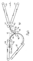
- FIG. 2 shows a simplified illustration of the side view of the retractor 1.
- the rollers 3 are arranged on several adjacent drive axes 4 to 11.
- the tube 2 is completely surrounded by the rollers 3, except for a narrow area, which can be referred to as the input area 28.
- the posters 19 are inserted between tube 2 and rollers 3.
- the Plalat 19 winds up to form a poster roller 29.
- the posters 19 are each passed over a deflection roller 31 under the roller 30.
- the roller 30 rotates continuously in the specified direction.
- Height-adjustable counter-pressure rollers 32 are arranged under the roller 30, which in their upper position press the poster 19 against the roller 30, so that the poster 19 is moved in the indicated direction c.
- the counter pressure rollers 32 are distributed over the length of the roller 30.
- the folding machine according to the invention has a guide device 33 so that a perfect paper feed is ensured.
- This essentially consists of guide rods 34 which engage in the recesses 35 provided on the roller 30.
- the design of the roller 30 with its recesses 35 is illustrated in FIG. 3.
- the guide rods 34 are designed such that their lower edge 36 is not arranged lower than the lowest point of the roller 30. In order that the engagement of a guide rod 34 in the associated recess 35 is clear, the roller 30 in FIG. 2 is at the corresponding point shown broken up.
- a rocker arm 37 which presses the poster roller 29 in the direction of the tube 2 on one side.
- the rocker arm 37 is rotatably mounted on an axis 38 attached outside its center of gravity, so that it presses against the poster roller 29 due to its own weight and the resulting torque.
- a lever not shown here, the rocker arm 37 can be brought into a position in which it no longer influences the diameter of the poster roller 29.
- the paper feed is preferably controlled via light barriers and stops, not shown here.
- a light barrier can be arranged in the specified area d, which detects the presence of a poster 19.
- a second light barrier can be provided in the area of the tube 2, which determines whether a poster roll 29 is in the reeling device.
- the paper feed can now be controlled via a control so that paper feed into the reel-up device is prevented when a poster is already in the reel-up device.
- the end of the reeling process can be controlled by means of a photo cell arranged in area d.
- the photocell recognizes the end of the poster of the poster pushed into the reel-up device and, after an adjustable time delay, causes the reel-up process to stop. This measure ensures that the poster end of the fully rolled up poster roll 29 is always in the same place at the end of the rolling up process.
- rollers 3 In order to enable the rollers 3 to be braked as suddenly as possible, it is advantageous if they consist of a material with the lowest possible mass. For this reason, the rollers 3 are preferably made of plastic.
- the sudden braking of the rollers 3 is obtained in that the drive shaft acting on the toothed belt is first uncoupled from the drive motor and braked immediately thereafter.
- the folding device 40 is shown.
- the poster roller 29 is pressed flat together by means of two conveyor belts 26, 27 tapering at an acute angle and passed under pressure between two pressure rollers 41, 42.
- the high pressure that the two pressure rollers 41, 42 exert on the pre-folded poster creates sharp-edged folds.
- a movable folding knife 43 is arranged behind the pressure rollers 41, 42. This folding knife 43 serves to fold the narrowly folded posters again in the middle. This center folding is necessary for posters with a large width.
- the poster passed between the pressure rollers 41 and 42 is passed under the vertical folding knife 43 until the Half of the poster has passed the folding knife in the dashed position. While the poster is being transported continuously, the folding knife 43 moves downward in accordance with the direction of the arrow indicated. As a result, the poster is pressed into the V-shaped funnel 44 and passed between two folding rollers 45. The folding knife 43 moves with the speed like the center of the poster.
- the bar 46, on which the folding knife 43 is fastened on the outside, moves in the direction indicated by the arrow at a decreasing angular velocity. The required decreasing angular velocity is achieved by a control cam, not shown here.
- the poster After the poster has passed through the folding rollers 45, it arrives at the exit of the folding device 40 via a third conveyor belt 47.
- Two further conveyor belts 48, 49 are also provided, between which posters of smaller dimensions are transported to the exit, since these smaller posters are in the middle do not need to be folded.
Landscapes
- Engineering & Computer Science (AREA)
- Mechanical Engineering (AREA)
- Folding Of Thin Sheet-Like Materials, Special Discharging Devices, And Others (AREA)
- Shaping Of Tube Ends By Bending Or Straightening (AREA)
Description
Die Erfindung betrifft eine Faltmaschine gemäss Oberbegriff des Hauptanspruchs.The invention relates to a folding machine according to the preamble of the main claim.
Plakate, wie sie an Plakatsäulen und Plakatwänden angeklebt werden, haben häufig grosse Abmessungen, weshalb sie vor dem Ankleben auf ein kleines Mass zusammengefaltet werden. Durch das Zusammenfalten wird das Ankleben der Plakate erheblich erleichtert. Dabei besteht die Forderung, die Plakate auf ein einheitliches Mass - beispielsweise auf eine Breite von 14 cm - zusammenzufalten. Um dies zu erreichen, müssen die Plakate, die Längen von 2 bis 3 m haben können, mehrfach gefaltet werden.Posters, such as those stuck to poster pillars and billboards, often have large dimensions, which is why they are folded to a small size before being glued on. Folding the posters will make it much easier to stick them on. There is a requirement to fold the posters to a uniform size - for example, to a width of 14 cm. To achieve this, the posters, which can have lengths of 2 to 3 m, have to be folded several times.
Aus der EP-A-0 007 442 ist eine Maschine zum Aufrollen und Falten von flexiblem Plastikmaterial bekannt. Bei dieser bekannten Faltmaschine ist eine zweiteilige Aufrollvorrichtung erforderlich, damit zwischen den beiden Teilen eine Falteinrichtung angreifen kann. Dies hat insbesondere den Nachteil, dass in dem mittleren, freien Bereich keine äussere Führung für das aufzurollende Material vorhanden ist. Aus diesem Grunde kann diese Faltmaschine nur mit verhältnismässig niedrigen Drehzahlen betrieben werden, damit das aufgerollte Material im freien Bereich durch die Zentrifugalkraft nicht deformiert und beschädigt wird.From EP-A-0 007 442 a machine for rolling up and folding flexible plastic material is known. In this known folding machine, a two-part retractor is required so that a folding device can engage between the two parts. This has the particular disadvantage that there is no external guide for the material to be rolled up in the central, free area. For this reason, this folding machine can only be operated at relatively low speeds, so that the rolled-up material is not deformed and damaged by the centrifugal force in the free area.
Auch die US-A-3 671 033 beschreibt eine Faltmaschine für Plastiktüten, die zwei im Abstand angeordnete Aufrollvorrichtungen besitzt, zwischen denen die Entnahme- und Faltstation angeordnet ist. Auch hier treten die gleichen Nachteile auf, weshalb diese Maschine für ein schnelles Aufrollen und Falten von Plakaten nicht geeignet ist.US-A-3 671 033 also describes a folding machine for plastic bags which has two roll-up devices which are arranged at a distance and between which the removal and folding station is arranged. The same disadvantages also occur here, which is why this machine is not suitable for quickly rolling up and folding posters.
Der Erfindung liegt die Aufgabe zugrunde, eine Faltmaschine zum Falten von Plakaten anzugeben, die mit hoher Arbeitsgeschwindigkeit eine Vielzahl von Faltungen ermöglicht.The invention has for its object to provide a folding machine for folding posters that enables a large number of folds at high working speed.
Die Lösung dieser Aufgabe wird mit den in Anspruch 1 angegebenen Merkmalen erreicht. In der Faltmaschine werden die zu faltenden Plakate von den mit einem gewissen Abstand vom Rohr angeordneten Rollen mit einer Plakatrolle aufgewikkelt. Zu diesem Zweck werden die Plakate an einem schmalen, nicht von Rollen überdeckten Bereich zwischen Rollen und Rohr eingeschoben. Die in Rotation versetzten Rollen führen dann das eingeführte Plakat um das Rohr herum, wobei der Abstand zwischen Rohr und äusseren Rollen sehr klein sein kann, beispielsweise 1 cm. Damit die aufgerollte Plakatrolle von dem inneren Rohr auf einfache Weise abgezogen werden kann, ist am freien Ende des Rohres eine Abzugsvorrichtung angeordnet, die die Plakatrolle vom Rohr axial abzieht und einer Falteinrichtung zuführt.This object is achieved with the features specified in
Die Abzugsvorrichtung besitzt im wesentlichen eine im Rohr angeordnete Andruckrolle und eine ausserhalb des Rohres befindliche Transportrolle, wobei die Andruckrolle durch einen Schlitz im Rohr in Richtung Transportrolle gedrückt werden kann. Dabei wird die dazwischenliegende Plakatrolle nach aussen abgezogen.The take-off device essentially has a pressure roller arranged in the tube and a transport roller located outside the tube, wherein the pressure roller can be pressed in the direction of the transport roller through a slot in the tube. The poster roll in between is pulled outwards.
Die erfindungsgemässe Faltmaschine ist bevorzugt so ausgebildet, dass in Verlängerung des freien Endes des Rohres eine Falteinrichtung angeordnet ist, die zwei in spitzem Winkel zusammenlaufende Transportbänder hat, die die jeweils abgezogene Plakatrolle flach zusammendrückt, und dass sich hinter den Transportbändern Druckrollen anschliessen, die ein durchlaufendes, zusammengedrücktes Plakat fest zusammenpressen. Der gesamte Faltvorgang läuft somit automatisch ab, wobei die Druckrollen gewährleisten, dass scharfkantige Falze entstehen.The folding machine according to the invention is preferably designed such that a folding device is arranged in the extension of the free end of the tube, which has two conveyor belts converging at an acute angle, which compresses the respective removed poster roll flat, and that pressure rollers are connected behind the conveyor belts, which are continuous , press the compressed poster firmly together. The entire folding process runs automatically, with the pressure rollers ensuring that sharp-edged folds are created.
Um eine mehrfache Faltung in Längsrichtung zu ermöglichen, kann zusätzlich ein Faltmesser vorgesehen sein, welches sich auf einer Kreisbahn von einer oberen, über dem gefalteten Plakat befindlichen Lage in eine waagrechte Stellung bewegt und dabei die jeweils von den Druckrollen kommenden Plakate in ihrer Mitte ergreift und durch einen V-förmigen Trichter drückt. Dabei entsteht ein zusätzlicher Mittenfalz der senkrecht zu den durch die Druckrollen erzeugten Falzen verläuft.In order to enable multiple folding in the longitudinal direction, a folding knife can also be provided, which moves on a circular path from an upper position above the folded poster to a horizontal position and thereby grabs the posters coming from the printing rollers in the middle and through a V-shaped funnel. This creates an additional center fold that is perpendicular to the folds created by the pressure rollers.
Vorteilhafte Weiterbildungen der Erfindung sind in den Unteransprüchen gekennzeichnet.Advantageous developments of the invention are characterized in the subclaims.
Die Erfindung wird nachfolgend anhand der Zeichnungen näher erläutert. Es zeigen:
Figur 1 die Aufrollvorrichtung einer erfindungsgemässen Faltmaschine,- Figur 2 die Seitenansicht der Aufrollvorrichtung mit der eingangsseitigen Walze,
- Figur 3 eine Ausführungsform der Walze und
- Figur 4 die der Aufrollvorrichtung nachgeschaltete Falteinrichtung.
- 1 shows the retractor of a folding machine according to the invention,
- FIG. 2 shows the side view of the reeling device with the roller on the input side,
- Figure 3 shows an embodiment of the roller and
- Figure 4 shows the folding device downstream of the retractor.
Die in Figur 1 dargestellte Aufrollvorrichtung 1 besteht im wesentlichen aus einem inneren Rohr 2 und mehreren Rollen 3, die das Rohr 2 mit geringem Abstand umgeben.The
Die Rollen 3 sind auf mehreren Antriebsachsen 4 bis 11 (Fig. 2) befestigt, die über zugeordnete Zahnräder 12 angetrieben werden. Die Zahnräder 12 greifen in ein Ritzel 13 ein, welches mit einem weiteren Zahnrad 14 fest verbunden ist. Das Zahnrad 14 wird von einem hier nicht dargestellten Zahnriemen angetrieben.The rollers 3 are fastened to a plurality of drive axles 4 to 11 (FIG. 2) which are driven via associated
Die Rollen 3sind auf jeder ihrer Antriebsachsen 4 bis 11 mit einem geringen Abstand voneinander angeordnet, so dass zwischen den auf einer Antriebsachse befindlichen Rollen Lücken entstehen. Die auf einer benachbarten Antriebsachse befestigten Rollen greifen jeweils in diese Lücken ein. Das Rohr 2 wird auf diese Weise so dicht von Rollen 3 umgeben, damit ein zwischen Rollen 3 und Rohr 2 eingelegtes Plakat nicht zwischen den Rollen nach aussen entweichen kann.The rollers 3 are arranged on each of their drive axles 4 to 11 with a small distance from one another, so that gaps arise between the rollers located on a drive axle. The rollers attached to an adjacent drive axle each engage in these gaps. The tube 2 is so closely surrounded by rollers 3 so that a poster inserted between rollers 3 and tube 2 cannot escape to the outside between the rollers.
Das Rohr 2 ist an seinem einen Ende 15 fest mit der Faltmaschine verbunden. Im dargestellten Ausführungsbeispiel erfolgt diese Verbindung über zwei Stützen 16, die mit dem Rahmen 17 der Faltmaschine verschraubt sind. Die Stützen 16 umschliessen das Rohr 2 vollständig. Das andere Ende 18 des Rohres 2 ist freitragend ausgebildet. Dadurch kann ein innen an den Rollen 3 aufgewikkeltes Plakat 19 (Fig. 2) am freitragenden Ende 18 vom Rohr 2 abgezogen werden.The tube 2 is firmly connected at one
Zu diesem Zweck ist eine Abzugsvorrichtung 20 vorgesehen, die im wesentlichen aus einer Transportrolle 21 und einer Andruckrolle 22 besteht. Ein zwischen Transportrolle 21 und Andruckrolle 22 um das Rohr 2 gewickeltes Plakat wird nun dadurch von dem Rohr 2 abgezogen, dass die Andruckrolle 22 durch einen im Rohr 2 vorgesehenen Schlitz 23 in Richtung Transportrolle 21 gedrückt wird. Die Betätigung der Andruckrolle 22 erfolgt dabei über ein Gestänge 24, welches am anderen Ende 15 aus dem Rohr 2 herausgeführt ist. Wird das Gestänge 24 gegen eine Feder 25 in Pfeilrichtung a gedrückt, so nimmt die Andruckrolle 22 die hier dargestellte Stellung ein. Die Andruckrolle 22 hat diese Stellung während des Aufrollvorganges inne. Ist der Aufrollvorgang beendet, so kann das Gestänge entgegen der Pfeilrichtung a durch die Feder25 bewegt werden, wodurch die Andruckrolle 22 durch den Schlitz 23 in Richtung Transportrolle 21 gedrückt wird. Da die Transportrolle 21 ständig in der angegebenen Richtung rotiert, wird die zwischen Transportrolle 21 und Andruckrolle 22 befindliche Plakatrolle auf diese Weise vom Rohr 2 in Pfeilrichtung b abgezogen.For this purpose, a take-off
Die Plakatrolle gelangt dann zwischen zwei übereinander angeordnete Transportbänder 26, 27, die Teil einer Falteinrichtung sind, welche anhand von Fig. 4 näher beschrieben wird.The poster roll then passes between two
Fig. 2 zeigt in vereinfachter Darstellung die Seitenansicht der Aufrollvorrichtung 1.2 shows a simplified illustration of the side view of the
Die Rollen 3 sind auf mehreren benachbarten Antriebsachsen 4 bis 11 angeordnet. Das Rohr 2 wird von den Rollen 3 vollständig umgeben, ausgenommen ein schmaler Bereich, der als Eingabebereich 28 bezeichnet werden kann. In diesem Eingabebereich 28 werden die Plakate 19 zwischen Rohr 2 und Rollen 3 eingeführt. Durch die Rotation der Rollen 3 in der angegebenen Richtung, wickelt sich das Plalat 19 zu einer Plakatrolle 29 auf.The rollers 3 are arranged on several adjacent drive axes 4 to 11. The tube 2 is completely surrounded by the rollers 3, except for a narrow area, which can be referred to as the
Bevor das Plakat 19 aufgerollt wird, wird es mittels einer Walze 30 geglättet. Zu diesem Zweck werden die Plakate 19 jeweils über eine Umlenkrolle 31 unter der Walze 30 hindurchgeführt. Die Walze 30 rotiert dabei ständig in der angegebenen Richtung. Unter der Walze 30 sind in der Höhe verstellbare Gegendruckrollen 32 angeordnet, die in ihrer oberen Stellung das Plakat 19 an die Walze 30 drücken, so dass das Plakat 19 in der angegebenen Richtung c bewegt wird. Die Gegendruckrollen 32 sind über die Länge der Walze 30 verteilt angeordnet.Before the poster 19 is rolled up, it is smoothed by means of a
Damit eine einwandfreie Papierzufuhr gewährleistet ist, hat die erfindungsgemässe Faltmaschine eine Führungseinrichtung 33. Diese besteht im wesentlichen aus Führungsstäben 34, die in an der Walze 30 vorgesehene Einstiche 35 eingreifen. Die Ausführung der Walze 30 mit ihren Einstichen 35 ist in Fig. 3 verdeutlicht.The folding machine according to the invention has a
Die Führungsstäbe 34 sind so ausgebildet, dass ihre Unterkante 36 nicht niedriger angeordnet ist, als der unterste Punkt der Walze 30. Damit der Eingriff eines Führungsstabes 34 in den zugehörigen Einstich 35 deutlich wird, ist die Walze 30 in Fig. 2 an der entsprechenden Stelle aufgebrochen dargestellt.The
Um einen störungsfreien Aufrollvorgang auch für Plakate grösserer Abmessungen zu gewährleisten, ist erfindungsgemäss ein Kipphebel 37 vorgesehen, der die Plakatrolle 29 einseitig in Richtung Rohr 2 eindrückt. Der Kipphebel 37 ist auf einer ausserhalb seines Schwerpunktes angebrachten Achse 38 drehbar gelagert, so dass er durch sein Eigengewicht und das daraus resultierende Drehmoment gegen die Plakatrolle 29 drückt. Mittels eines hier nicht dargestellten Hebels kann der Kipphebel 37 in eine Stellung gebracht werden, in der er den Durchmesser der Plakatrolle 29 nicht mehr beeinflusst.In order to ensure a trouble-free roll-up process even for posters of larger dimensions, a
Die Papierzufuhr wird vorzugsweise über hier nicht dargestellte Lichtschranken und Anschläge gesteuert. So kann beispielsweise in dem angegebenen Bereich d eine Lichtschranke angeordnet sein, die das Vorhandensein eines Plakates 19 erkennt. Gleichermassen kann eine zweite Lichtschranke im Bereich des Rohres 2 vorgesehen sein, die feststellt, ob eine Plakatrolle 29 in der Aufrollvorrichtung ist. Über eine Steuerung lässt sich nun die Papierzufuhr so steuern, dass eine Papierzufuhr in die Aufrollvorrichtung verhindert wird, wenn sich bereits ein Plakat in der Aufrollvorrichtung befindet.The paper feed is preferably controlled via light barriers and stops, not shown here. For example, a light barrier can be arranged in the specified area d, which detects the presence of a poster 19. Likewise, a second light barrier can be provided in the area of the tube 2, which determines whether a poster roll 29 is in the reeling device. The paper feed can now be controlled via a control so that paper feed into the reel-up device is prevented when a poster is already in the reel-up device.
Das Ende des Aufrollvorganges lässt sich mittels einer im Bereich d angeordneten Fotozelle steuern. Die Fotozelle erkennt das Plakatende des in die Aufrollvorrichtung eingeschobenen Plakates und veranlasst nach einer einstellbaren Zeitverzögerung das Abbrechen des Aufrollvorganges. Durch diese Massnahme ist gewährleistet, dass sich das Plakatende der vollständig aufgerollten Plakatrolle 29 bei Beendigung des Aufrollvorganges stets an derselben Stelle befindet.The end of the reeling process can be controlled by means of a photo cell arranged in area d. The photocell recognizes the end of the poster of the poster pushed into the reel-up device and, after an adjustable time delay, causes the reel-up process to stop. This measure ensures that the poster end of the fully rolled up poster roll 29 is always in the same place at the end of the rolling up process.
Um ein möglichst plötzliches Abbremsen der Rollen 3 zu ermöglichen, ist es günstig, wenn diese aus einem Material mit möglichst geringer Masse bestehen. Aus diesem Grunde bestehen die Rollen 3 bevorzugt aus Kunststoff.In order to enable the rollers 3 to be braked as suddenly as possible, it is advantageous if they consist of a material with the lowest possible mass. For this reason, the rollers 3 are preferably made of plastic.
Das plötzliche Abbremsen der Rollen 3 wird dadurch erhalten, dass die auf den Zahnriemen wirkende Antriebswelle zunächst vom Antriebsmotor entkuppelt und unmittelbar danach abgebremst wird.The sudden braking of the rollers 3 is obtained in that the drive shaft acting on the toothed belt is first uncoupled from the drive motor and braked immediately thereafter.
In Fig. 4 ist die Falteinrichtung 40 dargestellt.4, the
Über zwei in spitzem Winkel zulaufende Transportbänder 26, 27 wird die Plakatrolle 29 flach zusammengedrückt und unter Druck zwischen zwei Druckrollen 41, 42 hindurchgeführt. Durch den hohen Druck, den die beiden Druckrollen 41, 42 auf das vorgefaltete Plakat ausüben, entstehen scharfkantige Falze.The poster roller 29 is pressed flat together by means of two
Hinter den Druckrollen 41, 42 ist ein bewegliches Faltmesser 43 angeordnet. Dieses Faltmesser 43 dient dazu, die schmal zusammengefalteten Plakate nochmals in der Mitte zu falten. Diese Mittenfaltung ist bei Plakaten mit grosser Breite erforderlich.A
Das zwischen den Druckrollen 41 und 42 hindurchgeführte Plakat wird unter dem senkrecht stehenden Faltmesser43 hindurchgeführt, bis die Hälfte des Plakates das in der gestrichelten Stellung befindliche Faltmesser passiert hat. Während das Plakat kontinuierlich weitertransportiert wird, bewegt sich das Faltmesser 43 entsprechend der angegebenen Pfeilrichtung nach unten. Dadurch wird das Plakat in den V-förmigen Trichter 44 hineingedrückt und zwischen zwei Faltrollen 45 hindurchgeführt. Das Faltmesser 43 bewegt sich dabei mit der Geschwindigkeit wie die Mitte des Plakates. Der Balken 46, an dem das Faltmesser 43 aussen befestigt ist, bewegt sich dabei in der angegebenen Pfeilrichtung mit einer abnehmenden Winkelgeschwindigkeit. Die erforderliche abnehmende Winkelgeschwindigkeit wird durch einen hier nicht dargestellten Steuernocken erzielt.The poster passed between the
Nachdem das Plakat die Faltrollen 45 durchlaufen hat, gelangt es über ein drittes Transportband 47 zum Ausgang der Falteinrichtung 40. Es sind noch zwei weitere Transportbänder 48, 49 vorgesehen, zwischen denen Plakate kleinerer Abmessungen zum Ausgang transportiert werden, da diese kleineren Plakate in der Mitte nicht gefaltet werden müssen.After the poster has passed through the
Claims (5)
Priority Applications (3)
| Application Number | Priority Date | Filing Date | Title |
|---|---|---|---|
| EP81109910A EP0080519B1 (en) | 1981-11-26 | 1981-11-26 | Method and machine for folding posters |
| DE8181109910T DE3175074D1 (en) | 1981-11-26 | 1981-11-26 | Method and machine for folding posters |
| ES517180A ES517180A0 (en) | 1981-11-26 | 1982-11-06 | MACHINE FOR THE FOLDING OF POSTERS. |
Applications Claiming Priority (1)
| Application Number | Priority Date | Filing Date | Title |
|---|---|---|---|
| EP81109910A EP0080519B1 (en) | 1981-11-26 | 1981-11-26 | Method and machine for folding posters |
Publications (2)
| Publication Number | Publication Date |
|---|---|
| EP0080519A1 EP0080519A1 (en) | 1983-06-08 |
| EP0080519B1 true EP0080519B1 (en) | 1986-08-06 |
Family
ID=8188036
Family Applications (1)
| Application Number | Title | Priority Date | Filing Date |
|---|---|---|---|
| EP81109910A Expired EP0080519B1 (en) | 1981-11-26 | 1981-11-26 | Method and machine for folding posters |
Country Status (3)
| Country | Link |
|---|---|
| EP (1) | EP0080519B1 (en) |
| DE (1) | DE3175074D1 (en) |
| ES (1) | ES517180A0 (en) |
Families Citing this family (3)
| Publication number | Priority date | Publication date | Assignee | Title |
|---|---|---|---|---|
| US4479640A (en) * | 1983-07-22 | 1984-10-30 | Smith Carol E | Flat piece folding apparatus with variable speed, and method |
| DE3835023A1 (en) * | 1988-10-14 | 1990-04-19 | Gerhard Steidle | REWINDING DEVICE FOR PAPER, TEXTILE OR PLASTIC FILMS |
| DE19629606C2 (en) * | 1996-07-23 | 2001-05-10 | Fillmatic Polsterindustriemasc | Device for packaging mattresses surrounded by a fabric cover |
Family Cites Families (8)
| Publication number | Priority date | Publication date | Assignee | Title |
|---|---|---|---|---|
| DE276592C (en) * | 1911-03-20 | |||
| GB862296A (en) * | 1958-04-02 | 1961-03-08 | Strachan & Henshaw Ltd | Improvements in or relating to apparatus for folding paper or like webs |
| DE1295304B (en) * | 1963-07-29 | 1969-05-14 | Lee Kennth Philip | Roll-up device for winding web material without a winding carrier |
| ES360183A1 (en) * | 1968-11-02 | 1970-06-16 | Sala Granell | Machine for folding garment garments. (Machine-translation by Google Translate, not legally binding) |
| US3711085A (en) * | 1970-08-28 | 1973-01-16 | E Bunch | Folder for business forms |
| US3671033A (en) * | 1970-11-23 | 1972-06-20 | Coast Machinery Inc | Machine and method for folding plastic bags and the like |
| FR2412485A2 (en) * | 1977-12-26 | 1979-07-20 | Duflot Rene | Cloth folding machine - has support delivering cloths and belt discharging them travelling in same direction |
| US4180256A (en) * | 1978-06-28 | 1979-12-25 | Union Carbide Corporation | High speed bag folding machine |
-
1981
- 1981-11-26 DE DE8181109910T patent/DE3175074D1/en not_active Expired
- 1981-11-26 EP EP81109910A patent/EP0080519B1/en not_active Expired
-
1982
- 1982-11-06 ES ES517180A patent/ES517180A0/en active Granted
Also Published As
| Publication number | Publication date |
|---|---|
| ES8400349A1 (en) | 1983-11-01 |
| ES517180A0 (en) | 1983-11-01 |
| EP0080519A1 (en) | 1983-06-08 |
| DE3175074D1 (en) | 1986-09-11 |
Similar Documents
| Publication | Publication Date | Title |
|---|---|---|
| DE69421528T2 (en) | Rewinder with contact drive and method for minimizing the slip between drive roller and web | |
| EP3642144B1 (en) | Apparatus for supplying a coil-like padding product for packaging purposes | |
| EP0765809B1 (en) | Method for packaging a roll of web material | |
| DE69702583T2 (en) | Packaging machine | |
| DE2600522C2 (en) | ||
| DE3315495C2 (en) | Device for storing paper sheets or the like. | |
| DE2813100A1 (en) | DEVICE FOR LINING ELECTRICAL COMPONENTS WITH TWO ALIGNMENT WIRES TO A STRAP | |
| EP0968919A1 (en) | Method and device for enveloping quadrangular objects with a tape-like enveloping material | |
| EP0568844B1 (en) | Device and method for rolling a printing product and for enveloping the roll with an envelope | |
| DE2451993B2 (en) | Labeling station | |
| EP0958734B1 (en) | Round bale press for agricultural products | |
| EP3440946A1 (en) | Machine for the tobacco processing industry for simultaneously producing a number of strands | |
| EP0080519B1 (en) | Method and machine for folding posters | |
| DE19612924A1 (en) | Device for automatically feeding one end of a web of material | |
| DE4425662C1 (en) | Device for cross cutting a paper web | |
| DE4016484A1 (en) | Packing device for rolls of paper webs - has chain conveyor with stepped action and associated positioning and folding devices | |
| DE2446364A1 (en) | DEVICE FOR TRANSPORTING SHEETS, IN PARTICULAR ON CORRUGATED CARDBOARD MACHINES | |
| DE2944089C2 (en) | Guide device for a wrapping paper strip in a coin wrapping machine | |
| EP0481398B1 (en) | Wrapping device for bales in a baler press | |
| DE19652448C9 (en) | Device for packaging a roll of material web with a packaging web | |
| EP0221524B1 (en) | Arrangement for drawing webs | |
| EP0141394B1 (en) | Winding device for printed products arriving in a shingled formation | |
| DE3823705A1 (en) | DEVICE FOR SEPARATING CUTS FROM A STACK | |
| DE2139499C3 (en) | Device for wrapping cylindrical objects, in particular stacks of coins | |
| DE4004655A1 (en) | Winder machine for extensible sheeting - has winder sleeves, contact roller pivoting on pivot axle, and drive mechanism |
Legal Events
| Date | Code | Title | Description |
|---|---|---|---|
| PUAI | Public reference made under article 153(3) epc to a published international application that has entered the european phase |
Free format text: ORIGINAL CODE: 0009012 |
|
| 17P | Request for examination filed |
Effective date: 19820929 |
|
| AK | Designated contracting states |
Designated state(s): BE DE FR GB IT LU |
|
| GRAA | (expected) grant |
Free format text: ORIGINAL CODE: 0009210 |
|
| AK | Designated contracting states |
Kind code of ref document: B1 Designated state(s): BE DE FR GB IT LU |
|
| PG25 | Lapsed in a contracting state [announced via postgrant information from national office to epo] |
Ref country code: IT Free format text: LAPSE BECAUSE OF FAILURE TO SUBMIT A TRANSLATION OF THE DESCRIPTION OR TO PAY THE FEE WITHIN THE PRESCRIBED TIME-LIMIT;WARNING: LAPSES OF ITALIAN PATENTS WITH EFFECTIVE DATE BEFORE 2007 MAY HAVE OCCURRED AT ANY TIME BEFORE 2007. THE CORRECT EFFECTIVE DATE MAY BE DIFFERENT FROM THE ONE RECORDED. Effective date: 19860806 Ref country code: FR Free format text: THE PATENT HAS BEEN ANNULLED BY A DECISION OF A NATIONAL AUTHORITY Effective date: 19860806 Ref country code: BE Effective date: 19860806 |
|
| REF | Corresponds to: |
Ref document number: 3175074 Country of ref document: DE Date of ref document: 19860911 |
|
| PG25 | Lapsed in a contracting state [announced via postgrant information from national office to epo] |
Ref country code: LU Free format text: LAPSE BECAUSE OF NON-PAYMENT OF DUE FEES Effective date: 19861130 |
|
| EN | Fr: translation not filed | ||
| GBPC | Gb: european patent ceased through non-payment of renewal fee | ||
| PG25 | Lapsed in a contracting state [announced via postgrant information from national office to epo] |
Ref country code: DE Effective date: 19870801 |
|
| PG25 | Lapsed in a contracting state [announced via postgrant information from national office to epo] |
Ref country code: GB Effective date: 19881122 |
|
| PLBE | No opposition filed within time limit |
Free format text: ORIGINAL CODE: 0009261 |
|
| STAA | Information on the status of an ep patent application or granted ep patent |
Free format text: STATUS: NO OPPOSITION FILED WITHIN TIME LIMIT |
|
| 26N | No opposition filed |