EP0080389B1 - Contact électrique et application à un connecteur - Google Patents
Contact électrique et application à un connecteur Download PDFInfo
- Publication number
- EP0080389B1 EP0080389B1 EP82401926A EP82401926A EP0080389B1 EP 0080389 B1 EP0080389 B1 EP 0080389B1 EP 82401926 A EP82401926 A EP 82401926A EP 82401926 A EP82401926 A EP 82401926A EP 0080389 B1 EP0080389 B1 EP 0080389B1
- Authority
- EP
- European Patent Office
- Prior art keywords
- fact
- connector
- axis
- electrical
- contact
- Prior art date
- Legal status (The legal status is an assumption and is not a legal conclusion. Google has not performed a legal analysis and makes no representation as to the accuracy of the status listed.)
- Expired
Links
- 239000004020 conductor Substances 0.000 claims description 34
- 239000007787 solid Substances 0.000 claims 2
- 230000008878 coupling Effects 0.000 description 11
- 238000010168 coupling process Methods 0.000 description 11
- 238000005859 coupling reaction Methods 0.000 description 11
- 238000000034 method Methods 0.000 description 3
- 230000010196 hermaphroditism Effects 0.000 description 2
- 239000011810 insulating material Substances 0.000 description 2
- 230000000295 complement effect Effects 0.000 description 1
- 230000005611 electricity Effects 0.000 description 1
- 239000002184 metal Substances 0.000 description 1
- 230000000149 penetrating effect Effects 0.000 description 1
Images

Classifications
-
- H—ELECTRICITY
- H01—ELECTRIC ELEMENTS
- H01R—ELECTRICALLY-CONDUCTIVE CONNECTIONS; STRUCTURAL ASSOCIATIONS OF A PLURALITY OF MUTUALLY-INSULATED ELECTRICAL CONNECTING ELEMENTS; COUPLING DEVICES; CURRENT COLLECTORS
- H01R13/00—Details of coupling devices of the kinds covered by groups H01R12/70 or H01R24/00 - H01R33/00
- H01R13/02—Contact members
-
- H—ELECTRICITY
- H01—ELECTRIC ELEMENTS
- H01R—ELECTRICALLY-CONDUCTIVE CONNECTIONS; STRUCTURAL ASSOCIATIONS OF A PLURALITY OF MUTUALLY-INSULATED ELECTRICAL CONNECTING ELEMENTS; COUPLING DEVICES; CURRENT COLLECTORS
- H01R12/00—Structural associations of a plurality of mutually-insulated electrical connecting elements, specially adapted for printed circuits, e.g. printed circuit boards [PCB], flat or ribbon cables, or like generally planar structures, e.g. terminal strips, terminal blocks; Coupling devices specially adapted for printed circuits, flat or ribbon cables, or like generally planar structures; Terminals specially adapted for contact with, or insertion into, printed circuits, flat or ribbon cables, or like generally planar structures
- H01R12/70—Coupling devices
- H01R12/77—Coupling devices for flexible printed circuits, flat or ribbon cables or like structures
-
- H—ELECTRICITY
- H01—ELECTRIC ELEMENTS
- H01R—ELECTRICALLY-CONDUCTIVE CONNECTIONS; STRUCTURAL ASSOCIATIONS OF A PLURALITY OF MUTUALLY-INSULATED ELECTRICAL CONNECTING ELEMENTS; COUPLING DEVICES; CURRENT COLLECTORS
- H01R4/00—Electrically-conductive connections between two or more conductive members in direct contact, i.e. touching one another; Means for effecting or maintaining such contact; Electrically-conductive connections having two or more spaced connecting locations for conductors and using contact members penetrating insulation
- H01R4/24—Connections using contact members penetrating or cutting insulation or cable strands
- H01R4/2416—Connections using contact members penetrating or cutting insulation or cable strands the contact members having insulation-cutting edges, e.g. of tuning fork type
- H01R4/242—Connections using contact members penetrating or cutting insulation or cable strands the contact members having insulation-cutting edges, e.g. of tuning fork type the contact members being plates having a single slot
Definitions
- the present invention relates to electrical contacts, as well as their applications in a connector.
- the current technique has developed a certain number of cables having particular structures and among these, we know the so-called flat laminated cables or flat cables.
- These cables made up of a plurality of electrical conductors, are commonly used in all industries, and are generally connected to connectors in order to be able to connect or disconnect these cables.
- this distance is not always the same for each cable; it can be less, equal or greater than the distances separating the electrical contacts in a connector.
- the electrical contacs are made so that the offset between the two ends follows a determined progression so that all the conductors are connected to the contact connector coupling.
- the present invention aims to overcome these drawbacks and to achieve in particular an electrical contact making it possible to obtain the offset between these two ends in a simple embodiment, easy to implement, and which, moreover, can allow '' obtain all the possible law of variation defining the distance separating these two ends.
- the subject of the present invention is an electrical contact characterized in that it comprises two connectable parts, said first part comprising a pin for connection to an electrical conductor, along a first axis, a lug integral with said pin having a fixing direction along a second axis, said first and second axes being substantially parallel and distant from each other, by a determined value, said second part comprising, a fixing head capable of cooperating with said first part in one plurality of positions with respect to a third median axis over two distances on either side of said median axis, these two distances respectively having values substantially equal to said determined value, and a longitudinal coupling endpiece integral with said head attachment, this longitudinal coupling end being defined on a fourth axis, said fourth axis being substantially coincident with said three th median axis.
- the present invention also relates to a connector comprising a plurality of electrical contacts defined above.
- the part 41 comprises a connection pin 2 with an electrical conductor on an axis 3 which is defined in this embodiment by a self-cutting or self-stripping slot 4 allowing, by penetrating the conductor through the opening 5, to cut out its insulating sheath, and to position it in the bottom of this slot 4 defined along the axis 3, so that the conductive core is in contact with this pin 2 which, of course, is made of a conductive material of the 'electricity.
- This part 41 further comprises a lug 6 integral with the spindle 2, this lug 6 is substantially constituted by an oblong part having an orientation axis 7 substantially parallel to the coupling axis of the spindle 2, but offset of it of a certain determined quantity which, for the understanding of the description, will have a value a.
- this unitary piece 41 can be produced by cutting from relatively flat sheet metal, having a thickness sufficient to nevertheless exhibit a certain rigidity.
- the contact also comprises, on the other hand, the part 42 which consists of a head 8 having at its end 9, a clamp 10 consisting of two edges 11 and 12 having an elasticity, for example obtained by prestressing, so that these edges 11 and 12 tend to approach each other.
- this clamp is integral with a rigid body 13 supporting the two elements of the clamp 10.
- the width of possibility of pinching of this clamp 10 is located in a direction perpendicular to a so-called median axis 14, so that the width of this clamp substantially perpendicular to this median axis 14 is equal to twice the determined value defined above, that is to say in fact equal to 2 a.
- this part 42 comprises, integral with the rigid body 13, an end piece 15 called a coupling which has the function of being able to cooperate with another end piece in the manner of an electrical connection, that is to say that this tip can have a male function or a female function, in particular in any type of connector, and in particular even, connectors of the hermaphrodite type.
- This tip generally being made of an oblong piece, is arranged so that its longitudinal axis is substantially coincident with the median axis 14 defined above.
- the two parts 41 and 42 can be connected as illustrated in this FIG. 1, that is to say that the part 41, by means of its tab 6, is introduced into the clamp 10 so that the two elastic edges 11 and 12 bear firmly on the side wall of the tab 6, and that, due to the respective length of these two edges 11 and 12, maintain this part 41 in a relatively rigid position relative to the part 42.
- the contact described with reference to FIG. 1 has advantages because, since the tab 6 has a relatively small width compared to the width of the clamp 10, and that the axis 14 is offset from the axis 3 , it presents a large number of positioning possibilities.
- connection between these two parts 41 and 42 are innumerable and make it possible to obtain a connection between a conductor which is offset on either side of the coupling end piece by an amount between 0 and 2 ⁇ .
- the pin 2 will also be offset with respect to the median axis 14, by an amount 2 a.
- the conductor arrives in position so that it is located opposite the median axis 14 and, therefore, by positioning the tab 6 on an extreme edge of the clamp 10, but in turning the spindle 2 in the space delimited by the two edges of this clamp 10, it can be seen that the offset between the axis 3 of the spindle 2 and the axis 14 of the tab 6 is substantially equal to a , the axis 3 of the spindle 2 will be substantially coincident with the median axis 14.
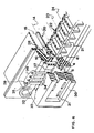
- Such an electrical contact is particularly advantageous in the case of a connector with several contacts, that is to say the connectors of the "strip" type, comprising a plurality of coupling contacts arranged one next to the other in a base made of an insulating material.
- Figure 6 partially shows such a connector in a partially cut away view.
- This connector therefore comprises a plurality of contacts 20 identical to that which has been described with reference to FIG. 1, these contacts 20, only one of which is shown in the figure for the purpose of simplification, are arranged in housings 21 produced in a base 22.
- the parts 41 will be arranged in the clamp 10 of the part 42 so that for each contact disposed one beside the other the distance separating the two connection slots 4 from these contacts is distant from Y.
- the base 22 has been shown so as to be made of an insulating material consisting of two parts 25 and 26 which fit into one another so as to maintain
- the conductors may also be held laterally between these two faces by bosses 34 made for example on the body 30 as shown in the figure.
Landscapes
- Multi-Conductor Connections (AREA)
- Coupling Device And Connection With Printed Circuit (AREA)
Applications Claiming Priority (2)
| Application Number | Priority Date | Filing Date | Title |
|---|---|---|---|
| FR8119899 | 1981-10-23 | ||
| FR8119899A FR2515435A1 (fr) | 1981-10-23 | 1981-10-23 | Contact electrique et application a un connecteur |
Publications (2)
| Publication Number | Publication Date |
|---|---|
| EP0080389A1 EP0080389A1 (fr) | 1983-06-01 |
| EP0080389B1 true EP0080389B1 (fr) | 1986-01-15 |
Family
ID=9263311
Family Applications (1)
| Application Number | Title | Priority Date | Filing Date |
|---|---|---|---|
| EP82401926A Expired EP0080389B1 (fr) | 1981-10-23 | 1982-10-20 | Contact électrique et application à un connecteur |
Country Status (5)
| Country | Link |
|---|---|
| US (1) | US4458970A (enExample) |
| EP (1) | EP0080389B1 (enExample) |
| JP (1) | JPS58135586A (enExample) |
| DE (1) | DE3268587D1 (enExample) |
| FR (1) | FR2515435A1 (enExample) |
Families Citing this family (10)
| Publication number | Priority date | Publication date | Assignee | Title |
|---|---|---|---|---|
| GB2171856A (en) * | 1985-02-15 | 1986-09-03 | Trw Connectors | Electrical connector component |
| US4824380A (en) * | 1987-11-24 | 1989-04-25 | Elcon Products International Company | Quick disconnect connector and system with integral conductor |
| GB9622955D0 (en) * | 1996-11-04 | 1997-01-08 | Amp Great Britain | Connector for flat flexible cable |
| US6116931A (en) * | 1997-11-10 | 2000-09-12 | The Whitaker Corporation | Contact array for electrical interface connector |
| USD409576S (en) * | 1998-04-12 | 1999-05-11 | Elcon Products International | Electrical connector housing |
| USD412489S (en) * | 1998-04-16 | 1999-08-03 | Elcon Products International | Electrical connector housing |
| USD408789S (en) | 1998-04-16 | 1999-04-27 | Elcon Products International Company | Electrical connector housing |
| US8591248B2 (en) | 2011-01-20 | 2013-11-26 | Tyco Electronics Corporation | Electrical connector with terminal array |
| US20130178080A1 (en) * | 2012-01-09 | 2013-07-11 | Kostal Of America, Inc. | Soldered electronic components mounted solely on the top surface of a printed circuit board |
| JP7558095B2 (ja) * | 2021-03-19 | 2024-09-30 | 日本航空電子工業株式会社 | コネクタおよび接続方法 |
Family Cites Families (10)
| Publication number | Priority date | Publication date | Assignee | Title |
|---|---|---|---|---|
| US1530011A (en) * | 1923-03-20 | 1925-03-17 | Pacent Electric Company Inc | Electrical connecting device |
| US3375481A (en) * | 1966-04-01 | 1968-03-26 | Bunker Ramo | Cable connector |
| FR2351514A1 (fr) * | 1976-05-13 | 1977-12-09 | Souriau & Cie | Perfectionnements apportes aux connecteurs pour cablages plats |
| US4140360A (en) * | 1977-10-13 | 1979-02-20 | Amp Incorporated | Connector for mass termination of flat multiple wire cable |
| US4190952A (en) * | 1978-06-27 | 1980-03-04 | Circuit Assembly Corp. | Insulation displacement connector adapter |
| US4418977A (en) * | 1978-10-16 | 1983-12-06 | Continental-Wirt Electronics Corporation | Connector structure for flat cable |
| US4266843A (en) * | 1979-09-24 | 1981-05-12 | The Bendix Corporation | Insulation displacing electrical contact and method of making same |
| US4470655A (en) * | 1979-11-01 | 1984-09-11 | Minnesota Mining And Manufacturing Company | Transition connector |
| US4417780A (en) * | 1980-04-30 | 1983-11-29 | Thomas & Betts Corporation | Pitch transition connector |
| US4351582A (en) * | 1980-05-23 | 1982-09-28 | Robinson Nugent, Inc. | Adapting electrical connector |
-
1981
- 1981-10-23 FR FR8119899A patent/FR2515435A1/fr active Granted
-
1982
- 1982-10-20 US US06/435,620 patent/US4458970A/en not_active Expired - Fee Related
- 1982-10-20 EP EP82401926A patent/EP0080389B1/fr not_active Expired
- 1982-10-20 DE DE8282401926T patent/DE3268587D1/de not_active Expired
- 1982-10-22 JP JP57184786A patent/JPS58135586A/ja active Pending
Also Published As
| Publication number | Publication date |
|---|---|
| US4458970A (en) | 1984-07-10 |
| DE3268587D1 (en) | 1986-02-27 |
| FR2515435A1 (fr) | 1983-04-29 |
| JPS58135586A (ja) | 1983-08-12 |
| EP0080389A1 (fr) | 1983-06-01 |
| FR2515435B1 (enExample) | 1984-11-16 |
Similar Documents
| Publication | Publication Date | Title |
|---|---|---|
| EP0674358B1 (fr) | Organe de contact électrique femelle | |
| EP0681345B1 (fr) | Organe de contact électrique hermaphrodite | |
| FR2711853A1 (fr) | Organe de contact électrique femelle. | |
| FR2732518A1 (fr) | Agencement de connexion pour fils conducteurs electriques et module, notamment de type bloc de jonction, equipe d'un tel agencement | |
| EP1916743B1 (fr) | Appareil électrique comprenant au moins une borne de raccordement à ressort | |
| EP0743702B1 (fr) | Dispositif à contacts électriques à déplacement d'isolant | |
| EP0080389B1 (fr) | Contact électrique et application à un connecteur | |
| EP0470887A1 (fr) | Connecteur de dérivation | |
| EP0723314B1 (fr) | Connecteur électrique | |
| EP3227966B1 (fr) | Element de connexion electrique a perçage de gaine isolante d'un fil electrique | |
| EP3790126B1 (fr) | Ensemble pour connecteurs adapté à un montage en aveugle | |
| FR2750261A1 (fr) | Structure de connexion pour un corps de circuit plat et un connecteur | |
| FR3125644A1 (fr) | Dispositif de connexion d’un terminal d’un module de batterie a un conducteur electrique | |
| FR2514956A1 (fr) | Dispositif de connexion a enfichage | |
| FR2772993A1 (fr) | Organe de contact electrique femelle | |
| EP0251909B1 (fr) | Elément de connexion pour câble électrique monoconducteur à connexion axiale | |
| EP0407249B1 (fr) | Organe de contact électrique femelle | |
| EP0926766A1 (fr) | Organe de contact électrique femelle | |
| EP0810687A1 (fr) | Connecteur électrique pour connecter des conducteurs électriques | |
| FR2783638A1 (fr) | Organe de contact electrique femelle | |
| FR2851083A1 (fr) | Connecteur electrique a organe de manoeuvre | |
| EP3336967A1 (fr) | Elément de connexion électrique | |
| FR2813997A1 (fr) | Dispositif de liaison d'un conducteur a une piste conductrice | |
| EP0470882A1 (fr) | Organe de contact électrique à déplacement d'isolant | |
| FR2743942A1 (fr) | Organe femelle de contact electrique |
Legal Events
| Date | Code | Title | Description |
|---|---|---|---|
| PUAI | Public reference made under article 153(3) epc to a published international application that has entered the european phase |
Free format text: ORIGINAL CODE: 0009012 |
|
| AK | Designated contracting states |
Designated state(s): DE GB IT NL |
|
| 17P | Request for examination filed |
Effective date: 19830920 |
|
| ITF | It: translation for a ep patent filed | ||
| GRAA | (expected) grant |
Free format text: ORIGINAL CODE: 0009210 |
|
| AK | Designated contracting states |
Designated state(s): DE GB IT NL |
|
| REF | Corresponds to: |
Ref document number: 3268587 Country of ref document: DE Date of ref document: 19860227 |
|
| R20 | Corrections of a patent specification |
Effective date: 19860407 |
|
| PLBE | No opposition filed within time limit |
Free format text: ORIGINAL CODE: 0009261 |
|
| STAA | Information on the status of an ep patent application or granted ep patent |
Free format text: STATUS: NO OPPOSITION FILED WITHIN TIME LIMIT |
|
| 26N | No opposition filed | ||
| ITTA | It: last paid annual fee | ||
| PGFP | Annual fee paid to national office [announced via postgrant information from national office to epo] |
Ref country code: GB Payment date: 19941019 Year of fee payment: 13 |
|
| PGFP | Annual fee paid to national office [announced via postgrant information from national office to epo] |
Ref country code: NL Payment date: 19941031 Year of fee payment: 13 |
|
| PGFP | Annual fee paid to national office [announced via postgrant information from national office to epo] |
Ref country code: DE Payment date: 19941122 Year of fee payment: 13 |
|
| PG25 | Lapsed in a contracting state [announced via postgrant information from national office to epo] |
Ref country code: GB Effective date: 19951020 |
|
| PG25 | Lapsed in a contracting state [announced via postgrant information from national office to epo] |
Ref country code: NL Effective date: 19960501 |
|
| GBPC | Gb: european patent ceased through non-payment of renewal fee |
Effective date: 19951020 |
|
| NLV4 | Nl: lapsed or anulled due to non-payment of the annual fee |
Effective date: 19960501 |
|
| PG25 | Lapsed in a contracting state [announced via postgrant information from national office to epo] |
Ref country code: DE Effective date: 19960801 |