EP0080261A2 - Liquid dispensing package and valve - Google Patents
Liquid dispensing package and valve Download PDFInfo
- Publication number
- EP0080261A2 EP0080261A2 EP82305383A EP82305383A EP0080261A2 EP 0080261 A2 EP0080261 A2 EP 0080261A2 EP 82305383 A EP82305383 A EP 82305383A EP 82305383 A EP82305383 A EP 82305383A EP 0080261 A2 EP0080261 A2 EP 0080261A2
- Authority
- EP
- European Patent Office
- Prior art keywords
- cap
- valve
- package
- container
- seal
- Prior art date
- Legal status (The legal status is an assumption and is not a legal conclusion. Google has not performed a legal analysis and makes no representation as to the accuracy of the status listed.)
- Withdrawn
Links
Images

Classifications
-
- B—PERFORMING OPERATIONS; TRANSPORTING
- B67—OPENING, CLOSING OR CLEANING BOTTLES, JARS OR SIMILAR CONTAINERS; LIQUID HANDLING
- B67D—DISPENSING, DELIVERING OR TRANSFERRING LIQUIDS, NOT OTHERWISE PROVIDED FOR
- B67D1/00—Apparatus or devices for dispensing beverages on draught
- B67D1/0042—Details of specific parts of the dispensers
- B67D1/0057—Carbonators
- B67D1/0069—Details
- B67D1/0071—Carbonating by injecting CO2 in the liquid
- B67D1/0072—Carbonating by injecting CO2 in the liquid through a diffuser, a bubbler
-
- B—PERFORMING OPERATIONS; TRANSPORTING
- B67—OPENING, CLOSING OR CLEANING BOTTLES, JARS OR SIMILAR CONTAINERS; LIQUID HANDLING
- B67D—DISPENSING, DELIVERING OR TRANSFERRING LIQUIDS, NOT OTHERWISE PROVIDED FOR
- B67D1/00—Apparatus or devices for dispensing beverages on draught
- B67D1/0042—Details of specific parts of the dispensers
- B67D1/0043—Mixing devices for liquids
- B67D1/0051—Mixing devices for liquids for mixing outside the nozzle
- B67D1/0052—Mixing devices for liquids for mixing outside the nozzle by means for directing respective streams together
-
- B—PERFORMING OPERATIONS; TRANSPORTING
- B67—OPENING, CLOSING OR CLEANING BOTTLES, JARS OR SIMILAR CONTAINERS; LIQUID HANDLING
- B67D—DISPENSING, DELIVERING OR TRANSFERRING LIQUIDS, NOT OTHERWISE PROVIDED FOR
- B67D1/00—Apparatus or devices for dispensing beverages on draught
- B67D1/0042—Details of specific parts of the dispensers
- B67D1/0057—Carbonators
- B67D1/0069—Details
- B67D1/007—Structure of the carbonating chamber
-
- B—PERFORMING OPERATIONS; TRANSPORTING
- B67—OPENING, CLOSING OR CLEANING BOTTLES, JARS OR SIMILAR CONTAINERS; LIQUID HANDLING
- B67D—DISPENSING, DELIVERING OR TRANSFERRING LIQUIDS, NOT OTHERWISE PROVIDED FOR
- B67D1/00—Apparatus or devices for dispensing beverages on draught
- B67D1/0042—Details of specific parts of the dispensers
- B67D1/0078—Ingredient cartridges
- B67D1/0079—Ingredient cartridges having their own dispensing means
-
- B—PERFORMING OPERATIONS; TRANSPORTING
- B67—OPENING, CLOSING OR CLEANING BOTTLES, JARS OR SIMILAR CONTAINERS; LIQUID HANDLING
- B67D—DISPENSING, DELIVERING OR TRANSFERRING LIQUIDS, NOT OTHERWISE PROVIDED FOR
- B67D1/00—Apparatus or devices for dispensing beverages on draught
- B67D1/04—Apparatus utilising compressed air or other gas acting directly or indirectly on beverages in storage containers
-
- B—PERFORMING OPERATIONS; TRANSPORTING
- B67—OPENING, CLOSING OR CLEANING BOTTLES, JARS OR SIMILAR CONTAINERS; LIQUID HANDLING
- B67D—DISPENSING, DELIVERING OR TRANSFERRING LIQUIDS, NOT OTHERWISE PROVIDED FOR
- B67D1/00—Apparatus or devices for dispensing beverages on draught
- B67D1/08—Details
- B67D1/12—Flow or pressure control devices or systems, e.g. valves, gas pressure control, level control in storage containers
- B67D1/14—Reducing valves or control taps
- B67D1/1405—Control taps
-
- B—PERFORMING OPERATIONS; TRANSPORTING
- B67—OPENING, CLOSING OR CLEANING BOTTLES, JARS OR SIMILAR CONTAINERS; LIQUID HANDLING
- B67D—DISPENSING, DELIVERING OR TRANSFERRING LIQUIDS, NOT OTHERWISE PROVIDED FOR
- B67D1/00—Apparatus or devices for dispensing beverages on draught
- B67D1/08—Details
- B67D1/0801—Details of beverage containers, e.g. casks, kegs
-
- B—PERFORMING OPERATIONS; TRANSPORTING
- B67—OPENING, CLOSING OR CLEANING BOTTLES, JARS OR SIMILAR CONTAINERS; LIQUID HANDLING
- B67D—DISPENSING, DELIVERING OR TRANSFERRING LIQUIDS, NOT OTHERWISE PROVIDED FOR
- B67D1/00—Apparatus or devices for dispensing beverages on draught
- B67D1/0042—Details of specific parts of the dispensers
- B67D1/0081—Dispensing valves
- B67D2001/0087—Dispensing valves being mounted on the dispenser housing
-
- B—PERFORMING OPERATIONS; TRANSPORTING
- B67—OPENING, CLOSING OR CLEANING BOTTLES, JARS OR SIMILAR CONTAINERS; LIQUID HANDLING
- B67D—DISPENSING, DELIVERING OR TRANSFERRING LIQUIDS, NOT OTHERWISE PROVIDED FOR
- B67D1/00—Apparatus or devices for dispensing beverages on draught
- B67D1/08—Details
- B67D1/0801—Details of beverage containers, e.g. casks, kegs
- B67D2001/0812—Bottles, cartridges or similar containers
- B67D2001/0814—Bottles, cartridges or similar containers for upside down use
- B67D2001/0815—Bottles, cartridges or similar containers for upside down use with integral venting tube
-
- B—PERFORMING OPERATIONS; TRANSPORTING
- B67—OPENING, CLOSING OR CLEANING BOTTLES, JARS OR SIMILAR CONTAINERS; LIQUID HANDLING
- B67D—DISPENSING, DELIVERING OR TRANSFERRING LIQUIDS, NOT OTHERWISE PROVIDED FOR
- B67D2210/00—Indexing scheme relating to aspects and details of apparatus or devices for dispensing beverages on draught or for controlling flow of liquids under gravity from storage containers for dispensing purposes
- B67D2210/00028—Constructional details
- B67D2210/00031—Housing
- B67D2210/00034—Modules
-
- B—PERFORMING OPERATIONS; TRANSPORTING
- B67—OPENING, CLOSING OR CLEANING BOTTLES, JARS OR SIMILAR CONTAINERS; LIQUID HANDLING
- B67D—DISPENSING, DELIVERING OR TRANSFERRING LIQUIDS, NOT OTHERWISE PROVIDED FOR
- B67D2210/00—Indexing scheme relating to aspects and details of apparatus or devices for dispensing beverages on draught or for controlling flow of liquids under gravity from storage containers for dispensing purposes
- B67D2210/00028—Constructional details
- B67D2210/00031—Housing
- B67D2210/00039—Panels
Landscapes
- Chemical & Material Sciences (AREA)
- Chemical Kinetics & Catalysis (AREA)
- Devices For Dispensing Beverages (AREA)
- Closures For Containers (AREA)
Abstract
The invention provides a package for holding concentrated syrup. The cap seals to the body, and by turning the cap concentrate can be dispensed from the package through an outlet in the cap. The package fits in a dispensing valve having a member displacement of which causes dispensing of the concentrate and at the same time supply of carbon dioxide gas to the interior of the package to drive the concentrate therefrom and cause a flow of carbonated water to mix with the dispensed concentrate to produce a carbonated drink. The invention concerns novel constructions of the package and dispensing valve.
Description
- This invention relates to a package which is for holding a quantity of liquid, and which is adapted so that, under certain circumstances, the liquid can be dispensed therefrom at will, and to a dispensing valve therefore.
- Although the package according to the invention can be used for the dispensing of any liquid which required to be dispensed, we are particularly interested in the utilization of the package for the dispensing of a concentrate for mixing with a diluent, e.g. for dispensing a flavouring syrup, in .order to produce a carbonated beverage. That is to say, the package is adapted for connection to a dispensing system, such as might be embodied in a dispensing machine. Such a dispensing machine would be provided with a means for dispensing a diluent such as hot, cold or carbonated water, and the arrangement would be that upon operation of an actuator, such as a button, lever or the like, the diluent and concentrate are dispensed in predetermined ratios, into a drinking or other vessel, to provide a beverage suitable for consumption. In such an arrangement, if desired, any suitable carbonating, refrigerating and/or heating system can be used, but as will become clear hereinafter, the package according to the present invention in addition to serving as the container for holding the quantity of concentrate also uniquely is provided with particular valving arrangements thereby in particular to facilitate the dispensing of concentrate in a system as outlined above.
- Typically in the prior art, dispensers for mixing a concentrate, such as a flavoured syrup, with a diluent, such as carbonated water, carry out their mixing in a mixing tap from which the mixed beverage is dispensed into a cup or glass. Typically, both the diluent and concentrate are conducted through tubing to a valving mechanism at the tap which meters the amounts of diluent and concentrate dispensed and mixed at the tap. Other units, which have been designed particularly for in-home use, separately dispense the concentrate and carbonated water. In such devices, the user must first dispense concentrate into his cup, usually simply by judgement without any metering provided, and then add to the dispensed concentrate an amount of carbonated water.
- In dispensing devices in which mixing is done at the tap, there are serious disadvantages. First of all, dilute concentrate, which is typically a syyrup, remains in the area of the tap. As a result, there is a likelihood of mold formation and, unless the apparatus is regularly used and regularly cleaned, unsanitary conditions result.
- Secondly, where it is desired to supply a number of different types of drinks, the valving arrangements to couple into the tap the different concentrates becomes complex. Because of the use of tubing in the system, or if one tap is used to dispense different flavours, when one switches concentrates, some of the previous concentrate may remain in the system and at least initially the desired drink will not be obtained. Devices which utilise separate concentrate and water dispensers suffer from other disadvantages, particularly the disadvantage that a consistent quality drink will not be obtained since it is generally a matter of judgement in what proportions to mix the concentrate and water. Furthermore poor mixing takes place without stirring in which case carbonation is lost.
- Thus, it is evident that previous dispensing arrangement have suffered from various disadvantages because of which the widespread use of carbonated beverage dispensers in the home has not come about.
- In view of these difficulties, there has been invented a package for holding a quantity of liquid, particularly a concentrate for mixing with a diluent to provide a beverage, in which metering of the concentrate takes place in the container thereby permitting the concentrate to be dispensed directly from the container into a drinking vessel with mixing taking place just prior to or at the entry into the drinking vessel, in such a manner that dilute concentrate will not be present in the dispensing apparatus and the changing of concentrates will be facilitated, and such invention is set forth in European Patent Application No. 80200611.4, published under No. 0022589. Such Application also discloses a word dispensing valve and machine for use with the package.
- It is an object of the present invention to provide improvements in the package and dispensing valve disclosed in said European Application, referred to herein as the Prior Application, especially but not exclusively to make the package and dispensing valve suitable for the dispensing of diet syrup.
- As the disclosure of the Prior Application is extensive and is relevant to the embodiment of the invention which follows, the entire disclosure of the said Prior Application is imported into this specification for the purposes of reference.
- The novel aspects of the present invention are explained with reference to embodiments of package and dispensing valve of the present invention, which embodiments are illustrated in and are now described with reference to the accompanying drawings, wherein:-
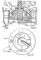
- Figure 1 is an exploded perspective view of a preferred embodiment of dispensing valve for use in the present invention;
- Figure 2 is a cross sectional view through the valve shown in Figure 1, with a package according to the invention fitted thereto; and
- Figure 3 is a bottom plan view of the arrangement of Figure 1.
- Figure 1 shows an improved form of valve and manifold according to the present invention. The arrangement is essentially the same as that shown in Figure 6 of the Prior Application. The embodiment of Figure 1, however, is adapted for easier molding and is also adapted to be used with an improved form of valving mechanism in the container. Manifold 77a contains appropriate bores 182a to receive the rotating valve members 189a. As in the embodiment of Figure 6 of the Prior Application, an outlet opening 105 for the diluent surrounded by an
O ring seal 109 and an outlet opening 119 for the carbon dioxide surrounded by an 0 ring seal 123 are provided. The passages leading to theoutlets passages 225a and 235a in the central rotating valve member 189a as will be seen below. A central opening 185a through which thespout 237a extends for dispensing diluent and also from which the concentrate can be dispensed is provided as in the Prior Application. Also included in a drainage slot 187a performing the same function as the drainage slot 187 of Figure 6 of the Prior Application. As can be seen from Figures 1, 2 and 3, the rotating valve member is molded to be cup-like with an outercylindrical wall 190 which rotates within the opening 185a. Concentric therewith is aninnerwall 192 which forms the opening in which the cap of the package is inserted, as best seen in Figure 2.Inner wall 192 contains aslot 215a therein in which the tab 213a (Fig. 3) on acap 230a is inserted. As explained in said Prior Application, as the central rotatable member is rotated by means of a handle 191a, the cap will rotate therewith. Disposed over thebase 181a and the rotatable central valve members 189a, and retaining them in place is a cover201a having slots 218 to permit the handles 191a to extend therethrough. The cover contains a central opening in which diametrically opposed slots 217a are formed to engage tabs on the neck of the container. These take the place of the similar slots 217 in the adjustment disc of Figure 6 of the Prior Application. In the present embodiment, adjustment by means of an adjustment disc is not carried out. Rather, all adjustment to take care of temperature variations or the like can be done by controlling pressure or by using temperature sensitive means in the outlet passage. Within the central valve member 189a between thewalls curved walls 236 and 238 respectively. This chamber communicates with thespout 237a. The inlet to the chamber is through an inlet opening. When in the proper position, this overlies thediluent outlet 105. Thewall 236, along with awall 240 form the carbon dioxide chamber orpassage 225a. Carbon dioxide flows from thechamber 225a into a chamber 225b which is formed in astrut 223a which extends from thewall 192. This termintes in a centralcyclindrical member 227a which is adapted to be inserted into the central opening in the cap. An additionalsolid strut 223b helps support themember 227a.Member 227a is surrounded by an 0ring seal 260a. In order to fully enclose thechambers 225a and 235a, acover 194 is provided which is welded in place onto the rotatable valve member 189a so as to seal againstwalls partitions - Biasing of rotatable valve member 189a is by means of a spring 233a and a suitable post 232 on the
base 181a. This biases the handle to the left as seen in Figure 1 so that neither opening 225c nor 235b are overlying theirrespective outlets slotted opening 119, whereafter, with continued rotation, the opening 235b will overlie theoutlet 105. In the present embodiment the container, when removed from the machine, remains pressurized. Thus, venting is not required. - Other than the lack of venting, and the lack of an adjustment disc, the embodiment of Figure 1 is functionally identical to that of Figure 6 of the Prior Application. The changes are made simply to facilitate molding of the parts and to avoid the need to carry out machining. The channel 225b is closed off by a
cover member 225d shown in Figure 2 but not in place in Figure 3. In this way, the major portion of the central valve number 189a can be molded whereafter thecover 194 can be put in place along with the cover orinsert 225d, both sealed in place so as to provide the necessary chambers. Similar techniques are used in molding the manifold 77a so as to form various needed passages such as the passage 105a. - Figures 2 and 3 also show a preferred valving arrangement for the package. In the embodiment previously disclosed in Figure 10 in the Prior Application, the rate of concentrate dispensing was controlled by the amount of rotation. In the embodiment of Figures 2 and 3, the basic control of the amount of concentrate being dispensed is by means of the size of the
opening 265a through the cap. This will be sized according to the type of concentrate being dispensed. For example, diet soda concentrate is much less viscous than syrups containing sugar. Thus for diet concentrates the diameter of thebore opening 265a will be much smaller. Furthermore, various types of check valves, which were previously tried, failed to adequately seal against leakage of a diet concentrate. For this reason, the embodiment of Figure 2 uses a positive shut-off valve rather than a check valve. As before, the cap is formed with a central bore into which thegas outlet 227a is inserted and sealed by means of theO ring seal 260a. This opening communicates with a tube 229a. In the embodiment of Figure 10 of the Prior Application, this was a dip tube which contained in it a check valve. In the present embodiment, this tube, which has a flat end, seals against a cylindrically shapedseal member 242 preferably made of food grade silicone rubber. The cap can be made of polypropylene or low density polyethylene as may the plug 239a which is inserted into the neck of thepackage body 238a. Thecylindrical plut 242 is retaaned in a projecting portion of the plug made of four equally spaced ribs 241a. The ribs extend from anannular surface 244.Annular surface 244 seats against an O ring 252a retained in a slot 257a in the cap. This prevents any of the concentrate, which will be surrounding the ribs 229a, from getting past this sealing point until the package is opened for dispensing. In addition, a furtherO ring seal 246 prevents leakage from the joint between the insert 239a and thebody 238a. - In operation, as in the embodiment of Figure 10 of the Prior Application, rotation of the
cap 230a, which contains slots 273a in whichtabs 211a on the body 238 are insrted, the slots 273a being slanted as shown in Figure 10b of the Prior Application, results in the movement of thecap 230a with respect to the insert 239a. This simultaneously causes the tube 229a to separate from thecylindrical seal 242 to permit pressurizing gas to reach the interior of the package, and moves theannular part 244 away from the O ring seal 252a. As a result, flow of the concentrate can reach the outllt 265a. To prevent concentrate from escaping from below that poitn an additionalO ring seal 259a is provided between surfaces of the insert 239a and the inner portion of thecap 230a. As these two surfaces move with respect to each other, the O ring seal maintains a seal therebetween. In this embodiment, when the package is first used, there will not be an elevated pressure in the package until the cap is forst rotated to open the valve formed between the tube 229a and themember 242. However, at the same time as pressurising takes place dispensing will commence since a passage to theoutlet 265a will be opened. This of couuse only occurs on the first drink. It was thought that there might be some deterioration in quality in this first drink. However, tests have shown that there is no noticeable difference even on the first drink of, for example, 200ml. This due to the fact that the pressurizing gas enters more quickly than the concentrate leaves. The sealing arrangement shown in Figure 2 has been found to be particularly effective with all types of syrups. Although in the present embodiment, the seal at the tube 229A is against a member made of silicon rubber, by using plastic materials of different hardness for tube 229A and the insert, it is possible for the seal to be molded right into the insert. - The central rotatable valve member can be made of Delrin, an Acetal homopolymer with the lid 201a and
base 181a made of ABS plastic. With the low viscosity of diet syrups, it has been found that a reduced pressure of one PSI is preferred in the container. By proper sizing of theoutlet 265a along with this pressure, both diet and regular drinks can be dispensed. Furthermore, the tolerances established in the industry for drinks of this nature are maintained over an adequate range of temperatures without further adjustment.
Claims (68)
1. A container for dispensing a concentrate at a predetermined flow rate comprising:
a) a first container part for containing a volume of the concentrate terminating in a first valve part in communication with said volume;
b) a second container part having a second mating valve part therein and having means forming an outlet opening, said second container part movable with respect to said first container part to selectively move said first and second valve parts with respect to each othr by a preselected amount to control the flow of said concentrate from said first part, through said valve parts and out said outlet opening;
c) means for effecting movement of said first and second parts said preselected amount with respect to each other; and
d) means to permit introduction of a gas in such a manner as to maintain an essentially constant head pressure in the interior of said first container part.
2. A container according to claim 1 wherein said first container part comprises a bottle part with an opening and said second container part a closure part having said outlet opening therein, said first and second valve parts being formed by respective parts of said closure part and bottle part.
3. A container according to claim 2 wherein said bottle part comprises a bottle with a neck and said closure part a cap disposed over said neck.
4. A container according to claim 3 wherein said means for effecting comprise:
a) means on said bottle and cap respectively for engagement by first and second parts of a dispensing valve which are movable with respect to each other.
5. A container according to claim 4 wherein said first valve part comprises an insert in said neck, said insert having an outer prt with a large bore, and an inner part with a smaller bore in communication with said bottle, and said second valve part comprises a projecting member on said cap arranged to abut against said insert, said projection having a central bore therethrough to the outside of said cap, a tube extending from said bore through said inner part of said insert, with a clearance for connecting a source of pressure to the inside of said container.
6. A container according to claim 5 and further including an O ring seal between said first nd second valve parts to stop flow to the outlet opening in said cap when said valve is closed.
7. A container according to claim 5 wherein said means to permit introduction comrpise means to permit introduction of air at atmospheric pressure in a controlled manner in which will maintain said essentially constant head pressure within said container part.
8. A container according to claim 5 wherein said means to permit introduction comprise means to permit introduction of a gas at elevated pressure.
9. A container according to claim 8 and further including a valve for controlling flow through said tube in said projecting member.
10. A container according to claim 9 wherein said valve comprises a resilient valve seat inwardly spaced from said smaller bore and rigidly coupled to said first valve part and a flat end on said tube cooperating with said seat to block flow through said tube when said first and second valve parts are in sealing realtionship and said means for effecting comprise cooperating surfaces on said neck and said cap for converting a relative rotation between said cap and said bottle into a linear relative movement between said cap and bottle.
11. A container according to claim 10 wherein said valve seat is supported at the centre of a plurality of ribs on a circumference surrounding said smaller bore extending inwardly therefrom.
12 The container according to claim 10 and further including an O ring seal between peripheral portion, of said first and second valve parts to prevent leakage when said valve is open.
13. A container according to claim 5 wherein said means for effecting comprise:
cooperating surfaces on said neck and said cap for converting a relative rotation between said cap and bottle into a linear relative motion between said cap and bottle.
14. A container according to claim 13 wherein said cooperating surfaces comprise at least one projection on one of said surfaces and a slot on the other of said surfaces in which said projection is disposed, said slot slanted so that a rotation will be converted into a linear motion.
15. A container according to claim 14 wherein the size of said outlet is selected to establish a desired flow rate after rotation, based on the nature of the concentrate to be contained.
16. A container according to claim 14 wherein the size of said outlet opening is sized to establish a desired flow rate after rotation, based on the nature of the concentrate to be contained.
17. A container according to claim 14 wherein diametrically opposed slots and projections are provided.
18. A container according to claim 14 wherein said projections are on said neck and said slots in said cap.
19. A containr according to claim 18 wherein said slot has a first portion which is horizontal thereby resulting in no linear motion due to rotation within said horizontal section and a slanted portion which does result in a linear motion with relative rotation.
20. A container according to claim 19 wherein said means on the outside ccmprise indexing means on said containr and cap respectively, said indexing means positioned with respect to said projections and slots such that a predetermined fixed relative rotation of said indexing means from an initial position where said projection is located in the horizontal section of said slot will result in said projections moving into said slanted section, to give a proportional amount of relative linear motion, causing said first and second valve parts to separate to permit a flow through said outlet opening.
21. A container according to claim 4 in combination with a dispensing valve having at least first and secon parts movable with respect to each other and adaptable to engage said bottle and cap respectively.
22. The combination according to claim 21 and further including means for obtaining an initial movement of said first dispensing valve part with respect to said second dispensing valve part without an opening movement of said first and second container valve part.
23. The combination according to claim 23 wherein said means for obtaining comprise means permitting an initial movement of one said dispensing valve parts with respect to its respective container part before positively engaging said container part.
24. The combination according to claim 23 wherein opposing surfaces of said dispensing valve parts and bottle and cap contain cooperating slots and tabs for engagement with each other and wherein said means for obtaining comprise an elongated slot in which a cooperating tab can freely move over said initial movement before being positively engaged.
25. The combination according to claim 22 wherein said means for obtaaning comprise cooperating cam surfaces on said cap and bottle.
26. A package for use in a beverage dispensing means comprising:
a body for containing a quantity of liquid to be dispensed and having a bottom, side wall means and a top;
a cap closing the top of the body;
a seal region defined by a first seal element in the top of the body and a second seal element on the cap which sealingly engages the said first seal element to prevent in use the liquid from passing the seal region;
means mounting the cap on the body for movement relative to the body to enable the first and second seal elements to be displaced relatively to permit the liquid to flow past the seal region when the package is in inverted condition,
first aperture means in the cap enabling the liquid to flow from the cap to be caught in a drinking vessel,
second aperture means in the cap to enable the connection of the interior of body of the package to a pressurizing fluid for driving the liquid from the first aperture means when the first and second seal elements are displaced relatively.
27. A package according to claim 25 and further including a tear away seal covering said first and
28. A package according to claim 25, wherein said means mounting comprise a neck at the top of said body on which said cap is rotatably mounted and cam projections and grooves mounting the cap on the neck, said cam projections and grooves permitting an initial purely rotational movement of the cap on the neck followed by a helical movement of the cap on the neck which effects the separation of the seal elements.
29. A package according to claim 25 and further including an integral tube extending from said cap into the interior of the package.
30. A package according to claim 29 and further including a cap on the inner end of said tube.
31. A package according to claim 29 wherein said tube has an intermediate portion with a shoulder defining the second seal element, and an open outer end defining said first aperture means in said cap.
32. A package according to claim 26, wherein said body has a neck at the top thereof which is closed by said cap, and said first sealing element is defined internally of said neck by a reduced cross-section, conical neck portion.
33. A package according to claim 26, wherein said body has a neck at the top thereof which is defined interially or said neck by a reduced cross sectaon, conical neck portion.
34. A package according to claim 26, wherein said cap is integral with said body and is movable resiliently away from said body to unseat the sealing elements.
35. A package according to claim 34, wherein said cap is provided with bayonet pin formations whereby said cap can be displaced from said body by engaging the said bayonet pin formations is curved cam tracks of a rotatable member, and rotating said rotatable member.
36. A package according to claim 26, wherein said first sealing element comprises a sealing flange, located internally of a neck of the body, and said second sealing element is the outside of a tube integral with the cap, said tube having a reduced diameter portion which moves into register with the sealing flange when the cap is displaced relative to the body so opening the seal.
37. A package according to claim 36 wherein said pressurising fluid comprises a supply of gas at a pressure above atmosphere and further including:
a split flexible seal check valve in said cap to enable the ccnnection of the interior of the body of the package to said supply by a tube engaging the split flexible seal.
38. A package according to claim 26 wherein said pressurising gas is the atmosphere and further including:
a split flexible seal check valve in the cap to enable the ccnnection of the interior of the body of the package to atmosphere by a vent tube engaging the split in the split flexible seal.
39. A package according to claim 26, wherein said cap is integral with said body and is movable resiliently away from said body to unseat the sealing elements.
35. A package according to claim 34, wherein said cap is provided with bayonet pin formations whereby said cap can be displaced from said body by engaging the said bayonet pin formations is curved cam trakcs of a rotatable member, and rotating said rotatable member.
36. A package according to claim 26, wherein said first sealing element comprises a sealing flange, located internally of a neck of the body, and said second sealing element is the outside of a tube integral with the cap, said tube having a reduced diameter portion which moves into register with the sealing flange when the cap is displaced relative to the body so opening the seal.
37. A package according to claim 36 wherein said pressurising fluid comprises a supply of gas at a pressure above atmosphere and further including:
a split flexible seal check valve in said cap to enable the connection of the interior of the body of the package to said supply by a tube engaging the split flexible seal.
38. A package according to claim 26 wherein said pressurising gas is the atmosphere and further including:
a split flexible seal check valve in the cap to enable the ccnnection of the interior of the body of the package to atmosphere by a vent tube engaging the split in the split flexible seal.
39. A package according to claim 38, and further including a tube integral with said cap extending into the interior of the body, said tube being closed by the flexible seal, and further including a compensating vessel comprising a closed, inverted cup into which the said tube extends, the interior of said body communicated with the interior of said compensating vessel through an aperture at the edge of the compensating vessel.
40. The combination of a dispensing valve for dispensing beverages which are the mixture of a concentrate and a diluent and a disposable package containing the concentrate for the beverage, said package comprising:
a body for containing a quantity of liquid to be dispensed and having a bottom, side walls means and a top;
a cap having an interior and closing the top of the body;
a seal region defined by a first seal element in the top of the body; and a second seal element on the cap which sealingly engages the said first seal element to prevent the liquid from passing the seal region;
means mounting the cap on the body for movement relative to the body to enable the first and second seal elements to be separated to permit the liquid to flow past the seal region, when the package is in inverted condition, into the interior of the cap;
first aperture means in the cap enabling the liquid to flow from the cap interior to be caught in a drinking vessel, second aperture means in the cap to enable the connection of the interior of the body of the package to a supply of pressurising gas for driving the liquid from the first aperture means when the first and second seal elements are separated;
said dispensing valve comprising a diluent inlet, a diluent outlet, means enabling the dispensing of diluent from said diluent outlet, a holder for holding the said package in inverted condition with pressurising gas connected to the second aperture means and said holder having a manually movable component for displacing said cap relative to said body, and at the same time enabling the dispensing of diluent from said diluent outlet whereby the diluent and concentrate can be caught in a drinking vessel.
41. The combination according to claim 40, wherein said holder is rotatable to effect the relative displacement between said cap and said body.
42. The combination according to claim 40, wherein said holder is rotatable to effect the relative displacement between said cap and said body, and said cap has external projections mmans which engage recess means in said holder to establish a driving connection therebetween, and wherein said means mounting comprise a cam and cam groove connection between the cap and body said cam groove cut such that upon initial turning of said component said cap is moved in a purely rotary rnovemnt followed by a helical movement.
43. The combination according to claim 42, wherein during the initial movement of said component the means enabling the dispensing of the diluent is made to connect the diluent inlet and the diluent outlet, which remains so connected during the helical movement of the cap.
44. A package for a supply of concentrate used in making a beverage comprising:
a) a container having a bottle with a neck and a cap, rotatable thereon, a valve seat disposed in said neck and a valve member disposed in said cap, said cap having an opening therein;
b) a tube attached to said opening and extending through said valve seat, with a spacing.
c) cooperating camming surfaces on said cap and bottle neck for converting a rotary motion of said cap into a linear motion which will separate said valve member from said valve seat;
d) an outlet opening in the top of said cap; and
e) at least one tab on the neck of said bottle and a tab on said cap.
45. A package according to claim 44 and further including a valve for controlling flow through said second aperture means.
46. A package according to claim 45 wherein said valve comprises check valve in a central opening in said cap.
47. A package according to claim 46 wherein said check valve comprises a split seal valve which is opened by said holder.
48. A package according to claim 43 wherein said valve comprises a seat attached to said seal element and inwardly spaced therefrom and the end of a tube extending from said second aperture means.
49. A package for use in a beverage dispensing means comprising:
a body for containing a quantity of liquid to be dispensed and having a bottom, side wall means and a top;
a cap closing the top of the body;
a seal region defined by a first seal element in the top of the body; and a second seal element on the cap which sealingly engages the said first seal element to prevent the liquid from passing the seal region;
means mounting the cap on the body for movement relative to the body to enable the first and second seal elements to be relatively displaced to permit the liquid flow past the seal region, when the package is in inverted condition, said cap being adapted to be provided with first aperture means in the cap enabling the liquid to flow from the cap interior to be caught in a drinking vessel and means to enable the connection of the interior of the body of the package to atmosphere in a manner such as to maintain constant head pressure within said body.
50. A dispensing valve for dispensing concentrate and diluent to make a beverage comprising:
a) a first member containing therein a cylindrical bore having a first pressurising gas passage terminating at an elongated opening in said bore, and a first diluent passage terminating in a further outlet in said bore, the bottom of said bore containing an open area through which concentrate can be dispensed;
b) seals surrounding said elongated outlet and said further outlet;
c) a central, rotatable valve member of generally annular shape disposed for rotation within said cylindrical bore, a peripheral portion thereof sealing against said seals, said rotatable valve member having a diluent outlet;
d) means within the annulus of said rotatable valve member for supplying pressurising gas to a container;
e) a second pressurising gas passage extending through said rotatable valve member from said peripheral portion to said means within the annulus, the inlet of said second gas passage adapted to be brought into alignment with said elongated slot over a range of rotation of said rotatable valve member;
f) a second diluent passage and expansion chamber within said rotatable valve member for coupling said further outlet with said diluent outlet when said rotatable valve member is rotated to a predetermined position within said range of rotation;
g) means in said rotatable valve member for engaging a first container part;
h) means for retaining said rotatable valve member in place;
i) means fixed with respect to said first member for engaging a second container part; and
j) means to rotate said rotatable valve member.
51. The dispensing valve according to claim 50 and further including means biasing said rotatable valve member to a position where its peripheral portion is sealing against said seals and said second gas and second diluent passages are remote from said seals.
52. A dispensing valve according to claim 50 wherein said means for retaining comprises a cover fixed to said first member, said cover having an opening therein with means on the inside thereof for engaging said container part.
53. A dispensing valve according to claim 52 wherein said means for engaging said first container part comprises a slot in said annulus for engaging a tab on said first container part and said means for engaging said second container part comprises at least one slot in said opening in said cover.
54. A dispensing valve according to claim 50 wherein said first member is a bottom member, said cylindrical bore extending partially therethrough with said elongated opening in the bottom of said bore and further including a drain passage in said bottom adapted to align with the inlet of said second diluent passage when said rotatable valve member is in a non-dispensing position.
55. A dispensing valve according to claim 54 and further including a spout at said diluent outlet, said spout directed at an angle to the vertical.
56. A dispensing valve according to claim 53 wherein said means for supplying pressurising gas comprises:
a) a member with a partial bore therein coupled to said second pressurising gas passage; and
b) at least one strut supporting said member essentially at the centre of the annulus in said rotatable valve member, said second pressurising gas passage extending through said strut.
57. A dispensing valve according to claim 50 in combination with a supply of concentrate comprising:
a) a container having a bottle with a neck and a cap, rotatable thereon, a valve formed between cooperating portions of said neck and said cap, and said bottle cap having a central opening therein;
b) a tube attached to said central opening and extending through said valve with a spacing into said bottle;
c) cooperating camming surfaces on said cap and bottle neck for converting a rotary motion of said cap into a linear motion which will open said valve;
d) an outlet opening in the top of said cap aligned with the concentrate opening in said bottom member;
e) diametrically opposed tabs on the neck of said bottle and a tab on said cap, said container inserted into said valve such that the tab on said cap engages said means for engaging a first container part in said central valve member and the tabs on said neck engage said means for engaging a second part, with said container in an inverted positioned, and further including:
f) a cylindrical fitting formed at the end of said member at the centre portion of said annulus;
g) sealing means surrounding said fitting portion at its base, said fitting portion extending into said opening in said cap, said cap sealing against said sealing means, whereby, when the inlet to said second gas passage is aligned with said elongated slot, pressurising medium will be conducted through said second gas passageway, said fittings and said tube into said container to maintain concentrate therein under a constant pressure and whereby when said control valve member is rotated by rotation of said means to rotate in one direction, the simultaneous alignment of said second diluent passage with said further outlet from said first diluent passage and said second gas passage with said elongated slot will occur along with a rotation of said tab on said cap with respect to the tabs on said bottle to result in the opening of the valve in said container, thereby causing concentrate and diluent to be simultaneously dispensed.
58. A dispensing valve according to claim 57 wherein said diluent outlet includes a spout directed at an angle to the vertical such as to intersect with a downward flow of concentrate from the outlet in said cap, whereby said diluent and concentrate will mix while being dispensed into a cup.
59. A dispensing valve according to claim 58 and further including a diluent drain on said bottom member aligned with said second diluent passageway when said central valve member is not in a dispensing position.
60. A dispensing valve according to claim 57 and further including a valve in said tube in said cap and wherein rotation of said cap is operable to open said valve.
61. A dispensing valve according to claim 50 and further including means to adjust the relative rotational spacing of said first and second container parts.
62. A dispensing valve according to claim 61 wherein said means to adjust comprise:
a) a rotatable annular adjusting disc engaging said second container part; and
b) means for rotating said means with respect to said first member over a limited angular range, said means, when not operating to rotate said annular adjusting disc holding said adjusting disc fixed with respect to said first member.
63. A dispensing valve according to claim 62 wherein said means for rotating comrpise means supported in said-cover including an extending knob which may be grapsed by the hand, a shaft extending from said knob having thereon a worm gear, and mating gears on said adjusting disc engaging said worm gear, whereby rotation of said shaft by said knob will result in rotation of said adjusting disc.
Applications Claiming Priority (7)
| Application Number | Priority Date | Filing Date | Title |
|---|---|---|---|
| US310488 | 1981-10-09 | ||
| US06/310,488 US4523697A (en) | 1979-07-11 | 1981-10-09 | Liquid dispensing package |
| US06/310,487 US4408701A (en) | 1980-04-16 | 1981-10-09 | Liquid dispensing valve |
| AU13155/83A AU1315583A (en) | 1981-10-09 | 1983-04-05 | Liquid concentrate dispensing package |
| CA000427106A CA1223231A (en) | 1981-10-09 | 1983-04-29 | Liquid dispensing package |
| CA000427109A CA1221352A (en) | 1981-10-09 | 1983-04-29 | Liquid dispensing valve |
| US310487 | 1987-01-14 |
Publications (2)
| Publication Number | Publication Date |
|---|---|
| EP0080261A2 true EP0080261A2 (en) | 1983-06-01 |
| EP0080261A3 EP0080261A3 (en) | 1984-07-25 |
Family
ID=32601093
Family Applications (1)
| Application Number | Title | Priority Date | Filing Date |
|---|---|---|---|
| EP82305383A Withdrawn EP0080261A3 (en) | 1981-10-09 | 1982-10-08 | Liquid dispensing package and valve |
Country Status (3)
| Country | Link |
|---|---|
| EP (1) | EP0080261A3 (en) |
| AU (1) | AU1315583A (en) |
| CA (2) | CA1223231A (en) |
Cited By (4)
| Publication number | Priority date | Publication date | Assignee | Title |
|---|---|---|---|---|
| EP0129711A2 (en) * | 1983-06-28 | 1985-01-02 | Cadbury Schweppes Plc | Improvements relating to liquid dispensing |
| WO1989011444A2 (en) * | 1988-05-17 | 1989-11-30 | Isoworth Limited | Device for connecting a container to a dispensing head |
| US4982876A (en) * | 1986-02-10 | 1991-01-08 | Isoworth Limited | Carbonation apparatus |
| EP0751094A1 (en) * | 1995-06-30 | 1997-01-02 | Duncan M. Toll | Gravity operated dispenser with improved shut-off feature |
Families Citing this family (3)
| Publication number | Priority date | Publication date | Assignee | Title |
|---|---|---|---|---|
| US6491815B2 (en) | 1999-10-14 | 2002-12-10 | Chiaphua Industrires Limited | Construction of a water treatment reservoir for a domestic water treatment appliance |
| US6361686B1 (en) | 1999-10-14 | 2002-03-26 | Fantom Technologies Inc. | Construction of a water treatment reservoir for a domestic water treatment appliance |
| US6527950B2 (en) | 1999-10-14 | 2003-03-04 | Chiaphua Industries Limited | Construction of a water treatment appliance |
Citations (3)
| Publication number | Priority date | Publication date | Assignee | Title |
|---|---|---|---|---|
| US3127073A (en) * | 1964-03-31 | Dispensing device | ||
| EP0022589A2 (en) * | 1979-07-11 | 1981-01-21 | Cadbury Schweppes Limited | A package for use in a beverage dispenser |
| WO1981000098A1 (en) * | 1979-07-02 | 1981-01-22 | Tannetics Inc | Beverage dispensing device and container therefor |
-
1982
- 1982-10-08 EP EP82305383A patent/EP0080261A3/en not_active Withdrawn
-
1983
- 1983-04-05 AU AU13155/83A patent/AU1315583A/en not_active Abandoned
- 1983-04-29 CA CA000427106A patent/CA1223231A/en not_active Expired
- 1983-04-29 CA CA000427109A patent/CA1221352A/en not_active Expired
Patent Citations (3)
| Publication number | Priority date | Publication date | Assignee | Title |
|---|---|---|---|---|
| US3127073A (en) * | 1964-03-31 | Dispensing device | ||
| WO1981000098A1 (en) * | 1979-07-02 | 1981-01-22 | Tannetics Inc | Beverage dispensing device and container therefor |
| EP0022589A2 (en) * | 1979-07-11 | 1981-01-21 | Cadbury Schweppes Limited | A package for use in a beverage dispenser |
Cited By (7)
| Publication number | Priority date | Publication date | Assignee | Title |
|---|---|---|---|---|
| EP0129711A2 (en) * | 1983-06-28 | 1985-01-02 | Cadbury Schweppes Plc | Improvements relating to liquid dispensing |
| EP0129711A3 (en) * | 1983-06-28 | 1986-02-05 | Cadbury Schweppes Plc | Improvements relating to liquid dispensing |
| US4982876A (en) * | 1986-02-10 | 1991-01-08 | Isoworth Limited | Carbonation apparatus |
| WO1989011444A2 (en) * | 1988-05-17 | 1989-11-30 | Isoworth Limited | Device for connecting a container to a dispensing head |
| WO1989011444A3 (en) * | 1988-05-17 | 1989-12-28 | Isoworth Ltd | Device for connecting a container to a dispensing head |
| EP0751094A1 (en) * | 1995-06-30 | 1997-01-02 | Duncan M. Toll | Gravity operated dispenser with improved shut-off feature |
| US5775550A (en) * | 1995-06-30 | 1998-07-07 | Toll; Duncan M. | Gravity dispenser with improved shut-off feature |
Also Published As
| Publication number | Publication date |
|---|---|
| EP0080261A3 (en) | 1984-07-25 |
| CA1223231A (en) | 1987-06-23 |
| CA1221352A (en) | 1987-05-05 |
| AU1315583A (en) | 1984-10-11 |
Similar Documents
| Publication | Publication Date | Title |
|---|---|---|
| US4523697A (en) | Liquid dispensing package | |
| US4408701A (en) | Liquid dispensing valve | |
| EP0159399B1 (en) | Liquid dispensers | |
| KR100230562B1 (en) | Valve actuator for a soft drink dispenser station | |
| AU594440B2 (en) | Concentrate dispensing system for a post-mix beverage dispenser | |
| US4720076A (en) | Dispense tap | |
| US7083071B1 (en) | Drink supply canister for beverage dispensing apparatus | |
| JPH036076B2 (en) | ||
| JP3366006B2 (en) | Syrup dispensing device and valve assembly | |
| US7740153B2 (en) | Dispensing container for two beverages | |
| EP3768627B1 (en) | Reconstitution of independent beverage flows | |
| US4570830A (en) | Gravity dispenser | |
| EP0080261A2 (en) | Liquid dispensing package and valve | |
| US5118010A (en) | In-home drink dispenser | |
| BRPI0715564A2 (en) | METHOD, DEVICE AND ASSEMBLY FOR SUPPLY OF GASTED LIQUID DOSES AFTER PRESSURE EQUALIZATION | |
| US5251789A (en) | In-home drink dispenser | |
| US5899245A (en) | Device for concurrent delivery of measured quantities of at least two liquids | |
| CA1231667A (en) | Treatment of milk | |
| EP0222596B1 (en) | Apparatus for mixing fruit concentrates and still water | |
| MXPA05004829A (en) | Sanitary faucet with improved flow restriction feature and foam control feature. | |
| US4909417A (en) | Cap base dispensing apparatus | |
| EP0223209A2 (en) | In-home drink dispenser |
Legal Events
| Date | Code | Title | Description |
|---|---|---|---|
| PUAI | Public reference made under article 153(3) epc to a published international application that has entered the european phase |
Free format text: ORIGINAL CODE: 0009012 |
|
| AK | Designated contracting states |
Designated state(s): AT BE CH DE FR GB IT LI LU NL SE |
|
| PUAL | Search report despatched |
Free format text: ORIGINAL CODE: 0009013 |
|
| AK | Designated contracting states |
Designated state(s): AT BE CH DE FR GB IT LI LU NL SE |
|
| STAA | Information on the status of an ep patent application or granted ep patent |
Free format text: STATUS: THE APPLICATION HAS BEEN WITHDRAWN |
|
| 18W | Application withdrawn |
Withdrawal date: 19841029 |
|
| RIN1 | Information on inventor provided before grant (corrected) |
Inventor name: JEANS, EDWARD LEWIS |