EP0079976B1 - Solar heat collector - Google Patents
Solar heat collector Download PDFInfo
- Publication number
- EP0079976B1 EP0079976B1 EP81109807A EP81109807A EP0079976B1 EP 0079976 B1 EP0079976 B1 EP 0079976B1 EP 81109807 A EP81109807 A EP 81109807A EP 81109807 A EP81109807 A EP 81109807A EP 0079976 B1 EP0079976 B1 EP 0079976B1
- Authority
- EP
- European Patent Office
- Prior art keywords
- heat
- absorber plate
- trap
- solar heat
- transparent sheet
- Prior art date
- Legal status (The legal status is an assumption and is not a legal conclusion. Google has not performed a legal analysis and makes no representation as to the accuracy of the status listed.)
- Expired
Links
Images


Classifications
-
- F—MECHANICAL ENGINEERING; LIGHTING; HEATING; WEAPONS; BLASTING
- F24—HEATING; RANGES; VENTILATING
- F24S—SOLAR HEAT COLLECTORS; SOLAR HEAT SYSTEMS
- F24S80/00—Details, accessories or component parts of solar heat collectors not provided for in groups F24S10/00-F24S70/00
- F24S80/60—Thermal insulation
-
- F—MECHANICAL ENGINEERING; LIGHTING; HEATING; WEAPONS; BLASTING
- F24—HEATING; RANGES; VENTILATING
- F24S—SOLAR HEAT COLLECTORS; SOLAR HEAT SYSTEMS
- F24S10/00—Solar heat collectors using working fluids
- F24S10/70—Solar heat collectors using working fluids the working fluids being conveyed through tubular absorbing conduits
- F24S10/75—Solar heat collectors using working fluids the working fluids being conveyed through tubular absorbing conduits with enlarged surfaces, e.g. with protrusions or corrugations
- F24S10/753—Solar heat collectors using working fluids the working fluids being conveyed through tubular absorbing conduits with enlarged surfaces, e.g. with protrusions or corrugations the conduits being parallel to each other
-
- F—MECHANICAL ENGINEERING; LIGHTING; HEATING; WEAPONS; BLASTING
- F24—HEATING; RANGES; VENTILATING
- F24S—SOLAR HEAT COLLECTORS; SOLAR HEAT SYSTEMS
- F24S80/00—Details, accessories or component parts of solar heat collectors not provided for in groups F24S10/00-F24S70/00
- F24S80/50—Elements for transmitting incoming solar rays and preventing outgoing heat radiation; Transparent coverings
- F24S80/56—Elements for transmitting incoming solar rays and preventing outgoing heat radiation; Transparent coverings characterised by means for preventing heat loss
-
- Y—GENERAL TAGGING OF NEW TECHNOLOGICAL DEVELOPMENTS; GENERAL TAGGING OF CROSS-SECTIONAL TECHNOLOGIES SPANNING OVER SEVERAL SECTIONS OF THE IPC; TECHNICAL SUBJECTS COVERED BY FORMER USPC CROSS-REFERENCE ART COLLECTIONS [XRACs] AND DIGESTS
- Y02—TECHNOLOGIES OR APPLICATIONS FOR MITIGATION OR ADAPTATION AGAINST CLIMATE CHANGE
- Y02E—REDUCTION OF GREENHOUSE GAS [GHG] EMISSIONS, RELATED TO ENERGY GENERATION, TRANSMISSION OR DISTRIBUTION
- Y02E10/00—Energy generation through renewable energy sources
- Y02E10/40—Solar thermal energy, e.g. solar towers
- Y02E10/44—Heat exchange systems
-
- Y—GENERAL TAGGING OF NEW TECHNOLOGICAL DEVELOPMENTS; GENERAL TAGGING OF CROSS-SECTIONAL TECHNOLOGIES SPANNING OVER SEVERAL SECTIONS OF THE IPC; TECHNICAL SUBJECTS COVERED BY FORMER USPC CROSS-REFERENCE ART COLLECTIONS [XRACs] AND DIGESTS
- Y10—TECHNICAL SUBJECTS COVERED BY FORMER USPC
- Y10T—TECHNICAL SUBJECTS COVERED BY FORMER US CLASSIFICATION
- Y10T428/00—Stock material or miscellaneous articles
- Y10T428/24—Structurally defined web or sheet [e.g., overall dimension, etc.]
- Y10T428/24149—Honeycomb-like
Definitions
- the invention relates to a solar heat collector with an outer box, with an absorber plate located in said outer box, with passages for heat collecting liquid, with a transparent sheet secured to an upper portion of said outer box and with a transparent heat trap located between said absorber plate and said transparent sheet and being held in contact with said transparent sheet over substantially the entire area of said absorber plate while making contact at its upper end with said transparent sheet.
- a solar heat collector of this type is known from DE-A-28 35 371.
- the transparent heat trap has the dual purpose of avoiding radiation and convection losses.
- the heat trap is made of a material opaque to infrared radiations. By this measure, use is made of the so-called green-house effect. With same, a certain percentage of radiation losses may be avoided, however, a certain, relatively high percentage of heat loss through radiation is still present.
- a solar heat collector which uses a heat trap between an absorber plate and a transparent sheet on the upper portion of the collector box.
- the power element of the collector which is a one piece element together with honeycomb heat trap structure could be made of fluoroethylene material.
- this task is solved with the solar heat collector of the type above, which is characterised therein that said absorber plate has been subjected at the surface thereof to a selective absorption surface treatment and that the transparent heat trap is made of a fluoroethylene resin film, the height of said transparent heat trap being about one half of the distance between the transparent sheet and said absorber plate.
- the invention avoids the generation of radiation losses by subjecting the surface of the absorber plate to a selective absorption surface treatment so that the heat trap may have only the function of a convection loss preventing structure.
- FIG. 1 is an explanatory view illustrating a solar heat collector 1 widely used.
- This solar heat collector 1 comprises: an absorber plate 2 for converting the solar rays into thermal energy to transmit the thermal energy to a heat transfer medium such as water; a heat transfer medium flow path 3 formed in the absorber plate 2; a transparent sheet 4 made of glass or the like for preventing the convection heat loss from the absorber plate 2 and protecting the absorber plate.2 against the contamination and damages caused by the external factors; a heat insulating material 5 for preventing the heat loss through the rear surface of the solar heat collector; and an outer box 6 for protecting the absorber plate 2 and the insulating material 5, totally covering the solar heat collector in cooperation with the transparent sheet 4.
- the collector performance of the abovedescribed solar heat collector is improved by suppressing the convection radiation and conduction losses from the absorber.
- a convection preventive structure such as a honeycomb transparent heat trap for suppressing the convection heat loss is provided between the absorber plate 2 and the transparent sheet 4.
- FIGs 2 and 3 are explanatory views showing the conventional solar heat collectors 10 and 20 having convection preventive structures, respectively.
- the honeycomb heat trap 11 is provided between an absorber plate 2 and a transparent sheet 4 in a manner to contact both the absorber plate 2 and the transparent sheet 4.
- a honeycomb heat trap 21 is provided between the absorber plate 2 and the transparent sheet 4 in a manner to contact the absorber plate 2, but not to contact the transparent sheet 4.
- the honeycomb heat traps 11 and 21 are provided in a manner to contact the absorber plate 2, whereby the heat traps are heated to radiate large quantities of infrared rays, with the result that the radiation heat losses from the honeycomb heat traps 11 and 21 to the transparent sheets 4 increase to a high extent irrespective of that the absorber plates 2 have been subjected to the selective absorption surface treatment for suppressing the radiation heat losses on the surfaces of the absorber plates 2.
- the honeycomb heat traps 11 and 21 being disposed in contact with the absorber plates heated to a high temperature, are required to have a durability for temperature up to 200250°C.
- the honeycomb heat trap 11 in the solar heat collector 10, in the case of the honeycomb heat trap 11 being located in close contact with the absorber plate 2 and the transparent sheet 4, it presents a disadvantage that the honeycomb heat trap 11 may be broken down when the transparent sheet 4 is deformed due to an external force such as wind pressure, snow load or the like.
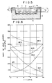
- FIG 4 is a chart showing the influences rendered to the quantities of radiated heat by the positions where the transparent heat trap 7A was provided between the transparent sheet and the absorber plate as shown in Figure 5.
- a heat trap 7A having a height I (10 mm) and being formed of collectively assembled square pillars each being hollow and having openings of HxH (5 mmx5 mm) was moved from a position contacting the transparent sheet 4 to a position contacting the absorber plate 2 within an interval L (25 mm) across the transparent sheet 4 and the absorber plate 2.
- the rates of heat losses were measured at respective positions where the heat trap 7A is provided.
- FIG 4 there are shown a convection heat loss BP1, a radiation heat loss BP2 and a sum in value of convection and radiation heat losses BP3 under the use of the black color coating treated absorber plate 2 and a convection heat loss SS1, a radiation heat loss SS2 and a sum of convection and .radiation heat losses SS3 under the use of the selective absorption surface treated absorber plate 2 respectively in correspondence to the position where the heat trap 7A are provided.
- the rate of heat losses in the solar heat collector reached the minimum value when the absorber plate 2 had been subjected at the surface thereof to the selective absorption surface treatment and the transparent heat trap 7A was disposed in contact with the transparent sheet 4.
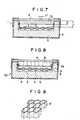
- FIG 6 is a chart showing the influences rendered to the rate of heat losses from the solar heat collector by the height of the transparent heat trap disposed in contact with the transparent sheet.
- a heat trap 7B formed of collectively assembled square pillars each being hollow and having openings of HxH (5 mmx5 mm) was disposed in contact with the transparent sheet 4 within the interval L (25 mm) across the absorber plate 2 and the transparent-sheet 4, the height I of the heat trap 7B is varied, and then, the rate of heat losses in accordance with the varied heights of the heat trap 7B were measured.
- FIG. 6 there are shown a convection heat loss BP1, a radiation heat loss BP2 and a sum of convection and radiation heat losses BP3 under the use of the black color coating treated absorber plate 2 and a convection heat loss SS1, a radiation heat loss SS2 and a sum of convection and radiation heat loss SS3 under the use of the selective absorption surface treated absorber plate 2 respectively in correspondence to the height of-the heat trap 7A.
- the structure of collectively assembled square pillars each being hollow and having the openings of HxH (5 mmx5 mm) was used as an example of the heat trap, however, it was ascertained that the substantially same results can be obtained even when the heat traps differing from in cross section from one having the form of the collectively assembled square pillars as described above are adopted. Additionally, in the present invention it is desirable that the wall thickness of the heat trap is thin and its emittance is low.
- FIG 8 is an explanatory view showing a solar heat collector 30 as an embodiment of the present invention.
- the solar heat collector 30 comprises: an absorber plate 2 for converting the solar rays into thermal energy and transmit it to a heat transfer medium; a heat transfer medium flow path 3 forming part of the absorber plate 2; a transparent sheet 4 made of glass or the like for preventing the convection heat loss from the absorber plate 2 and protecting the absorber plate 2 against the contamination and damages caused by the external factors; a heat insulating material 5 for preventing the heat loss through the rear surface of the solar heat collector; and an outer box 6 for totally housing the solar heat collector.
- the aforesaid absorber plate 2 is formed in such a manner that a multiplicity of tubes being flattened in cross section are connected to a flat plate at regular intervals or. two corrugated sheets are bonded to each other to form heat medium flow paths.
- the absorber plate 2 is subjected at the surface thereof to a selective absorption surface treatment.
- This absorber plate 2 is detachably mounted on opposing brackets 8 secured to the inner walls 6a of the aforesaid outer box 6 by suitable means.
- a honeycomb heat trap 31 formed of a transparent member formed of an ethylene fluoride resin film or the like as a heat trap is disposed between the absorber plate 2 and the transparent sheet 4.
- the honeycomb heat trap 31 is in contact at the upper end thereof with the aforesaid transparent sheet 4 and supported at the lower end thereof by thin lines 9 such as piano wires stretched across the opposing brackets 8.
- the height of the honeycomb heat trap 31 is determined to be about 1/2 of the interval across the absorber plate 2 and the transparent sheet 4.
- a fluoroplastics film as the material of the transparent heat trap, for example, a copolymer FEP (fluorinated ethylene-propylene) obtained from tetrafluoroethylene and hexafluoropropylene, a copolymer obtained from tetrafluorethylene and perfluoro- alkylvinylether (PFA) and a copolymer ETFE (ethylene-tetrafluoroethylene) obtained from fluoroethylene and ethylene.
- FEP fluorinated ethylene-propylene
- PFA perfluoro- alkylvinylether
- ETFE ethylene-tetrafluoroethylene
- the effect of convection heat loss prevention is high when spaces formed by the honeycomb heat trap 11 between the absorber plate 2 and the transparent sheet 4 are completely partitioned, while, as with the solar heat collector 40 shown in Figure 10, the effect of convection heat loss prevention is low when the honeycomb heat trap 41 is open at both the upper and lower ends.
- the effect of the convection heat loss prevention is medium when the honeycomb heat trap 31 is at the lower end only.
- the effect of radiation heat loss prevention becomes high by the selective absorption surface treatment applied to the surface of the absorbed plate 2.
- the honeycomb heat traps 11 and 21 as shown in Figures 2 and 3, respectively, are provided in contact with the absorber plates 2, the honeycomb heat traps 11 and 21 are heated to radiate large quantities of infrared rays, and in spite of the selective absorption surface treatment applied to the surfaces of the absorber plates 2, a high effect of radiation heat loss prevention cannot be achieved.
- the honeycomb heat trap 31 is disposed between the absorber plate 2 and the transparent sheet 4 in a manner to be spaced apart from the absorber plate 2 as far as possible, whereby the honeycomb heat trap 31 itself is suppressed in temperature rise, so that a satisfactory effect of radiation heat loss prevention can be achieved.
- the honeycomb heat trap 31 is not in contact with the absorber plate 2 and the temperature of the honeycomb heat trap 31 is low, whereby the thermal conductivity becomes low, thereby enabling to minimize the conduction heat loss.
- the maximum service temperature required becomes high
- the solar heat collector 30 shown in the abovedescribed embodiment of the present invention in which the honeycomb heat trap 31 is not in contact with the absorber plate 2 and spaced apart from the surface of the absorber plate 2 to a considerable extent, a temperature as low as 150° to 160°C suffices for a service temperature.
- the destructibility of the honeycomb heat trap is such that, when the honeycomb heat trap 11 is immovably confined between the absorber plate 2 and the transparent sheet 4 as in the solar heat collector 10 shown in Figure 2; the destruction occurs, that, whereas, when the honeycomb heat trap 31 is movable toward the absorber plate 2 as the transparent sheet 4 is deformed as in the solar heat collector 30 shown in the abovedescribed embodiment of the present invention, no destruction occurs.
- FIG 11 is a chart showing the collector efficience T1 vs AT/J, wherein AT is a temperature difference (°C) between the ambient temperature and the mean temperature of the heat transfer medium, J is an amount of solar radiation per unit of absorbing area (Kcal m- l h- 1 ), whereby the solar heat collector 30 shown in the abovedescribed embodiment of the present invention is compared in collector efficiency with the aforesaid solar heat collectors 1, 10, 20 and 40 of the prior art.
- Figure 11 shows that, in the normal heat collecting zone of the solar heat collector excluding the low heat collecting zone, the solar heat collector 30 shown in the abovedescribed embodiment of the present invention is outstanding in the collector efficiency.
- honeycomb heat trap 31 In the solar heat collector 30 shown in the abovedescribed embodiment of the present invention, description has been given of the case where the honeycomb heat trap 31 is applied as the trap, however, this honeycomb heat trap 31 may be replaced with the transparent heat trap 32 formed of collectively assembled square pillars as shown in Figure 12 or the heat trap 33 formed of collectively assembled cylinders as shown in Figure 13.
- honeycomb heat trap 31 of the solar heat collector 30 shown in the abovedescribed embodiment may be replaced with a continuous heat trap 34 being bent into continuous V-shapes in cross section at substantially a regular pitch and formed of a transparent member similar to the honeycomb heat trap 31 as shown in Figure 14 or a heat trap 35 formed of arranged cones as shown in Figure 15.
- the V-shaped heat trap 34 divides an intermediate air space layer between the absorber plate 2 and the transparent sheet 4 into two groups of spaces and the area thereof being in contact with the transparent sheet 4 becomes small, whereby the convection suppressing effect is enhanced, so that the conduction heat loss can be suppressed.
- the absorber plate in its box member which is provided at the surface thereof with the transparent sheet, the absorber plate is subjected at the surface thereof to the selective absorption surface treatment, there is the transparent heat trap having a height of about 1/2 of the interval across the transparent sheet and the absorber plate between the transparent sheet and the absorber plate in a manner to be in contact with the transparent sheet, so that such advantages can be achieved that the maximum service temperature for the heat trap material becomes low, the heat trap is not destructed by an external force and it is possible to suppress the heat losses in three forms due to the convection, radiation and conduction.
Description
- The invention relates to a solar heat collector with an outer box, with an absorber plate located in said outer box, with passages for heat collecting liquid, with a transparent sheet secured to an upper portion of said outer box and with a transparent heat trap located between said absorber plate and said transparent sheet and being held in contact with said transparent sheet over substantially the entire area of said absorber plate while making contact at its upper end with said transparent sheet.
- A solar heat collector of this type is known from DE-A-28 35 371. In this prior art document the transparent heat trap has the dual purpose of avoiding radiation and convection losses. To avoid radiation losses the heat trap is made of a material opaque to infrared radiations. By this measure, use is made of the so-called green-house effect. With same, a certain percentage of radiation losses may be avoided, however, a certain, relatively high percentage of heat loss through radiation is still present.
- Even in the US-A-4262657 and in the Stiebel Eltron catalogue "Planen mit Sonnenenergie", first Edition 1979, page 2-2, solar collectors are disclosed which make positive use of the green-house effect to suppress radiation losses.
- From FR-A-24 00 170, a solar heat collector is known which uses a heat trap between an absorber plate and a transparent sheet on the upper portion of the collector box. In this document, it is mentioned that the power element of the collector, which is a one piece element together with honeycomb heat trap structure could be made of fluoroethylene material.
- However, in this document, nothing is said about a selective absorption surface treatment of the absorber plate.
- It is the task of the present invention to provide a solar heat collector of the type above which is able to suppress heat losses in the three forms due to the convection, radiation and conduction more effectively as compared with prior art collectors.
- According to the invention this task is solved with the solar heat collector of the type above, which is characterised therein that said absorber plate has been subjected at the surface thereof to a selective absorption surface treatment and that the transparent heat trap is made of a fluoroethylene resin film, the height of said transparent heat trap being about one half of the distance between the transparent sheet and said absorber plate. With said solution, the invention avoids the generation of radiation losses by subjecting the surface of the absorber plate to a selective absorption surface treatment so that the heat trap may have only the function of a convection loss preventing structure.
- Further advantages of the invention are that the maximum surface temperature required for the heat trap is low and that the heat trap is set at a state where a possibility of breakdown is eliminated, and heat loss of the three forms due to convection radiation and conduction are effectively suppressed.
- Preferred embodiments of the invention are disclosed in the subclaims.
- The invention will now be described in conjunction with accompanying drawings wherein like reference numerals denote like elements. Some further prior art collectors are also depicted in the drawings.
- Figure 1 is a sectional view showing a conventional solar heat collector widely used;
- Figures 2 and 3 are sectional views showing the solar heat collectors of the prior art, respectively;
- Figure 4 is a chart showing the rate of heat losses from a solar heat collector;
- Figure 5 is a sectional view of the solar heat collector used for obtaining the characteristic curves shown in Figure 4;
- Figure 6 is a chart showing other rates of heat losses from a solar heat collector;
- Figure 7 is a sectional view showing the solar heat collector used for obtaining the characteristic curves shown in Figure 6;
- Figure 8 is a sectional view showing one embodiment of the solar heat collector according to the present invention;
- Figure 9 is a perspective view showing a convection heat loss preventive heat trap used in the solar heat collector according to the present invention as shown in Figure 8;
- Figure 10 is a sectional view showing the solar heat collector compared with one shown in Figure 8;
- Figure 11 is a chart showing the heat collecting efficiencies of the solar heat collectors; and
- Figures 12, 13, 14 and 15 are perspective views showing convection heat loss preventive heat traps applicable to the solar heat collector according to the present invention.
- Figure 1 is an explanatory view illustrating a solar heat collector 1 widely used. This solar heat collector 1 comprises: an
absorber plate 2 for converting the solar rays into thermal energy to transmit the thermal energy to a heat transfer medium such as water; a heat transfermedium flow path 3 formed in theabsorber plate 2; atransparent sheet 4 made of glass or the like for preventing the convection heat loss from theabsorber plate 2 and protecting the absorber plate.2 against the contamination and damages caused by the external factors; aheat insulating material 5 for preventing the heat loss through the rear surface of the solar heat collector; and anouter box 6 for protecting theabsorber plate 2 and theinsulating material 5, totally covering the solar heat collector in cooperation with thetransparent sheet 4. - The collector performance of the abovedescribed solar heat collector is improved by suppressing the convection radiation and conduction losses from the absorber. As the methods of suppressing the heat losses described above, heretofore, there have been adopted such methods that the surface of the
absorber plate 2 is subjected to a selective absorption surface treatment for suppressing the radiation heat loss, a convection preventive structure such as a honeycomb transparent heat trap for suppressing the convection heat loss is provided between theabsorber plate 2 and thetransparent sheet 4. - Figures 2 and 3 are explanatory views showing the conventional
solar heat collectors solar heat collector 10 shown in Figure 2, thehoneycomb heat trap 11 is provided between anabsorber plate 2 and atransparent sheet 4 in a manner to contact both theabsorber plate 2 and thetransparent sheet 4. Furthermore, in thesolar heat collector 20 shown in Figure 3, ahoneycomb heat trap 21 is provided between theabsorber plate 2 and thetransparent sheet 4 in a manner to contact theabsorber plate 2, but not to contact thetransparent sheet 4. - However, in the abovedescribed conventional
solar heat collectors honeycomb heat traps absorber plate 2, whereby the heat traps are heated to radiate large quantities of infrared rays, with the result that the radiation heat losses from thehoneycomb heat traps transparent sheets 4 increase to a high extent irrespective of that theabsorber plates 2 have been subjected to the selective absorption surface treatment for suppressing the radiation heat losses on the surfaces of theabsorber plates 2. Furthermore, in the conventionalsolar heat collector honeycomb heat traps solar heat collector 10, in the case of thehoneycomb heat trap 11 being located in close contact with theabsorber plate 2 and thetransparent sheet 4, it presents a disadvantage that thehoneycomb heat trap 11 may be broken down when thetransparent sheet 4 is deformed due to an external force such as wind pressure, snow load or the like. - Figure 4 is a chart showing the influences rendered to the quantities of radiated heat by the positions where the
transparent heat trap 7A was provided between the transparent sheet and the absorber plate as shown in Figure 5. In this experiment as shown in Figure 5, aheat trap 7A having a height I (10 mm) and being formed of collectively assembled square pillars each being hollow and having openings of HxH (5 mmx5 mm) was moved from a position contacting thetransparent sheet 4 to a position contacting theabsorber plate 2 within an interval L (25 mm) across thetransparent sheet 4 and theabsorber plate 2. During that movement, the rates of heat losses were measured at respective positions where theheat trap 7A is provided. Here, in Figure 5, the provision of theheat trap 7A is shown at a position where the center of theheat trap 7A is spaced apart a distance x from thetransparent sheet 4. Additionally, in this experiment, an absorber plate subjected at the surface thereof to a black color coating treatment of non selective absorption (BP) and another absorber plate subjected to at the surface thereof to a selective absorption surface treatment (SS) were used, and the above-described rates of heat losses were measured under the use of the respective absorber plates. - More specifically, in Figure 4, there are shown a convection heat loss BP1, a radiation heat loss BP2 and a sum in value of convection and radiation heat losses BP3 under the use of the black color coating treated
absorber plate 2 and a convection heat loss SS1, a radiation heat loss SS2 and a sum of convection and .radiation heat losses SS3 under the use of the selective absorption surface treatedabsorber plate 2 respectively in correspondence to the position where theheat trap 7A are provided. According to the results of this experiment, it was ascertained that the rate of heat losses in the solar heat collector reached the minimum value when theabsorber plate 2 had been subjected at the surface thereof to the selective absorption surface treatment and thetransparent heat trap 7A was disposed in contact with thetransparent sheet 4. - Figure 6 is a chart showing the influences rendered to the rate of heat losses from the solar heat collector by the height of the transparent heat trap disposed in contact with the transparent sheet. In this experiment, as shown in Figure 7, a heat trap 7B formed of collectively assembled square pillars each being hollow and having openings of HxH (5 mmx5 mm) was disposed in contact with the
transparent sheet 4 within the interval L (25 mm) across theabsorber plate 2 and the transparent-sheet 4, the height I of the heat trap 7B is varied, and then, the rate of heat losses in accordance with the varied heights of the heat trap 7B were measured. Furthermore, in this experiment, an absorber plate subjected at the surface thereof to a black color coating treatment of non-selective absorption and another absorber plate subjected at the surface thereof to a selective absorption surface treatment were used, and the abovedescribed rate of heat losses were measured under the use of the respective absorber plates. - More specifically, in Figure 6, there are shown a convection heat loss BP1, a radiation heat loss BP2 and a sum of convection and radiation heat losses BP3 under the use of the black color coating treated
absorber plate 2 and a convection heat loss SS1, a radiation heat loss SS2 and a sum of convection and radiation heat loss SS3 under the use of the selective absorption surface treatedabsorber plate 2 respectively in correspondence to the height of-theheat trap 7A. According to the results of the experiment shown in Figure 6, it was ascertained that the rate of heat losses from heat collector reached the minimum value when theabsorber plate 2 was subjected at the surface thereof to the selective absorption surface treatment and the height of the heat trap disposed in contact with the transparent sheet was set at a value substantially equal to 1/2xL. - In addition, in the respective embodiments described above, the structure of collectively assembled square pillars each being hollow and having the openings of HxH (5 mmx5 mm) was used as an example of the heat trap, however, it was ascertained that the substantially same results can be obtained even when the heat traps differing from in cross section from one having the form of the collectively assembled square pillars as described above are adopted. Additionally, in the present invention it is desirable that the wall thickness of the heat trap is thin and its emittance is low.
- Description will now be given of one embodiment of the present invention with reference to the accompanying drawings.
- Figure 8 is an explanatory view showing a
solar heat collector 30 as an embodiment of the present invention. Similarly to the solar heat collectors of the prior art, thesolar heat collector 30 comprises: anabsorber plate 2 for converting the solar rays into thermal energy and transmit it to a heat transfer medium; a heat transfermedium flow path 3 forming part of theabsorber plate 2; atransparent sheet 4 made of glass or the like for preventing the convection heat loss from theabsorber plate 2 and protecting theabsorber plate 2 against the contamination and damages caused by the external factors; aheat insulating material 5 for preventing the heat loss through the rear surface of the solar heat collector; and anouter box 6 for totally housing the solar heat collector. Theaforesaid absorber plate 2 is formed in such a manner that a multiplicity of tubes being flattened in cross section are connected to a flat plate at regular intervals or. two corrugated sheets are bonded to each other to form heat medium flow paths. Theabsorber plate 2 is subjected at the surface thereof to a selective absorption surface treatment. Thisabsorber plate 2 is detachably mounted on opposing brackets 8 secured to theinner walls 6a of the aforesaidouter box 6 by suitable means. - A
honeycomb heat trap 31 formed ofa transparent member formed of an ethylene fluoride resin film or the like as a heat trap is disposed between theabsorber plate 2 and thetransparent sheet 4. Thehoneycomb heat trap 31 is in contact at the upper end thereof with the aforesaidtransparent sheet 4 and supported at the lower end thereof by thin lines 9 such as piano wires stretched across the opposing brackets 8. The height of thehoneycomb heat trap 31 is determined to be about 1/2 of the interval across theabsorber plate 2 and thetransparent sheet 4. It is suitable to use a fluoroplastics film as the material of the transparent heat trap, for example, a copolymer FEP (fluorinated ethylene-propylene) obtained from tetrafluoroethylene and hexafluoropropylene, a copolymer obtained from tetrafluorethylene and perfluoro- alkylvinylether (PFA) and a copolymer ETFE (ethylene-tetrafluoroethylene) obtained from fluoroethylene and ethylene. - Description will hereunder be given of the heat collecting characteristics and the structural characteristics, referring to the following table, as compared with the heat collecting characteristics and the structural characteristics of the
solar heat collectors solar heat collector 40 wherein, as shown in Figure 10, thehoneycomb heat trap 41 is interposed between theabsorber plate 2 and thetransparent sheet 4 in a manner to contact neither theabsorber plate 2 nor thetransparent sheet 4. In addition, the effects of the respective characteristics are qualitatively indicated, and further, quantitatively indicated by use of the points of effects attached thereto.
- As with the
solar heat collector 10 shown in Figure 2, the effect of convection heat loss prevention is high when spaces formed by thehoneycomb heat trap 11 between theabsorber plate 2 and thetransparent sheet 4 are completely partitioned, while, as with thesolar heat collector 40 shown in Figure 10, the effect of convection heat loss prevention is low when thehoneycomb heat trap 41 is open at both the upper and lower ends. As with thesolar heat collector 30 shown in the embodiment of the present invention, the effect of the convection heat loss prevention is medium when thehoneycomb heat trap 31 is at the lower end only. - The effect of radiation heat loss prevention becomes high by the selective absorption surface treatment applied to the surface of the absorbed
plate 2. In thesolar heat collectors absorber plates 2, the honeycomb heat traps 11 and 21 are heated to radiate large quantities of infrared rays, and in spite of the selective absorption surface treatment applied to the surfaces of theabsorber plates 2, a high effect of radiation heat loss prevention cannot be achieved. In contrast thereto, in thesolar heat collector 30 shown in the above-described embodiment of the present invention, thehoneycomb heat trap 31 is disposed between theabsorber plate 2 and thetransparent sheet 4 in a manner to be spaced apart from theabsorber plate 2 as far as possible, whereby thehoneycomb heat trap 31 itself is suppressed in temperature rise, so that a satisfactory effect of radiation heat loss prevention can be achieved. - In the
solar heat collector 30 shown in the above-described embodiment of the present invention, wherein thehoneycomb heat trap 31 is not in contact with theabsorber plate 2 and the temperature of thehoneycomb heat trap 31 is low, whereby the thermal conductivity becomes low, thereby enabling to minimize the conduction heat loss. - As with the
solar heat collectors absorber plates 2, the maximum service temperature required becomes high, whereas, with thesolar heat collector 30 shown in the abovedescribed embodiment of the present invention, in which thehoneycomb heat trap 31 is not in contact with theabsorber plate 2 and spaced apart from the surface of theabsorber plate 2 to a considerable extent, a temperature as low as 150° to 160°C suffices for a service temperature. - The destructibility of the honeycomb heat trap is such that, when the
honeycomb heat trap 11 is immovably confined between theabsorber plate 2 and thetransparent sheet 4 as in thesolar heat collector 10 shown in Figure 2; the destruction occurs, that, whereas, when thehoneycomb heat trap 31 is movable toward theabsorber plate 2 as thetransparent sheet 4 is deformed as in thesolar heat collector 30 shown in the abovedescribed embodiment of the present invention, no destruction occurs. - Figure 11 is a chart showing the collector efficience T1 vs AT/J, wherein AT is a temperature difference (°C) between the ambient temperature and the mean temperature of the heat transfer medium, J is an amount of solar radiation per unit of absorbing area (Kcal m-lh-1), whereby the
solar heat collector 30 shown in the abovedescribed embodiment of the present invention is compared in collector efficiency with the aforesaidsolar heat collectors solar heat collector 30 shown in the abovedescribed embodiment of the present invention is outstanding in the collector efficiency. - In the
solar heat collector 30 shown in the abovedescribed embodiment of the present invention, description has been given of the case where thehoneycomb heat trap 31 is applied as the trap, however, thishoneycomb heat trap 31 may be replaced with thetransparent heat trap 32 formed of collectively assembled square pillars as shown in Figure 12 or theheat trap 33 formed of collectively assembled cylinders as shown in Figure 13. - Further, the
honeycomb heat trap 31 of thesolar heat collector 30 shown in the abovedescribed embodiment may be replaced with acontinuous heat trap 34 being bent into continuous V-shapes in cross section at substantially a regular pitch and formed of a transparent member similar to thehoneycomb heat trap 31 as shown in Figure 14 or aheat trap 35 formed of arranged cones as shown in Figure 15. The V-shapedheat trap 34 divides an intermediate air space layer between theabsorber plate 2 and thetransparent sheet 4 into two groups of spaces and the area thereof being in contact with thetransparent sheet 4 becomes small, whereby the convection suppressing effect is enhanced, so that the conduction heat loss can be suppressed. - As has been described hereinabove, according to the present invention, in the solar heat collector having the absorber plate in its box member which is provided at the surface thereof with the transparent sheet, the absorber plate is subjected at the surface thereof to the selective absorption surface treatment, there is the transparent heat trap having a height of about 1/2 of the interval across the transparent sheet and the absorber plate between the transparent sheet and the absorber plate in a manner to be in contact with the transparent sheet, so that such advantages can be achieved that the maximum service temperature for the heat trap material becomes low, the heat trap is not destructed by an external force and it is possible to suppress the heat losses in three forms due to the convection, radiation and conduction.
Claims (6)
Priority Applications (5)
| Application Number | Priority Date | Filing Date | Title |
|---|---|---|---|
| AU77708/81A AU547949B2 (en) | 1981-11-20 | 1981-11-20 | Solar heat collector |
| DE8181109807T DE3176235D1 (en) | 1981-11-20 | 1981-11-20 | Solar heat collector |
| DE198181109807T DE79976T1 (en) | 1981-11-20 | 1981-11-20 | SOLAR PANEL. |
| EP81109807A EP0079976B1 (en) | 1981-11-20 | 1981-11-20 | Solar heat collector |
| US06/622,403 US4791910A (en) | 1981-11-20 | 1984-06-21 | Solar heat collector |
Applications Claiming Priority (1)
| Application Number | Priority Date | Filing Date | Title |
|---|---|---|---|
| EP81109807A EP0079976B1 (en) | 1981-11-20 | 1981-11-20 | Solar heat collector |
Publications (2)
| Publication Number | Publication Date |
|---|---|
| EP0079976A1 EP0079976A1 (en) | 1983-06-01 |
| EP0079976B1 true EP0079976B1 (en) | 1987-06-03 |
Family
ID=8188025
Family Applications (1)
| Application Number | Title | Priority Date | Filing Date |
|---|---|---|---|
| EP81109807A Expired EP0079976B1 (en) | 1981-11-20 | 1981-11-20 | Solar heat collector |
Country Status (4)
| Country | Link |
|---|---|
| US (1) | US4791910A (en) |
| EP (1) | EP0079976B1 (en) |
| AU (1) | AU547949B2 (en) |
| DE (2) | DE3176235D1 (en) |
Families Citing this family (18)
| Publication number | Priority date | Publication date | Assignee | Title |
|---|---|---|---|---|
| DE3483386D1 (en) * | 1983-10-12 | 1990-11-15 | Shimon Klier | TRANSPARENT INSULATION DEVICE. |
| DE3445787A1 (en) * | 1984-12-11 | 1985-05-30 | Matthias 1000 Berlin Rosen | Heat exchanger surface |
| US4846151A (en) * | 1985-05-01 | 1989-07-11 | Simko Jr Frank A | Solar collectors |
| DE3824759A1 (en) * | 1988-07-21 | 1990-01-25 | Fraunhofer Ges Forschung | SOLAR COLLECTOR FOR GENERATING HIGH TEMPERATURES |
| WO1990004143A1 (en) * | 1988-10-03 | 1990-04-19 | Lasich John B | A system for heating fluid in process equipment with solar energy |
| DE3908363A1 (en) * | 1989-03-15 | 1990-09-27 | Fraunhofer Ges Forschung | SOLAR COLLECTOR |
| US5288537A (en) * | 1992-03-19 | 1994-02-22 | Hexcel Corporation | High thermal conductivity non-metallic honeycomb |
| US5466507A (en) * | 1993-10-14 | 1995-11-14 | Hexcel Corporation | High thermal conductivity non-metallic honeycomb with laminated cell walls |
| US5470633A (en) * | 1993-10-14 | 1995-11-28 | Hexcel Corporation | High thermal conductivity non-metallic honeycomb with optimum pitch fiber angle |
| US5527584A (en) * | 1993-10-19 | 1996-06-18 | Hexcel Corporation | High thermal conductivity triaxial non-metallic honeycomb |
| US5735262A (en) * | 1996-07-22 | 1998-04-07 | Stirling Thermal Motors, Inc. | Solar energy diffuser |
| AUPO987697A0 (en) * | 1997-10-17 | 1997-11-13 | Gough Industries Pty Ltd | Solar water heater |
| AU2002322832A1 (en) * | 2001-08-01 | 2003-02-17 | Eric C. Burckle | Photolytic cell for providing physiological gas exchange |
| ES2264350B1 (en) * | 2004-10-15 | 2007-11-01 | Gamesa Solar, S.A. Sociedad Unipersonal | METHOD FOR MANUFACTURE OF THERMAL SOLAR COLLECTORS. |
| US7434577B2 (en) * | 2006-02-28 | 2008-10-14 | Doherty Paul M | Solar air heater |
| WO2008081649A1 (en) * | 2006-12-28 | 2008-07-10 | Ngk Insulators, Ltd. | Process for producing plugged honeycomb structure |
| WO2012017387A1 (en) * | 2010-08-02 | 2012-02-09 | Tigi Ltd. | Transparent insulation panel retrofit for a solar collector |
| CN105202778B (en) * | 2014-06-12 | 2017-04-05 | 佛山圣哥拉太阳能科技有限公司 | A kind of plate solar collector |
Citations (2)
| Publication number | Priority date | Publication date | Assignee | Title |
|---|---|---|---|---|
| DE2835371A1 (en) * | 1977-08-12 | 1979-02-15 | Union Carbide Corp | SUN HEATER WITH HEAT TRAP |
| FR2400170A2 (en) * | 1977-08-12 | 1979-03-09 | Union Carbide Corp | Solar energy panel with honeycomb radiation trap - in which the cover plate and honeycomb form integral unit transparent to light but opaque to re-emitted infrared radiation |
Family Cites Families (7)
| Publication number | Priority date | Publication date | Assignee | Title |
|---|---|---|---|---|
| DE2336247A1 (en) * | 1973-07-17 | 1975-02-06 | Schoell Guenter | SOLAR PANEL |
| DE2543687A1 (en) * | 1974-10-09 | 1976-04-22 | Laing | SOLAR ENERGY COLLECTORS AND DEVICES OPERATING WITH THESE |
| US4019496A (en) * | 1975-04-07 | 1977-04-26 | Daystar Corporation | Collecting solar energy |
| US4114597A (en) * | 1975-12-31 | 1978-09-19 | The Franklin Institute | Unitary solar collector |
| US4078544A (en) * | 1976-04-26 | 1978-03-14 | The United States Of America As Represented By The United States Department Of Energy | Corrugated cover plate for flat plate collector |
| US4262657A (en) * | 1976-08-06 | 1981-04-21 | Union Carbide Corporation | Solar air heater |
| US4244354A (en) * | 1979-01-10 | 1981-01-13 | Williams Douglas J | Solar panel |
-
1981
- 1981-11-20 EP EP81109807A patent/EP0079976B1/en not_active Expired
- 1981-11-20 DE DE8181109807T patent/DE3176235D1/en not_active Expired
- 1981-11-20 AU AU77708/81A patent/AU547949B2/en not_active Expired
- 1981-11-20 DE DE198181109807T patent/DE79976T1/en active Pending
-
1984
- 1984-06-21 US US06/622,403 patent/US4791910A/en not_active Expired - Lifetime
Patent Citations (2)
| Publication number | Priority date | Publication date | Assignee | Title |
|---|---|---|---|---|
| DE2835371A1 (en) * | 1977-08-12 | 1979-02-15 | Union Carbide Corp | SUN HEATER WITH HEAT TRAP |
| FR2400170A2 (en) * | 1977-08-12 | 1979-03-09 | Union Carbide Corp | Solar energy panel with honeycomb radiation trap - in which the cover plate and honeycomb form integral unit transparent to light but opaque to re-emitted infrared radiation |
Non-Patent Citations (1)
| Title |
|---|
| Stiebel Eltron "Planen mit Sonnenenergie", 1st Edition 1979, 2-2 * |
Also Published As
| Publication number | Publication date |
|---|---|
| DE79976T1 (en) | 1983-09-29 |
| AU547949B2 (en) | 1985-11-14 |
| US4791910A (en) | 1988-12-20 |
| EP0079976A1 (en) | 1983-06-01 |
| AU7770881A (en) | 1983-05-26 |
| DE3176235D1 (en) | 1987-07-09 |
Similar Documents
| Publication | Publication Date | Title |
|---|---|---|
| EP0079976B1 (en) | Solar heat collector | |
| US3987784A (en) | Solar energy absorber panel | |
| US4080957A (en) | Solar panel | |
| US4201195A (en) | Jet impingement solar collector | |
| US4029080A (en) | Thermal collector of solar energy adapted for high temperature operation | |
| US4064868A (en) | Solar heat collector | |
| US4098261A (en) | Flat plate solar collector panel having extruded thermal conductors | |
| US4064866A (en) | Flat plate solar heat collector | |
| US4203421A (en) | Solar heat collector | |
| US4224927A (en) | Solar collector for heating a fluid | |
| KR101657754B1 (en) | Solar energy collecting module using vacuum panel | |
| US4290419A (en) | Multi systems solar collector | |
| JP2013508661A (en) | Solar collector | |
| US4716882A (en) | Solar heat collector | |
| US4509502A (en) | Multiple lens cover for solar heating panel | |
| US4150657A (en) | Solar collector | |
| GB1569804A (en) | Solar energy collector | |
| EP0076875B1 (en) | Solar energy collector | |
| US3995613A (en) | Solar heat collector unit | |
| US4316452A (en) | Solar collector | |
| US4149522A (en) | Solar heat collector with convection suppressor | |
| US3974823A (en) | Solar collector having minimum edge heat loss | |
| US4171694A (en) | Triangular duct solar panel | |
| GB2066447A (en) | Solar energy collector | |
| KR101899645B1 (en) | Solar energy vacuum heat collecting panel |
Legal Events
| Date | Code | Title | Description |
|---|---|---|---|
| PUAI | Public reference made under article 153(3) epc to a published international application that has entered the european phase |
Free format text: ORIGINAL CODE: 0009012 |
|
| AK | Designated contracting states |
Designated state(s): DE FR GB IT |
|
| ITCL | It: translation for ep claims filed |
Representative=s name: SOCIETA' ITALIANA BREVETTI S.P.A. |
|
| EL | Fr: translation of claims filed | ||
| DET | De: translation of patent claims | ||
| 17P | Request for examination filed |
Effective date: 19831021 |
|
| GRAA | (expected) grant |
Free format text: ORIGINAL CODE: 0009210 |
|
| AK | Designated contracting states |
Kind code of ref document: B1 Designated state(s): DE FR GB IT |
|
| ITF | It: translation for a ep patent filed |
Owner name: SOCIETA' ITALIANA BREVETTI S.P.A. |
|
| REF | Corresponds to: |
Ref document number: 3176235 Country of ref document: DE Date of ref document: 19870709 |
|
| ET | Fr: translation filed | ||
| PLBE | No opposition filed within time limit |
Free format text: ORIGINAL CODE: 0009261 |
|
| STAA | Information on the status of an ep patent application or granted ep patent |
Free format text: STATUS: NO OPPOSITION FILED WITHIN TIME LIMIT |
|
| 26N | No opposition filed | ||
| ITTA | It: last paid annual fee | ||
| PGFP | Annual fee paid to national office [announced via postgrant information from national office to epo] |
Ref country code: FR Payment date: 20001110 Year of fee payment: 20 |
|
| PGFP | Annual fee paid to national office [announced via postgrant information from national office to epo] |
Ref country code: DE Payment date: 20001113 Year of fee payment: 20 |
|
| PGFP | Annual fee paid to national office [announced via postgrant information from national office to epo] |
Ref country code: GB Payment date: 20001115 Year of fee payment: 20 |
|
| PG25 | Lapsed in a contracting state [announced via postgrant information from national office to epo] |
Ref country code: GB Free format text: LAPSE BECAUSE OF EXPIRATION OF PROTECTION Effective date: 20011119 |
|
| REG | Reference to a national code |
Ref country code: GB Ref legal event code: PE20 Effective date: 20011119 |