EP0079923B1 - Method and machine for packing a rope into a container - Google Patents
Method and machine for packing a rope into a container Download PDFInfo
- Publication number
- EP0079923B1 EP0079923B1 EP82901738A EP82901738A EP0079923B1 EP 0079923 B1 EP0079923 B1 EP 0079923B1 EP 82901738 A EP82901738 A EP 82901738A EP 82901738 A EP82901738 A EP 82901738A EP 0079923 B1 EP0079923 B1 EP 0079923B1
- Authority
- EP
- European Patent Office
- Prior art keywords
- rope
- container
- shaft
- winding head
- reel
- Prior art date
- Legal status (The legal status is an assumption and is not a legal conclusion. Google has not performed a legal analysis and makes no representation as to the accuracy of the status listed.)
- Expired
Links
Images

Classifications
-
- B—PERFORMING OPERATIONS; TRANSPORTING
- B65—CONVEYING; PACKING; STORING; HANDLING THIN OR FILAMENTARY MATERIAL
- B65H—HANDLING THIN OR FILAMENTARY MATERIAL, e.g. SHEETS, WEBS, CABLES
- B65H54/00—Winding, coiling, or depositing filamentary material
- B65H54/76—Depositing materials in cans or receptacles
- B65H54/80—Apparatus in which the depositing device or the receptacle is rotated
Definitions
- This invention relates to a method of packing a rope into a container in such a manner as to permit easy extraction of the rope therefrom, in which method the rope is withdrawn from a supply reel and led down into the container to be coiled therein with the coil centre situated between the centre line and periphery of the container, while the container is rotated and a simultaneous relative axial movement is effected between a winding head and the container and pressure is exerted on the rope placed in the container.
- US-A-3,234,627 and US-A-3,316,609 disclose machines for packing yarn into containers for subsequent dyeing. Such packing differs materially from rope packing. In the first place, the products are entirely different and cannot be handled in the same way. In the citations, the yarn is supplied by means of compressed air and simply is "dropped" down into the container in the form of loops which are shaped by means of a supply tube having a curved discharge end. This known type of machine cannot quite easily be used for packing a thick, long rope into a container.
- the object of the present invention is to pack such a rope in a novel manner so that all safety requirements are satisfied at the same time as the packing of the rope can be carried out mechanically.
- This object is attained by withdrawing the rope from the supply reel by introducing the rope between a fixed central piece in the winding head and a tubular pulling means rotating about said piece, such that the rope thus is caused to move at least part of a turn about the central piece before it exits as a coil from the lower end of the means and is discharged into the container, and rotating or twisting the rope about its longitudinal axis on its way down into the container.
- a new winding head for withdrawing the rope from a rope reel, coiling the rope and discharging it into a container, characterised by a tubular means in the lower end portion of a sleeve which is mounted on a vertical fixed shaft and rigidly connected to a rotatable rope reel supporting device for rotation therewith, said tubular means defining a cylindrical space, and an approximately cylindrical abutment mounted on the fixed shaft in the cylindrical space and defining together with the inner wall surface of the tubular means an annular gap in which the rope is receivable while being slightly pinched upon rotation of the means and from which gap the rope after having described at least part of a turn about the abutment is dischargeable as a coil at the lower open end.
- the invention also relates to a machine packing a rope of this kind, said machine comprising a frame with a shaft fixed at its upper end and extending a predetermined distance vertically downward, a supporting device rotatably mounted on the shaft and having a rope reel rotatably mounted thereon, a support means for the container for supporting it such that its centre line extends parallel to but laterally spaced from the fixed shaft, whereby said shaft projects into the container with its axis situated in the space between the centre line and periphery of the container, and means for compacting the rope placed in the container.
- Said machine is characterised by a rotary winding head on the free end of the fixed shaft projecting into the container, said winding head comprising a cylindrical sleeve which is mounted on the vertical fixed shaft and rigidly connected to the rope reel supporting device for rotation with it, a tubular means in the lower end portion of the sleeve facing away from the supporting means, said means defining a cylindrical space, and an approximately cylindrical abutment mounted on the fixed shaft in the cylindrical space and defining together with the inner wall surface of the tubular means an annular gap in which the rope is receivable while being slightly pinched upon rotation of the means and from which gap the rope after having described at least part of a turn about the abutment is dischargeable as a coil at the lower open end, the winding head being adapted, upon rotation, to withdraw the rope from the rope reel during the rotation of the reel supporting device and to coil the rope with the coil centre situated between the centre line and periphery of the container, and means for rotating the supporting device for the rope reel, the winding head and
- a machine has a frame 10 which is fixed to a bottom plate 11. At the top the frame has a transverse beam 12 in the centre of which a vertical shaft 13 is secured by means of a fastening device 14.
- the shaft 13 extends vertically downward and a supporting device generally designated 15 is rotatably mounted at a distance from the transverse beam 12.
- the supporting device 15 has a drive pulley 16 which is coaxial with the shaft 13 and about which a V-belt 17 is passed.
- the V-belt 17 is driven by a drive pulley 18.
- Secured to the supporting device 15 is a holder 19 for rotary accommodation of a rope supply reel 20 onto which is wound a rope 21.
- the supporting device 15 at the underside of the V-belt pulley 16 has a fastening 22 with which a tubular sleeve 23 is rigidly connected via flange means.
- the sleeve 23 extends about the shaft 13 coaxially therewith down to the lower end of the shaft 13.
- a tube 24 is connected to the underside of the supporting device 15 and the upper end of the tube opens opposite the longitudinal centre of the reel 20 mounted on the supporting device 15 while the lower end of the tube 24 opens adjacent the outer periphery of the sleeve 23.
- the rope 21 is intended to be pulled via a bushing in the supporting device 15 down through the tube to the point adjacent the periphery of the sleeve 23 and farther axially downward to a winding head 25 in the lower end of the shaft 13 and the sleeve 23.
- the winding head 25 consists of a cylindrical portion 26 which is fixed by means of a neck portion 52 and a stop screw 58 in the lower end of the sleeve 23.
- the cylindrical portion 26 extends downward past the lower end of the fixed shaft 13 projecting from the sleeve 23 and has below said lower end a cylindrical space.
- the portion 26 which defines the cylindrical space, and the neck portion 52 have a lining 27 of plastics, preferably Nylon@.
- the lining has a smooth inner side.
- a recess 28 extends from the outer side of the portion 26 and opens at the inner side of the lining 27.
- a cylindrical means 29 is fixed with the aid of a screw 55 to the lower end of the shaft 13.
- the means 29 has axial grooves 56, as shown in Fig. 3, and is received in the lined cylindrical space of the portion 26 with easy running fit to the wall of the space.
- the lining 27 has an enlarged cylindrical portion so that a gap 57 is formed between the lining and the periphery of the means 29, in which gap the rope 21 is receivable, while being slightly pinched between the lands of the means 29 and the lining 27.
- the rope running along the sleeve 23 is drawn in from the outer side of the sleeve to the gap 57 via the recess 28.
- Fig. 1 shows a container 31 into which the rope 21 is to be packed.
- the container 31 is cylindrical and has a likewise cylindrical tube 32 upstanding from the bottom, whereby an annular space is defined in the container 31.
- the radial extension of said annular space slightly exceeds the diameter of the winding head 25.
- the rope 21 is intended to be placed in said coils in said annular space by rotation of the winding head 25. To achieve this the container 31 must, however, be rotated about its axis, as will appear from Fig. 1, and at the same time be displaced vertically downwards.
- a support means 30 which on its upper side has support and holder means 33 for retaining the container 31.
- a threaded shaft 34 is connected to the underside of the support means and extends coaxially with the container 31.
- the shaft 34 is rotatable with the aid of a pulley 35 via a central fastening 36 therein.
- the pulley 35 is rotated by means of a V-belt 37 and a drive pulley 38 engaging said V-belt.
- the pulley 35 with the fastening 36 is mounted in a holder means 39 which is connected to the frame 10 and at its underside has a bushing 41 with a hollow crosspiece provided with a threaded portion 42 engaging the threads of the shaft 34, which by means of a handle 43 can be moved into and out of engagement with the threads of the shaft 34.
- a handle 43 can be moved into and out of engagement with the threads of the shaft 34.
- the engagement between the shaft 34 and the central fastening 36 of the pulley 35 is a frictional engagement which does not prevent the shaft 34 from moving axially.
- a disk 44 having a central opening of slightly greater diameter than that of the tube 32 and an opening for the winding head 25 is carried by arms 45,46 of which the latter is pivotally connected to the frame 10 and rockable by means of an eccentric 54.
- the purpose of the disk 44 will appear from the following.
- gearings 47,48 are provided, which are driven by means of a shaft 49 in turn driven by a V-belt pulley 51 via a worm gearing 50.
- gearings 47, 48 and 50 many other possibilities to drive the pulleys are conceivable.
- the described machine is used in the following manner to pack a rope 21 into the container 31.
- the rope 21 is drawn via the tube 24, the outer side of the sleeve 23 and the recess 28 to the gap 57 in the winding head 25.
- a sufficiently long rope length is withdrawn from the winding head 25to permit being placed along the inner surface of the container up to the upper edge and folded about said edge, such that the lowermost end of the rope is accessible.
- a container 31 is placed on the support means 30 and fixed in correct position.
- the shaft 34 can be urged axially upward until the winding head 25 is adjacent the bottom of the container 31.
- the threaded piece 42 is again engaged with the threads of the shaft 34 by swinging of the handle 43.
- the machine is now ready for start.
- the supporting device 15 When the machine is started the supporting device 15 is caused to rotate whereby the reel 20 is rotated about the shaft 13 as indicated at 20'. By this rotation the rope 21 drawn down to the winding head will be twisted or turn about its own axis, which generally is a prerequisite for its being discharged in a correct manner from the winding head.
- the portion 26 rotates because of its connection with the supporting device 15 via the sleeve 23 and the connecting means 22 atthe same speed of rotation as the reel 20 and the rope is discharged via the gap 57 in the portion 26 in coils from the winding head 25, as indicated to the left in Fig. 1.
- the container 31 is rotated very slowly via the support means 30 and the shaft 34 so that the coils are arranged in a uniform layer in the container 31 about the central tube 32 thereof.
- the container 31 has rotated a full revolution it has simultaneously moved a distance downwardly approximately corresponding to the rope thickness owing to the engagement of the threaded shaft 34 with the threaded piece 42, and a new layer of rope coils is placed on the layer already laid.
- the rope coils are placed below the disk 44 which has the task of pressing the laid layers together from above. If necessary, the disk 44 can be adapted to oscillate axially in that the eccentric 54 actuates the arm system 45, 46.
Abstract
Description
- This invention relates to a method of packing a rope into a container in such a manner as to permit easy extraction of the rope therefrom, in which method the rope is withdrawn from a supply reel and led down into the container to be coiled therein with the coil centre situated between the centre line and periphery of the container, while the container is rotated and a simultaneous relative axial movement is effected between a winding head and the container and pressure is exerted on the rope placed in the container.
- Survival equipments comprise a container with a rope which is intended for extraction by means of a rocket. For this reason it is of extreme importance that the rope runs out with the least possible resistance. This naturally places great demands on the packing of the rope, which at present is made entirely by hand and thus of course implies high packing costs. The reason why packing is carried out by hand simply is that hitherto no machine has been available, which is capable of performing this work with the desired reliability.
- US-A-3,234,627 and US-A-3,316,609 disclose machines for packing yarn into containers for subsequent dyeing. Such packing differs materially from rope packing. In the first place, the products are entirely different and cannot be handled in the same way. In the citations, the yarn is supplied by means of compressed air and simply is "dropped" down into the container in the form of loops which are shaped by means of a supply tube having a curved discharge end. This known type of machine cannot quite easily be used for packing a thick, long rope into a container.
- The object of the present invention is to pack such a rope in a novel manner so that all safety requirements are satisfied at the same time as the packing of the rope can be carried out mechanically. This object is attained by withdrawing the rope from the supply reel by introducing the rope between a fixed central piece in the winding head and a tubular pulling means rotating about said piece, such that the rope thus is caused to move at least part of a turn about the central piece before it exits as a coil from the lower end of the means and is discharged into the container, and rotating or twisting the rope about its longitudinal axis on its way down into the container.
- For packing the rope into a container, use is made of a new winding head for withdrawing the rope from a rope reel, coiling the rope and discharging it into a container, characterised by a tubular means in the lower end portion of a sleeve which is mounted on a vertical fixed shaft and rigidly connected to a rotatable rope reel supporting device for rotation therewith, said tubular means defining a cylindrical space, and an approximately cylindrical abutment mounted on the fixed shaft in the cylindrical space and defining together with the inner wall surface of the tubular means an annular gap in which the rope is receivable while being slightly pinched upon rotation of the means and from which gap the rope after having described at least part of a turn about the abutment is dischargeable as a coil at the lower open end.
- The invention also relates to a machine packing a rope of this kind, said machine comprising a frame with a shaft fixed at its upper end and extending a predetermined distance vertically downward, a supporting device rotatably mounted on the shaft and having a rope reel rotatably mounted thereon, a support means for the container for supporting it such that its centre line extends parallel to but laterally spaced from the fixed shaft, whereby said shaft projects into the container with its axis situated in the space between the centre line and periphery of the container, and means for compacting the rope placed in the container. Said machine is characterised by a rotary winding head on the free end of the fixed shaft projecting into the container, said winding head comprising a cylindrical sleeve which is mounted on the vertical fixed shaft and rigidly connected to the rope reel supporting device for rotation with it, a tubular means in the lower end portion of the sleeve facing away from the supporting means, said means defining a cylindrical space, and an approximately cylindrical abutment mounted on the fixed shaft in the cylindrical space and defining together with the inner wall surface of the tubular means an annular gap in which the rope is receivable while being slightly pinched upon rotation of the means and from which gap the rope after having described at least part of a turn about the abutment is dischargeable as a coil at the lower open end, the winding head being adapted, upon rotation, to withdraw the rope from the rope reel during the rotation of the reel supporting device and to coil the rope with the coil centre situated between the centre line and periphery of the container, and means for rotating the supporting device for the rope reel, the winding head and the support means with the container and simultaneously axially moving the support means vertically downward.
- The invention will be more fully described below with reference to the accompanying drawings in which:
- Fig. 1 in elevation shows an embodiment of the invention; and
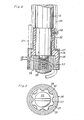
- Figs. 2 and 3 on a larger scale show a winding head in section and from below.
- According to Fig. 1 a machine according to the invention has a
frame 10 which is fixed to abottom plate 11. At the top the frame has atransverse beam 12 in the centre of which avertical shaft 13 is secured by means of afastening device 14. Theshaft 13 extends vertically downward and a supporting device generally designated 15 is rotatably mounted at a distance from thetransverse beam 12. The supportingdevice 15 has adrive pulley 16 which is coaxial with theshaft 13 and about which a V-belt 17 is passed. The V-belt 17 is driven by adrive pulley 18. Secured to the supportingdevice 15 is aholder 19 for rotary accommodation of arope supply reel 20 onto which is wound arope 21. The supportingdevice 15 at the underside of the V-belt pulley 16 has a fastening 22 with which atubular sleeve 23 is rigidly connected via flange means. Thesleeve 23 extends about theshaft 13 coaxially therewith down to the lower end of theshaft 13. Further, atube 24 is connected to the underside of the supportingdevice 15 and the upper end of the tube opens opposite the longitudinal centre of thereel 20 mounted on the supportingdevice 15 while the lower end of thetube 24 opens adjacent the outer periphery of thesleeve 23. Therope 21 is intended to be pulled via a bushing in the supportingdevice 15 down through the tube to the point adjacent the periphery of thesleeve 23 and farther axially downward to a windinghead 25 in the lower end of theshaft 13 and thesleeve 23. - As shown in Fig. 2, the
winding head 25 consists of acylindrical portion 26 which is fixed by means of aneck portion 52 and astop screw 58 in the lower end of thesleeve 23. Thecylindrical portion 26 extends downward past the lower end of thefixed shaft 13 projecting from thesleeve 23 and has below said lower end a cylindrical space. Theportion 26 which defines the cylindrical space, and theneck portion 52 have alining 27 of plastics, preferably Nylon@. The lining has a smooth inner side. Arecess 28 extends from the outer side of theportion 26 and opens at the inner side of thelining 27. Acylindrical means 29 is fixed with the aid of ascrew 55 to the lower end of theshaft 13. Themeans 29 hasaxial grooves 56, as shown in Fig. 3, and is received in the lined cylindrical space of theportion 26 with easy running fit to the wall of the space. At the lower end thelining 27 has an enlarged cylindrical portion so that agap 57 is formed between the lining and the periphery of themeans 29, in which gap therope 21 is receivable, while being slightly pinched between the lands of themeans 29 and thelining 27. The rope running along thesleeve 23 is drawn in from the outer side of the sleeve to thegap 57 via therecess 28. Part of the periphery of the rope within thegap 57 will touch themeans 29 at the lower end of theshaft 13 and upon rotation of thecylindrical portion 26 the rope will be drawn towards the downwardly facing outlet opening of thegap 57 and discharged from thewinding head 25 in the form of a coil having a diameter that normally slightly exceeds that of the winding head. - Fig. 1 shows a
container 31 into which therope 21 is to be packed. Thecontainer 31 is cylindrical and has a likewisecylindrical tube 32 upstanding from the bottom, whereby an annular space is defined in thecontainer 31. The radial extension of said annular space slightly exceeds the diameter of the windinghead 25. Therope 21 is intended to be placed in said coils in said annular space by rotation of thewinding head 25. To achieve this thecontainer 31 must, however, be rotated about its axis, as will appear from Fig. 1, and at the same time be displaced vertically downwards. - To have the
container 31 effect said movements a support means 30 is provided, which on its upper side has support and holder means 33 for retaining thecontainer 31. A threaded shaft 34 is connected to the underside of the support means and extends coaxially with thecontainer 31. The shaft 34 is rotatable with the aid of apulley 35 via acentral fastening 36 therein. Thepulley 35 is rotated by means of a V-belt 37 and adrive pulley 38 engaging said V-belt. Thepulley 35 with thefastening 36 is mounted in aholder means 39 which is connected to theframe 10 and at its underside has abushing 41 with a hollow crosspiece provided with a threadedportion 42 engaging the threads of the shaft 34, which by means of ahandle 43 can be moved into and out of engagement with the threads of the shaft 34. Upon rotation of the shaft 34 by means of thepulley 35 the shaft will also move axially because of its engagement with the threadedportion 42. The engagement between the shaft 34 and thecentral fastening 36 of thepulley 35 is a frictional engagement which does not prevent the shaft 34 from moving axially. - A
disk 44 having a central opening of slightly greater diameter than that of thetube 32 and an opening for thewinding head 25 is carried byarms frame 10 and rockable by means of an eccentric 54. The purpose of thedisk 44 will appear from the following. - For rotation of the
drive pulleys gearings shaft 49 in turn driven by a V-belt pulley 51 via a worm gearing 50. Instead of thegearings - The described machine is used in the following manner to pack a
rope 21 into thecontainer 31. First, therope 21 is drawn via thetube 24, the outer side of thesleeve 23 and the recess 28 to thegap 57 in thewinding head 25. Preferably, a sufficiently long rope length is withdrawn from the winding head 25to permit being placed along the inner surface of the container up to the upper edge and folded about said edge, such that the lowermost end of the rope is accessible. Then acontainer 31 is placed on the support means 30 and fixed in correct position. By detaching the threadedpiece 42 by means on thehandle 43 the shaft 34 can be urged axially upward until thewinding head 25 is adjacent the bottom of thecontainer 31. Then the threadedpiece 42 is again engaged with the threads of the shaft 34 by swinging of thehandle 43. The machine is now ready for start. - When the machine is started the supporting
device 15 is caused to rotate whereby thereel 20 is rotated about theshaft 13 as indicated at 20'. By this rotation therope 21 drawn down to the winding head will be twisted or turn about its own axis, which generally is a prerequisite for its being discharged in a correct manner from the winding head. Theportion 26 rotates because of its connection with the supportingdevice 15 via thesleeve 23 and the connecting means 22 atthe same speed of rotation as thereel 20 and the rope is discharged via thegap 57 in theportion 26 in coils from thewinding head 25, as indicated to the left in Fig. 1. At the same time thecontainer 31 is rotated very slowly via the support means 30 and the shaft 34 so that the coils are arranged in a uniform layer in thecontainer 31 about thecentral tube 32 thereof. When thecontainer 31 has rotated a full revolution it has simultaneously moved a distance downwardly approximately corresponding to the rope thickness owing to the engagement of the threaded shaft 34 with the threadedpiece 42, and a new layer of rope coils is placed on the layer already laid. The rope coils are placed below thedisk 44 which has the task of pressing the laid layers together from above. If necessary, thedisk 44 can be adapted to oscillate axially in that the eccentric 54 actuates thearm system container 31 the packing is interrupted and thecontainer 31 can be removed after further lowering, if any, of the support means 31 by release of the threadedpiece 42 and cutting therope 21. - With the aid of the machine according to the invention it is possible to pack a rope in the above-described manner in a fraction of the time required for manual packing of the rope. Besides, packing takes place in an extremely advantageous, safe manner and it has proved that the rope length which can be packed is considerably longer than that which can be packed in the same container by hand. The drawing shows a special container with a central tube, but it is obvious that applying the invention one can pack the rope also into other containers and for other purposes than that mentioned in the introduction.
Claims (8)
Priority Applications (1)
| Application Number | Priority Date | Filing Date | Title |
|---|---|---|---|
| AT82901738T ATE22873T1 (en) | 1981-05-29 | 1982-05-28 | METHOD AND DEVICE FOR PACKING A ROPE INTO A CONTAINER. |
Applications Claiming Priority (2)
| Application Number | Priority Date | Filing Date | Title |
|---|---|---|---|
| SE8103394 | 1981-05-29 | ||
| SE8103394A SE426227B (en) | 1981-05-29 | 1981-05-29 | SET AND MACHINE FOR PACKAGING A LINE IN A CONTAINER |
Publications (2)
| Publication Number | Publication Date |
|---|---|
| EP0079923A1 EP0079923A1 (en) | 1983-06-01 |
| EP0079923B1 true EP0079923B1 (en) | 1986-10-15 |
Family
ID=20343951
Family Applications (1)
| Application Number | Title | Priority Date | Filing Date |
|---|---|---|---|
| EP82901738A Expired EP0079923B1 (en) | 1981-05-29 | 1982-05-28 | Method and machine for packing a rope into a container |
Country Status (6)
| Country | Link |
|---|---|
| US (1) | US4590742A (en) |
| EP (1) | EP0079923B1 (en) |
| JP (1) | JPS58500804A (en) |
| DE (1) | DE3273775D1 (en) |
| SE (1) | SE426227B (en) |
| WO (1) | WO1982004239A1 (en) |
Families Citing this family (1)
| Publication number | Priority date | Publication date | Assignee | Title |
|---|---|---|---|---|
| GB2232951B (en) * | 1989-06-19 | 1993-02-24 | Process Improvements Ltd | Apparatus for producing layered tubes or rings |
Family Cites Families (9)
| Publication number | Priority date | Publication date | Assignee | Title |
|---|---|---|---|---|
| US444652A (en) * | 1891-01-13 | Apparatus for coiling metal rods | ||
| US911297A (en) * | 1907-11-08 | 1909-02-02 | Frances E Dawson | Machine for coiling and packing fiber. |
| US2981494A (en) * | 1958-04-22 | 1961-04-25 | Coulter & Mckenzie Machine Com | Variable speed wire coiling machine |
| US2936509A (en) * | 1958-10-07 | 1960-05-17 | Western Electric Co | Apparatus for collecting strands |
| US3234627A (en) * | 1962-07-31 | 1966-02-15 | Bancroft & Sons Co J | Dye package |
| US3316609A (en) * | 1964-04-16 | 1967-05-02 | Bancroft & Sons Co J | Apparatus for producing a yarn package |
| US3780963A (en) * | 1971-11-09 | 1973-12-25 | Krupp Gmbh | Wire-looping apparatus |
| DE2709252A1 (en) * | 1977-03-03 | 1978-09-07 | Neumuenster Masch App | DEVICE FOR DEPOSITING FIBER CABLES |
| US4080772A (en) * | 1977-05-06 | 1978-03-28 | Champion International Corporation | Apparatus for depositing materials in a container |
-
1981
- 1981-05-29 SE SE8103394A patent/SE426227B/en not_active IP Right Cessation
-
1982
- 1982-05-28 US US06/463,866 patent/US4590742A/en not_active Expired - Fee Related
- 1982-05-28 JP JP57501673A patent/JPS58500804A/en active Pending
- 1982-05-28 WO PCT/SE1982/000191 patent/WO1982004239A1/en active IP Right Grant
- 1982-05-28 EP EP82901738A patent/EP0079923B1/en not_active Expired
- 1982-05-28 DE DE8282901738T patent/DE3273775D1/en not_active Expired
Also Published As
| Publication number | Publication date |
|---|---|
| SE426227B (en) | 1982-12-20 |
| EP0079923A1 (en) | 1983-06-01 |
| WO1982004239A1 (en) | 1982-12-09 |
| JPS58500804A (en) | 1983-05-19 |
| DE3273775D1 (en) | 1986-11-20 |
| US4590742A (en) | 1986-05-27 |
| SE8103394L (en) | 1982-11-30 |
Similar Documents
| Publication | Publication Date | Title |
|---|---|---|
| US4340187A (en) | Bobbin changing apparatus | |
| US4995531A (en) | Ring dispenser | |
| US2998202A (en) | Initial thread end snagger | |
| US5526995A (en) | Yarn winding method | |
| US6045081A (en) | Method and apparatus for winding a continuously advancing yarn | |
| US5474208A (en) | Packaging material, apparatus and method | |
| US3977617A (en) | Film winding and perforating apparatus | |
| US3901456A (en) | Automatic winding machine | |
| US2620141A (en) | Winding machine for paper rolls | |
| US4169397A (en) | Device for processing a fibrous cable continuously fed at a high speed | |
| US3889891A (en) | Method and apparatus for transferring tape from a plurality of rolls | |
| NO144339B (en) | PROCEDURE AND DEVICE FOR DEVELOPING A CONTINUOUS TRADE | |
| EP0079923B1 (en) | Method and machine for packing a rope into a container | |
| US4147310A (en) | Apparatus for coiling wire | |
| US4377264A (en) | Spool handling device | |
| CN100415968C (en) | Method for removing residual yarn from spinning machine | |
| US4709452A (en) | Method and means of coiling start-up which prevents sliver slingover | |
| US3370798A (en) | Centerless winder | |
| US3542307A (en) | Receiving tray for strand material | |
| US4561602A (en) | Method and apparatus for facilitating doffing of a yarn processing machine | |
| US3745611A (en) | Apparatus for shirring artificial sausage casing | |
| US3796119A (en) | Staple fiber cutter | |
| US3247781A (en) | Automatic machine for tying or baling | |
| US3561694A (en) | Strand handling apparatus | |
| GB2087936A (en) | Yarn winding apparatus and method |
Legal Events
| Date | Code | Title | Description |
|---|---|---|---|
| PUAI | Public reference made under article 153(3) epc to a published international application that has entered the european phase |
Free format text: ORIGINAL CODE: 0009012 |
|
| 17P | Request for examination filed |
Effective date: 19830124 |
|
| AK | Designated contracting states |
Designated state(s): AT BE CH DE FR GB LI NL |
|
| GRAA | (expected) grant |
Free format text: ORIGINAL CODE: 0009210 |
|
| AK | Designated contracting states |
Kind code of ref document: B1 Designated state(s): AT BE CH DE FR GB LI NL |
|
| PG25 | Lapsed in a contracting state [announced via postgrant information from national office to epo] |
Ref country code: BE Effective date: 19861015 Ref country code: AT Effective date: 19861015 |
|
| REF | Corresponds to: |
Ref document number: 22873 Country of ref document: AT Date of ref document: 19861115 Kind code of ref document: T |
|
| ET | Fr: translation filed | ||
| REF | Corresponds to: |
Ref document number: 3273775 Country of ref document: DE Date of ref document: 19861120 |
|
| PGFP | Annual fee paid to national office [announced via postgrant information from national office to epo] |
Ref country code: NL Payment date: 19870531 Year of fee payment: 6 |
|
| PLBE | No opposition filed within time limit |
Free format text: ORIGINAL CODE: 0009261 |
|
| STAA | Information on the status of an ep patent application or granted ep patent |
Free format text: STATUS: NO OPPOSITION FILED WITHIN TIME LIMIT |
|
| 26N | No opposition filed | ||
| PG25 | Lapsed in a contracting state [announced via postgrant information from national office to epo] |
Ref country code: LI Effective date: 19890531 Ref country code: CH Effective date: 19890531 |
|
| PGFP | Annual fee paid to national office [announced via postgrant information from national office to epo] |
Ref country code: GB Payment date: 19890531 Year of fee payment: 8 |
|
| PG25 | Lapsed in a contracting state [announced via postgrant information from national office to epo] |
Ref country code: NL Effective date: 19891201 |
|
| NLV4 | Nl: lapsed or anulled due to non-payment of the annual fee | ||
| PG25 | Lapsed in a contracting state [announced via postgrant information from national office to epo] |
Ref country code: FR Free format text: LAPSE BECAUSE OF NON-PAYMENT OF DUE FEES Effective date: 19900131 |
|
| REG | Reference to a national code |
Ref country code: CH Ref legal event code: PL |
|
| PG25 | Lapsed in a contracting state [announced via postgrant information from national office to epo] |
Ref country code: DE Effective date: 19900201 |
|
| REG | Reference to a national code |
Ref country code: FR Ref legal event code: ST |
|
| PG25 | Lapsed in a contracting state [announced via postgrant information from national office to epo] |
Ref country code: GB Effective date: 19900528 |
|
| GBPC | Gb: european patent ceased through non-payment of renewal fee |