EP0079742A2 - Equalizing battery cell busbar - Google Patents
Equalizing battery cell busbar Download PDFInfo
- Publication number
- EP0079742A2 EP0079742A2 EP82305941A EP82305941A EP0079742A2 EP 0079742 A2 EP0079742 A2 EP 0079742A2 EP 82305941 A EP82305941 A EP 82305941A EP 82305941 A EP82305941 A EP 82305941A EP 0079742 A2 EP0079742 A2 EP 0079742A2
- Authority
- EP
- European Patent Office
- Prior art keywords
- busbar
- equalized
- terminal
- positive
- negative
- Prior art date
- Legal status (The legal status is an assumption and is not a legal conclusion. Google has not performed a legal analysis and makes no representation as to the accuracy of the status listed.)
- Granted
Links
Images
Classifications
-
- H—ELECTRICITY
- H01—ELECTRIC ELEMENTS
- H01M—PROCESSES OR MEANS, e.g. BATTERIES, FOR THE DIRECT CONVERSION OF CHEMICAL ENERGY INTO ELECTRICAL ENERGY
- H01M10/00—Secondary cells; Manufacture thereof
- H01M10/34—Gastight accumulators
- H01M10/345—Gastight metal hydride accumulators
-
- H—ELECTRICITY
- H01—ELECTRIC ELEMENTS
- H01M—PROCESSES OR MEANS, e.g. BATTERIES, FOR THE DIRECT CONVERSION OF CHEMICAL ENERGY INTO ELECTRICAL ENERGY
- H01M50/00—Constructional details or processes of manufacture of the non-active parts of electrochemical cells other than fuel cells, e.g. hybrid cells
- H01M50/50—Current conducting connections for cells or batteries
- H01M50/531—Electrode connections inside a battery casing
- H01M50/54—Connection of several leads or tabs of plate-like electrode stacks, e.g. electrode pole straps or bridges
-
- Y—GENERAL TAGGING OF NEW TECHNOLOGICAL DEVELOPMENTS; GENERAL TAGGING OF CROSS-SECTIONAL TECHNOLOGIES SPANNING OVER SEVERAL SECTIONS OF THE IPC; TECHNICAL SUBJECTS COVERED BY FORMER USPC CROSS-REFERENCE ART COLLECTIONS [XRACs] AND DIGESTS
- Y02—TECHNOLOGIES OR APPLICATIONS FOR MITIGATION OR ADAPTATION AGAINST CLIMATE CHANGE
- Y02E—REDUCTION OF GREENHOUSE GAS [GHG] EMISSIONS, RELATED TO ENERGY GENERATION, TRANSMISSION OR DISTRIBUTION
- Y02E60/00—Enabling technologies; Technologies with a potential or indirect contribution to GHG emissions mitigation
- Y02E60/10—Energy storage using batteries
-
- Y—GENERAL TAGGING OF NEW TECHNOLOGICAL DEVELOPMENTS; GENERAL TAGGING OF CROSS-SECTIONAL TECHNOLOGIES SPANNING OVER SEVERAL SECTIONS OF THE IPC; TECHNICAL SUBJECTS COVERED BY FORMER USPC CROSS-REFERENCE ART COLLECTIONS [XRACs] AND DIGESTS
- Y02—TECHNOLOGIES OR APPLICATIONS FOR MITIGATION OR ADAPTATION AGAINST CLIMATE CHANGE
- Y02P—CLIMATE CHANGE MITIGATION TECHNOLOGIES IN THE PRODUCTION OR PROCESSING OF GOODS
- Y02P70/00—Climate change mitigation technologies in the production process for final industrial or consumer products
- Y02P70/50—Manufacturing or production processes characterised by the final manufactured product
Definitions
- This invention pertains to the field of battery cells, and in particular, metal-gas batteries, such as nickel hydrogen batteries.
- U.S. patent 3,956,015 places both terminals on one side of the cell, although the terminals are perpendicular to the wall of the cell, unlike in the present invention.
- the '015 patent attempts to equalize the resistance within the cell for all module paths by means of utilizing individual leads from the terminals to each electrode.
- the path resistances are not exactly equal, however, because there are always minor variations in sizing and connecting the leads.
- the leads have to be insulated from each other, the resulting design is cumbersome, heavy, and unsuitable for spacecraft applications.
- U.S. patent 3,846,174 shows resistance balancing within a module, but not from module to module.
- both the negative and positive terminals enter the cell on the same end. This facilitates interconnections to the loads and keeps the conductor lengths short. This is very important in the case where weight and volume of a multicell battery must be minimized, such as in a spacecraft application.
- the second important feature is that the inner geometry of the battery cell of the present invention is such that the electrodes age equally. This is critical where one wishes to prolong the life of the battery cell while minimizing weight, as in a spacecraft. This goal is accomplished by means of equalizing the resistances along all paths internal to the cell corresponding to all electrode modules. Thus, each module contributes an equal amount of power to the overal capability of the battery and ages equally.
- the present invention achieves the above goals by utilizing a single equalizing busbar connected between either the positive or the negative terminal and one of the conventional busbars (the "equalized" busbar) at a region at the end of the electrode stack opposite from the end of the cell where the terminals are situated. This other terminal is connected to the end of the nonequalized busbar adjacent the end of the cell where the terminals are situated.
- the equalized busbar is the positive busbar in the case where the equalizing busbar is connected to the positive terminal; similarly, the 5 equalized busbar is the negative busbar in the case where the equalizing busbar is connected to the negative terminal.
- the equalizing busbar does not have to have the same resistance per unit length or the same length as either the positive or negative busbars, or as the conductor connecting the nonequalized terminal with the nonequalized busbars.
- the equalizing busbar should be kept as short as possible to minimize resistance losses and weight.
- the resistance increment between any two adjacent electrode connections along each of the positive and negative busbars should be substantially the same.
- a simple way to satisfy this condition is to provide the positive and the negative busbar (defined as extending only in the region of the electrode stack) with the same length and the same resistance per unit length.
- the internal resistance from positive to negative busbar within all electrode modules should be substantially the same.
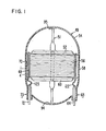
- Figure 1 illustrates a type of battery, a pressurized metal-gas battery cell 49, where the present invention has particular applicability.
- a reactant gas such as hydrogen permeates the interior of vessel 54.
- Electrode stack 56 comprising at least two electrode modules, contains the second reactant. Each module typically comprises one positive electrode 8, connected to positive busbar 68 (see Fig. 3), and one negative electrode 9, connected to negative busbar 58. Positive and negative electrodes are alternately stacked to form electrode stack 56. Separators, not shown, provide insulation between the electrodes and contain an electrolyte. Different separators may be present between modules, to permit access of reactant gas or provide electrical insulation.
- the negative electrodes 9 can be, for example, nickel catalyzed with platinum.
- the present invention can be advantageously utilized in any two-terminal battery cell having an electrode stack comprising at least two electrode modules, each module containing at least one positive and one negative electrode.
- the shape of cell 49 is shown as an elongated right circular cylindrical sleeve terminating on each end by a portion of an ellipsoid. In the example illustrated, each end is a half sphere. This is an optimum geometry for containing a high pressure gas.
- Penetrating the same end of cell 49 are positive terminal 73 and negative terminal 63.
- Electrode stack 56 is supported by an elongated, typically cylindrical center rod 51 of insulating material which exerts axially outward pressure against the inside surface of vessel 54 via washers 95 and 94.
- Insulating end plates 52 and 60 in this case circularly shaped, compress electrode stack 56 axially inwardly, and provide radial pressure outwardly against the interior of vessel 54.
- Weld ring 70 is used to facilitate welding two portions of vessel 54 together during fabrication of cell 49.
- Terminal 63 contains therewithin a conductive feedthrough 64 electrically insulated from vessel 54, which is normally a conductor, such as a thin steel.
- terminal 73 contains therewithin a conductive feedthrough 72 which is similarly electrically insulated from vessel 54.
- terminals 63 and 73 are substantially parallel to the longitudinal axis of the cell 49.
- a preferred means for constructing the dielectric seal between each of feedthroughs 64 and 72 and vessel 54 is described in our U.S. patent application serial number 297,374 filed August 28, 1981.
- F eedthrough 64 connects electrically with negative busbar 58 via flexible conductor 122.
- This terminal is illustrated as being the nonequalized terminal, although the negative terminal could just as readily be equalized, in which case terminal 73 would be the equalized terminal.
- terminal 73 is shown as the equalized terminal.
- Feedthrough 72 connects electrically with equalizing busbar 1 via flexible conductor 123.
- Equalizing busbar 1 is connected to positive busbar 68 at just one region, along stack 56 at that end remote from terminal 73.
- positive busbar 68 is the equalized busbar and negative busbar 58 is the nonequalized busbar in this illustration.
- Equalizing busbar 1 is always connected to the equalized busbar at only one region, i.e., at that end of the electrode stack 56 opposite from the end of battery cell 49 through which terminals 73 and 63 protrude.
- the important consideration is that the equalized busbar not touch the equalizing busbar in the region alongside stack 56, because the resistance increment between any two adjacent electrode connections along each of the positive and negative busbars must be the same.
- N is the resistance along the conductive path from the end of the nonequalized terminal (measured from the unconnected tip of feedthrough 72 or 64) to the nearest end of the nonequalized busbar.
- N is the resistance from the unconnected tip of feedthrough 64 through conductor 122 to the point of negative busbar 58 alongside the bottom of stack 56.
- M is the resistance through the path starting at that point of the equalized busbar alongside the top of stack 56 comprising equalizing busbar 1 plus the flexible conductor (123 or 122) plus the equalized feedthrough.
- M is the resistance from the top of busbar 68 through bar 1 to the unconnected tip of positive feedthrough 72.
- L is the-resistance of each of the nonequalized busbar and the equalized busbar in the region of stack 56.
- the following chart shows the internal path resistances for three different electrode modules within electrode stack 56:
- the internal resistance within cell 49 along the path traversing said module is equal to L+M+N+P, where P is the resistance through each module.
- M is independent of L and N and thus does not have to be any particular value. This means that the resistance of bar 1 does not need to have any particular value.
- the length of bar 1 is independent of the length of each of the equalized and non-equalized busbars.
- the resistance per unit length of bar 1 is independent of the resistance per unit length of each of the equalized and non-equalized busbars.
- M should be kept as small as possible to minimize loss and equalizing busbar 1 should be kept as lightweight as possible, especially for space applications.
- the resistance increments between any two adjacent electrodes along each of the equalized and nonequalized busbars must be the same. A simple way to satisfy this condition is to provide the equalized and nonequalized busbars with the same length and the same resistance per unit length. Also, the internal resistances P within each electrode module from the positive busbar to the negative busbar should be as equal as possible.
- busbars 1, 68, or 58 should touch wall 54, to avoid electrochemical reactions taking place on wall 54 which would adversely affect the power output of cell 49.
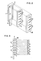
- equalizing busbar 1 has a lower portion 11 which connects to the flexible conductor (123 or 122) and an elongated rectangular portion 3 cut out by means of a rectangular hole to permit the passage therethrough of tabs 7 without electrical contact being made between tabs 7 and busbar 1.
- Each tab 7 is the termination of an electrode of the same polarity as the equalized busbar; here, positive electrodes 8 and positive busbar 68. The function of each tab 7 is to provide a means for making electrical contact between each electrode 8 and busbar 68.
- Busbar 68 is shown having the shape of an elongated rectangular bar having narrow rectangular slits disposed transverse to its long dimension. Slits 6 are dimensioned so as to accept tabs 7. Weld tabs may be preinserted in slits 6 to facilitate the welding of tabs 7 to busbar 68.
- Equalizing busbar 1 has an upper ridge 2 which is welded, soldered, or otherwise conductively bonded to the top of busbar 68. This is the only region at which busbars 1 and 68 make contact.
- Insulator 4 shown having an elongated rectangular shape, is disposed between busbars 1 and 68 to insure that 1 and 68 will not touch in the region of stack 56. Insulator 4 can be cut through with a series of thin rectangular slits 5 disposed transverse to its long axis for accepting and providing mechanical support for tabs 7.
Landscapes
- Chemical & Material Sciences (AREA)
- Chemical Kinetics & Catalysis (AREA)
- Electrochemistry (AREA)
- General Chemical & Material Sciences (AREA)
- Engineering & Computer Science (AREA)
- Manufacturing & Machinery (AREA)
- Connection Of Batteries Or Terminals (AREA)
- Hybrid Cells (AREA)
Abstract
Description
- This invention pertains to the field of battery cells, and in particular, metal-gas batteries, such as nickel hydrogen batteries.
- A prior art search uncovered the following U.S. patent references:
- U.S. patent 4,115,630 accomplishes one of the goals of the present invention, i.e., the equal aging of electrode modules by means of equalization of resistance among internal paths traversing all modules; however, this patent does not suggest how this goal can be accomplished with the further goal of locating both terminals at the same end of the cell. In fact, integral to the design of the '630 patent is the placement of each terminal along the cell's cylindrical axis, thereby precluding placement of both terminals at the same end.
- U.S. patent 3,956,015 places both terminals on one side of the cell, although the terminals are perpendicular to the wall of the cell, unlike in the present invention. The '015 patent attempts to equalize the resistance within the cell for all module paths by means of utilizing individual leads from the terminals to each electrode. The path resistances are not exactly equal, however, because there are always minor variations in sizing and connecting the leads. Furthermore, since the leads have to be insulated from each other, the resulting design is cumbersome, heavy, and unsuitable for spacecraft applications.
- U.S. patents 3,899,351; 4,004,067; 4,004,068; 4,098,962; 4,127,703; 4,128,703; and 4,159,367 show battery cells with positive and negative terminals situated on the same end of the cell. However, none of the patents teaches the use of resistance balancing among module paths so as to prolong the life of the battery as in the present invention.
- U.S. patent 3,846,174 shows resistance balancing within a module, but not from module to module.
- In the battery cell of the present invention, two important goals are realized. First, both the negative and positive terminals enter the cell on the same end. This facilitates interconnections to the loads and keeps the conductor lengths short. This is very important in the case where weight and volume of a multicell battery must be minimized, such as in a spacecraft application.
- The second important feature is that the inner geometry of the battery cell of the present invention is such that the electrodes age equally. This is critical where one wishes to prolong the life of the battery cell while minimizing weight, as in a spacecraft. This goal is accomplished by means of equalizing the resistances along all paths internal to the cell corresponding to all electrode modules. Thus, each module contributes an equal amount of power to the overal capability of the battery and ages equally.
- The difficulty of accomplishing both goals simultaneously is exemplified by the large number of patents cited above describing battery cells which are unable to do so.
- The present invention achieves the above goals by utilizing a single equalizing busbar connected between either the positive or the negative terminal and one of the conventional busbars (the "equalized" busbar) at a region at the end of the electrode stack opposite from the end of the cell where the terminals are situated. This other terminal is connected to the end of the nonequalized busbar adjacent the end of the cell where the terminals are situated. The equalized busbar is the positive busbar in the case where the equalizing busbar is connected to the positive terminal; similarly, the 5 equalized busbar is the negative busbar in the case where the equalizing busbar is connected to the negative terminal.
- Surprisingly, the equalizing busbar does not have to have the same resistance per unit length or the same length as either the positive or negative busbars, or as the conductor connecting the nonequalized terminal with the nonequalized busbars. As a general rule, the equalizing busbar should be kept as short as possible to minimize resistance losses and weight.
- The resistance increment between any two adjacent electrode connections along each of the positive and negative busbars should be substantially the same. A simple way to satisfy this condition is to provide the positive and the negative busbar (defined as extending only in the region of the electrode stack) with the same length and the same resistance per unit length. The internal resistance from positive to negative busbar within all electrode modules should be substantially the same.
- The invention will now be described with reference to the accompanying drawings, in which:
- Figure 1 is a partly schematic, partly cross- sectional side view of a battery cell utilizing the present invention;
- Figure 2 is an exploded perspective view of one embodiment of the equalizing busbar of the present invention; and
- Figure 3 is a side view of the embodiment illustrated in Figure 2.
- Figure 1 illustrates a type of battery, a pressurized metal-
gas battery cell 49, where the present invention has particular applicability. A reactant gas such as hydrogen permeates the interior ofvessel 54.Electrode stack 56, comprising at least two electrode modules, contains the second reactant. Each module typically comprises onepositive electrode 8, connected to positive busbar 68 (see Fig. 3), and onenegative electrode 9, connected tonegative busbar 58. Positive and negative electrodes are alternately stacked to formelectrode stack 56. Separators, not shown, provide insulation between the electrodes and contain an electrolyte. Different separators may be present between modules, to permit access of reactant gas or provide electrical insulation. In the case where hydrogen is the first reactant, thenegative electrodes 9 can be, for example, nickel catalyzed with platinum. - While the description herein is oriented around pressurized metal/gas cells as one example, the present invention can be advantageously utilized in any two-terminal battery cell having an electrode stack comprising at least two electrode modules, each module containing at least one positive and one negative electrode.
- The shape of
cell 49 is shown as an elongated right circular cylindrical sleeve terminating on each end by a portion of an ellipsoid. In the example illustrated, each end is a half sphere. This is an optimum geometry for containing a high pressure gas. - Penetrating the same end of
cell 49 are positive terminal 73 andnegative terminal 63. -
Electrode stack 56 is supported by an elongated, typicallycylindrical center rod 51 of insulating material which exerts axially outward pressure against the inside surface ofvessel 54 viawashers end plates electrode stack 56 axially inwardly, and provide radial pressure outwardly against the interior ofvessel 54.Weld ring 70 is used to facilitate welding two portions ofvessel 54 together during fabrication ofcell 49. - Such a battery is described in more detail in a U.S. patent application by Meyer and Hickman entitled "Lightweight Metal-Gas Battery", commonly assigned with the present invention and mailed to the U.S. Patent and Trademark Office on November 2, 1981.
-
Terminal 63 contains therewithin aconductive feedthrough 64 electrically insulated fromvessel 54, which is normally a conductor, such as a thin steel. Similarly, terminal 73 contains therewithin aconductive feedthrough 72 which is similarly electrically insulated fromvessel 54. Preferably,terminals 63 and 73 are substantially parallel to the longitudinal axis of thecell 49. A preferred means for constructing the dielectric seal between each offeedthroughs vessel 54 is described in our U.S. patent application serial number 297,374 filed August 28, 1981. - Feedthrough 64 connects electrically with
negative busbar 58 viaflexible conductor 122. This terminal is illustrated as being the nonequalized terminal, although the negative terminal could just as readily be equalized, in which case terminal 73 would be the equalized terminal. Here, terminal 73 is shown as the equalized terminal. Feedthrough 72 connects electrically with equalizing busbar 1 viaflexible conductor 123. Equalizing busbar 1 is connected topositive busbar 68 at just one region, alongstack 56 at that end remote from terminal 73. Thus,positive busbar 68 is the equalized busbar andnegative busbar 58 is the nonequalized busbar in this illustration. - Equalizing busbar 1 is always connected to the equalized busbar at only one region, i.e., at that end of the electrode stack 56 opposite from the end of
battery cell 49 through whichterminals 73 and 63 protrude. The important consideration is that the equalized busbar not touch the equalizing busbar in the region alongsidestack 56, because the resistance increment between any two adjacent electrode connections along each of the positive and negative busbars must be the same. - The operation of the present invention and the means by which the resistances through all electrode module paths are equalized can be understood by examining the following table. N is the resistance along the conductive path from the end of the nonequalized terminal (measured from the unconnected tip of
feedthrough 72 or 64) to the nearest end of the nonequalized busbar. Thus, in the embodiment illustrated, N is the resistance from the unconnected tip offeedthrough 64 throughconductor 122 to the point ofnegative busbar 58 alongside the bottom ofstack 56. - M is the resistance through the path starting at that point of the equalized busbar alongside the top of
stack 56 comprising equalizing busbar 1 plus the flexible conductor (123 or 122) plus the equalized feedthrough. Thus, here M is the resistance from the top ofbusbar 68 through bar 1 to the unconnected tip ofpositive feedthrough 72. - L is the-resistance of each of the nonequalized busbar and the equalized busbar in the region of
stack 56. The following chart shows the internal path resistances for three different electrode modules within electrode stack 56:
- It can be seen from the above table that regardless of the location of the electrode module, the internal resistance within
cell 49 along the path traversing said module is equal to L+M+N+P, where P is the resistance through each module. It can also be noted from the above that M is independent of L and N and thus does not have to be any particular value. This means that the resistance of bar 1 does not need to have any particular value. The length of bar 1 is independent of the length of each of the equalized and non-equalized busbars. The resistance per unit length of bar 1 is independent of the resistance per unit length of each of the equalized and non-equalized busbars. As a general rule, M should be kept as small as possible to minimize loss and equalizing busbar 1 should be kept as lightweight as possible, especially for space applications. - The resistance increments between any two adjacent electrodes along each of the equalized and nonequalized busbars must be the same. A simple way to satisfy this condition is to provide the equalized and nonequalized busbars with the same length and the same resistance per unit length. Also, the internal resistances P within each electrode module from the positive busbar to the negative busbar should be as equal as possible.
- None of
busbars wall 54, to avoid electrochemical reactions taking place onwall 54 which would adversely affect the power output ofcell 49. - Since the above are the only limitations on the invention it can be readily appreciated that there are many possible ways of effectuating equalizing busbar 1. For example, it could be implemented in the form of a conductor passing through the center of insulating
center rod 51 on its way to the equalized terminal. The embodiment illustrated is just one example of a working embodiment, and is seen in detail in Figures 2 and 3. We see that equalizing busbar 1 has alower portion 11 which connects to the flexible conductor (123 or 122) and an elongated rectangular portion 3 cut out by means of a rectangular hole to permit the passage therethrough of tabs 7 without electrical contact being made between tabs 7 and busbar 1. Each tab 7 is the termination of an electrode of the same polarity as the equalized busbar; here,positive electrodes 8 andpositive busbar 68. The function of each tab 7 is to provide a means for making electrical contact between eachelectrode 8 andbusbar 68. -
Busbar 68 is shown having the shape of an elongated rectangular bar having narrow rectangular slits disposed transverse to its long dimension.Slits 6 are dimensioned so as to accept tabs 7. Weld tabs may be preinserted inslits 6 to facilitate the welding of tabs 7 tobusbar 68. - Equalizing busbar 1 has an
upper ridge 2 which is welded, soldered, or otherwise conductively bonded to the top ofbusbar 68. This is the only region at whichbusbars 1 and 68 make contact. Insulator 4, shown having an elongated rectangular shape, is disposed betweenbusbars 1 and 68 to insure that 1 and 68 will not touch in the region ofstack 56. Insulator 4 can be cut through with a series of thin rectangular slits 5 disposed transverse to its long axis for accepting and providing mechanical support for tabs 7.
Claims (7)
Applications Claiming Priority (2)
| Application Number | Priority Date | Filing Date | Title |
|---|---|---|---|
| US06/321,514 US4411970A (en) | 1981-11-16 | 1981-11-16 | Equalizing battery cell busbar |
| US321514 | 1989-03-09 |
Publications (3)
| Publication Number | Publication Date |
|---|---|
| EP0079742A2 true EP0079742A2 (en) | 1983-05-25 |
| EP0079742A3 EP0079742A3 (en) | 1985-04-17 |
| EP0079742B1 EP0079742B1 (en) | 1988-12-21 |
Family
ID=23250918
Family Applications (1)
| Application Number | Title | Priority Date | Filing Date |
|---|---|---|---|
| EP82305941A Expired EP0079742B1 (en) | 1981-11-16 | 1982-11-08 | Equalizing battery cell busbar |
Country Status (5)
| Country | Link |
|---|---|
| US (1) | US4411970A (en) |
| EP (1) | EP0079742B1 (en) |
| JP (2) | JPS5889784A (en) |
| CA (1) | CA1180754A (en) |
| DE (1) | DE3279299D1 (en) |
Families Citing this family (10)
| Publication number | Priority date | Publication date | Assignee | Title |
|---|---|---|---|---|
| US4950564A (en) * | 1988-05-02 | 1990-08-21 | Gates Energy Products, Inc. | Metal gas cell |
| US5002842A (en) * | 1988-05-02 | 1991-03-26 | Gates Energy Products, Inc. | End plate for a metal gas cell |
| US5227267A (en) * | 1990-11-01 | 1993-07-13 | Yardney Technical Products, Inc. | Disc electrode and busbar for an electrochemical battery |
| JP4626101B2 (en) * | 2001-07-04 | 2011-02-02 | 株式会社デンソー | DC-DC converter |
| DE102008050437B4 (en) * | 2008-10-08 | 2015-02-19 | Auto-Kabel Management Gmbh | Scalable automotive battery and method of manufacturing the same |
| JP5658450B2 (en) * | 2009-11-12 | 2015-01-28 | 川崎重工業株式会社 | Battery system |
| WO2016062250A1 (en) | 2014-10-23 | 2016-04-28 | Quantum Force Engineering Limited | Battery assembly |
| ES2797130T3 (en) * | 2015-12-30 | 2020-12-01 | Ampd Energy Ltd | Battery assembly with resistive compensation paths between battery terminals |
| US20230282890A1 (en) * | 2022-03-04 | 2023-09-07 | EnerVenue, Inc | Electrode Stack Assembly for a Metal Hydrogen Battery |
| JP7609822B2 (en) * | 2022-05-10 | 2025-01-07 | 矢崎総業株式会社 | Busbars |
Family Cites Families (13)
| Publication number | Priority date | Publication date | Assignee | Title |
|---|---|---|---|---|
| US1587951A (en) * | 1923-02-14 | 1926-06-08 | Harrison Newton | Storage battery |
| US3990910A (en) * | 1972-05-31 | 1976-11-09 | Tyco Laboratories, Inc. | Nickel-hydrogen battery |
| US3846174A (en) * | 1973-04-11 | 1974-11-05 | E Barrett | Proportioned current battery |
| US3899351A (en) * | 1974-06-12 | 1975-08-12 | Bell Telephone Labor Inc | Formation of electrodes for alkaline batteries |
| US3956015A (en) * | 1975-06-06 | 1976-05-11 | The United States Of America As Represented By The Secretary Of The Air Force | Lightweight nickel hydrogen cell |
| US4038461A (en) * | 1976-01-28 | 1977-07-26 | The United States Of America As Represented By The Secretary Of The Air Force | Electrochemical cell having balanced distribution of oxygen and electrolyte |
| US4127703A (en) * | 1976-02-05 | 1978-11-28 | Eic Corporation | Nickel-hydrogen secondary battery |
| US4004067A (en) * | 1976-06-07 | 1977-01-18 | Aeronutronic Ford Corporation | Rechargeable electrochemical cell |
| US4004068A (en) * | 1976-06-07 | 1977-01-18 | Aeronutronic Ford Corporation | Electrochemical cell of a rechargeable nature |
| US4115630A (en) * | 1977-03-17 | 1978-09-19 | Communications Satellite Corporation | Metal-hydrogen battery |
| US4098962A (en) * | 1977-04-14 | 1978-07-04 | Yardney Electric Corporation | Metal-hydrogen secondary battery system |
| US4128703A (en) * | 1977-07-05 | 1978-12-05 | Wilson Greatbatch Ltd. | Lithium-iodine cell |
| US4159367A (en) * | 1978-06-29 | 1979-06-26 | Yardney Electric Corporation | Hydrogen electrochemical cell and rechargeable metal-hydrogen battery |
-
1981
- 1981-11-16 US US06/321,514 patent/US4411970A/en not_active Expired - Lifetime
-
1982
- 1982-11-01 CA CA000414595A patent/CA1180754A/en not_active Expired
- 1982-11-08 DE DE8282305941T patent/DE3279299D1/en not_active Expired
- 1982-11-08 EP EP82305941A patent/EP0079742B1/en not_active Expired
- 1982-11-12 JP JP57197855A patent/JPS5889784A/en active Pending
-
1991
- 1991-10-01 JP JP1991087597U patent/JPH0524130Y2/ja not_active Expired - Lifetime
Also Published As
| Publication number | Publication date |
|---|---|
| JPH0524130Y2 (en) | 1993-06-18 |
| EP0079742A3 (en) | 1985-04-17 |
| CA1180754A (en) | 1985-01-08 |
| JPH0499361U (en) | 1992-08-27 |
| EP0079742B1 (en) | 1988-12-21 |
| JPS5889784A (en) | 1983-05-28 |
| DE3279299D1 (en) | 1989-01-26 |
| US4411970A (en) | 1983-10-25 |
Similar Documents
| Publication | Publication Date | Title |
|---|---|---|
| EP0290764B1 (en) | Cylindrical bipolar electrode battery | |
| US4567119A (en) | Nickel-hydrogen bipolar battery | |
| US7867651B2 (en) | Low impedance layered battery apparatus and method for making the same | |
| EP0123010A1 (en) | Primary battery | |
| US4038462A (en) | Solid-electrolyte battery, particularly for the storage of electrical energy | |
| US4262064A (en) | Toroidal cell and battery | |
| US4411970A (en) | Equalizing battery cell busbar | |
| US20030190520A1 (en) | Wound bipolar lithium polymer batteries | |
| EP1059683B1 (en) | Bussing structure in an electrochemical cell | |
| US3607403A (en) | Self-charging battery incorporating a solid-gas battery and storage battery within a honeycomb matrix | |
| EP0061724B1 (en) | Cell employing a coiled electrode assembly | |
| US12401085B2 (en) | Cell module having a plurality of electrochemical pouch cells | |
| US6045943A (en) | Electrode assembly for high energy density batteries | |
| EP0192388A2 (en) | Support assembly for cells of a secondary battery | |
| EP0144771A2 (en) | Electrochemical cell having a plurality of battery stacks | |
| US4276361A (en) | Electrochemical cell with electrode hold-down | |
| US3956015A (en) | Lightweight nickel hydrogen cell | |
| US4471035A (en) | Electrochemical battery | |
| US4410608A (en) | Electrochemical cell | |
| JP2020198228A (en) | Battery pack | |
| US3922175A (en) | Plural cell battery | |
| US4113923A (en) | Fuel cell including at least one improved element | |
| CN224053344U (en) | A cylindrical battery pack and battery device | |
| US4668592A (en) | Electrochemical cell having porous metal coupling members | |
| CN115882126B (en) | Battery case, cylindrical battery and battery module |
Legal Events
| Date | Code | Title | Description |
|---|---|---|---|
| PUAI | Public reference made under article 153(3) epc to a published international application that has entered the european phase |
Free format text: ORIGINAL CODE: 0009012 |
|
| AK | Designated contracting states |
Designated state(s): DE FR GB |
|
| PUAL | Search report despatched |
Free format text: ORIGINAL CODE: 0009013 |
|
| AK | Designated contracting states |
Designated state(s): DE FR GB |
|
| 17P | Request for examination filed |
Effective date: 19850906 |
|
| 17Q | First examination report despatched |
Effective date: 19860310 |
|
| R17C | First examination report despatched (corrected) |
Effective date: 19860729 |
|
| GRAA | (expected) grant |
Free format text: ORIGINAL CODE: 0009210 |
|
| AK | Designated contracting states |
Kind code of ref document: B1 Designated state(s): DE FR GB |
|
| REF | Corresponds to: |
Ref document number: 3279299 Country of ref document: DE Date of ref document: 19890126 |
|
| ET | Fr: translation filed | ||
| R20 | Corrections of a patent specification |
Effective date: 19890629 |
|
| PLBE | No opposition filed within time limit |
Free format text: ORIGINAL CODE: 0009261 |
|
| STAA | Information on the status of an ep patent application or granted ep patent |
Free format text: STATUS: NO OPPOSITION FILED WITHIN TIME LIMIT |
|
| 26N | No opposition filed | ||
| REG | Reference to a national code |
Ref country code: GB Ref legal event code: 732E |
|
| REG | Reference to a national code |
Ref country code: FR Ref legal event code: TP |
|
| PGFP | Annual fee paid to national office [announced via postgrant information from national office to epo] |
Ref country code: GB Payment date: 20011018 Year of fee payment: 20 Ref country code: FR Payment date: 20011018 Year of fee payment: 20 Ref country code: DE Payment date: 20011018 Year of fee payment: 20 |
|
| REG | Reference to a national code |
Ref country code: GB Ref legal event code: IF02 |
|
| PG25 | Lapsed in a contracting state [announced via postgrant information from national office to epo] |
Ref country code: GB Free format text: LAPSE BECAUSE OF EXPIRATION OF PROTECTION Effective date: 20021107 |
|
| REG | Reference to a national code |
Ref country code: GB Ref legal event code: PE20 Effective date: 20021107 |